Note: Descriptions are shown in the official language in which they were submitted.
CA 02655328 2012-05-24
ROTOR HUB OF A WIND ENERGY PLANT
Description
The invention relates to a rotor hub of a wind power plant for a ro-
tor, in particular with at least one rotor blade, wherein a hub core
body and at least one hub outer body are connected together. Fur-
thermore, the invention relates to a wind power plant with a rotor
hub.
In wind power plants, a rotor blade is fastened in a pivotable man-
ner on a rotor hub with a blade bearing. Known wind power plants
consist of a tower, a nacelle arranged on the upper end of the
tower, a rotor that is pivot-mounted around a rotor axis on the out-
side of the nacelle and that has a rotor hub and at least one rotor
blade extending from the rotor hub. A generic wind power plant is
for example described in DE-A-10 2004 023 773, which has a rotor
hub with a blade adjustment system.
EP-B-1 303 698 also discloses a rotor hub of a wind power plant.
The rotor hub establishes a mechanical connection between the ro-
CA 02655328 2008-12-15
-2-
for shaft or the rotor axis and the rotor blades.
Starting from this state of the art, the object of the present invention
is to provide a rotor hub that can be produced and installed easily
and cost-effectively, wherein it should be possible to transport lar-
ger rotor hubs in an efficient manner.
This object is solved through a rotor hub of a wind power plant for a
rotor, in particular with at least one rotor blade, wherein a hub core
body and at least one hub outer body are connected together by
means of a flange connection, which is further established in that
the flange connection is constructed with a predetermined tilt angle
towards the rotational axis of the rotor, wherein the tilt angle of the
flange connection is constructed larger than the tilt angle of the ro-
tor blade connection surface of the hub outer body.
In particular, a multi-part rotor hub is provided, which is formed in
the fully installed state, e.g. on a nacelle of a wind power plant, from
a separate hub core body and at least one or more separate hub
outer bodies. It is possible within the framework of the invention that
a rotor blade is already provided or designed with a hub outer body.
The invention is based on the idea that in the case of a hingeless
rotor or a rigid rotor hub of a wind power plant, in which a rigid con-
nection of the rotor blades with the rotor axis or shaft occurs via the
hingeless or rigid rotor hub, a flange connection is provided, which
is arranged in a connection plane and assumes a predetermined
angle with the rotational axis of the rotor or the rotor shaft. In the
geometric sense, the rotor axis breaks through the plane in which
the planar connection surface of the connection flange or the flange
connection between the hub core body and the hub outer body lies.
For this, the flange connection between the hub core body, which
CA 02655328 2008-12-15
-3-
will be or is connected with the rotor shaft, and the hub outer body
between the hub core body and the rotor blade arranged on it, is
preferably designed as a planar connection surface.
Compared to the previous connections of the connection body be-
tween the outer rotor blade and the hub core body, the plane, in
which the flange connection between the core body and the connec-
tion body is arranged, is designed tilted. In the case of the previous
connections, the connection planes of the flange and the rotor axis
are aligned parallel to each other so that they cannot touch or cut
each other. Moreover, in other known connections according to the
state of the art, the connection planes for rotor blades are tilted to-
wards the rotational axis with a tilt angle in the range of Y. Accord-
ing to the invention, this tilt angle of the connection plane of the ro-
tor blades is smaller than the tilt angle of the connection surface
between the hub core body and the hub outer body or bodies.
In accordance with the invention, a rotor hub of a wind power plant
is provided, which has a hub core body as the rotor hub body,
wherein the hub core body will be or is connected with a rotor shaft.
The hub core body also has at least one flange connection, the sur-
face of which is tilted towards the rotational axis of the rotor shaft in
a predetermined angle. It should also be noted that, according to
the invention, the surface of the flange connection is arranged at a
predetermined, non-right angle to the rotor blade axis of a rotor
blade.
The hub core body connects the rotor hub as the central piece with
the rotor shaft. The connection bodies or hub outer bodies are ar-
ranged on the flange connection arranged tilted towards the rotation
axis of the rotor so that the rotor blades can be or are mounted on
it.
CA 02655328 2008-12-15
-4-
Due to the diagonally tilted or designed flange connections running
towards the rotor axis, it is possible to design a separable, i.e. multi-
part, rotor hub so that the transport of individual parts of the rotor
hub, e.g. the hub core body and/or hub outer body, is thereby facili-
tated. The individual transported parts of the rotor hub are then put
together at the installation location of a wind power plant and are
connected together for example with the help of screw connections
via the flange connections. In accordance with the invention, it is
thus possible to transport for example rotor hubs with flange con-
nections that are 3 m to 6 m in diameter after production to the in-
stallation location without problems.
In accordance with an alternative solution of the object or in another
embodiment, it is provided that the height of the hub core body is
smaller than the diameter of the, in particular circular or round, rotor
blade connection surface of the hub outer body, wherein in particu-
lar the flange connection between the hub core body and the hub
outer body is advantageously designed in a circular or round man-
ner. It is thereby possible to provide a multi-part rotor hub, which
due to the lower height of the hub core body compared to the, pref-
erably circular, blade flange diameter of the hub outer body permits
a simple transport of the hub core body, since the height of the hub
core body can be considered the transport height of the hub core
body. For example, a hub core body with a connection diameter of
the ring flange on the rotor shaft side of 3 m and a height of less
than 4 m can thus be transported on a transport vehicle, wherein a
rotor blade with a (round) blade flange diameter of more than 4 m
can be attached to the fully installed rotor hub with hub core body
and at least one hub outer body. For example, the height of the hub
core body between 0.5 m to 2.5 m is smaller than the blade flange
diameter.
CA 02655328 2008-12-15
-5-
In a preferred embodiment, the flange connection between the hub
core body and the hub outer body is designed in a circular, i.e.
round, manner. This also has the advantage that, due to the round
connection point in the area of the flange connection, a more fixed
connection is established between the hub body and the connection
body attached to it during installation, since more screws are dis-
tributed around the circular flange circumference compared to an
oval flange circumference. There are also numerous advantages
during production.
In order to provide a rotor that has several rotor blades, it is also
provided that several flange connections are designed on the rotor
hub between the hub core body and several hub rotor blade connec-
tion bodies.
It is also advantageously provided that the flange connections are
arranged or provided regularly on the hub core body.
In particular, the or each hub outer body is connected with a rotor
blade. In the case of a wind power plan with a rotor, which has sev-
eral rotor blades, the connection bodies are each connected with a
rotor blade.
It is also beneficial if the hub outer body and the hub core bodies
are permanently connected with each other.
In order to make it possible for maintenance personnel to access
the rotor, an access opening is also provided on the hub core body.
Within the framework of the invention, another access opening can
also be provided on another point of the rotor or nacelle.
CA 02655328 2008-12-15
_g_
In particular, the access opening is designed in the area of the rotor
axis on the hub core body. It is also conceivable that the access
opening is provided on another point of the rotor hub.
For the fastening of rotor blades on the rotor hub, the hub outer
body on the rotor blade side has a flange connection so that a rotor
blade is fastened or arranged on it. The flange connection is also
called a rotor blade flange or blade flange.
The rotor-blade-side flange connection is preferably designed in a
circular manner in order to establish a reliable connection between
the rotor blade and the respective connection body and to enable
simple pitch control of the rotor blade by means of a round blade
bearing.
Furthermore, according to a preferred embodiment of the rotor hub
according to the invention, it is suggested that the diameter of the
rotor-blade-side flange connection of the hub outer body is larger
than the diameter of the, in particular circular, hub-core-body-side
flange connection. This results in optimized conditions with respect
to the stiffness, the weight and the dimensions of a hub core body
or a rotor hub according to the invention. Easy transport is hereby
possible for large rotor hubs, to which rotor blades e.g. with a blade
flange diameter greater than 4 m are attached, since the transport
height or height of the hub core body is smaller than the blade
flange diameter.
The object is also solved through a wind power plant, which is pro-
vided with a separated or separable rotor hub according to the in-
vention with connection surfaces tilted towards the rotational axis.
In order to avoid repetitions reference to the above explanations is
made expressly.
CA 02655328 2008-12-15
-7-
The invention is described below, without restricting the general in-
tent of the invention, based on an exemplary embodiment, wherein
reference to the drawings is made with regard to the disclosure of
all details according to the invention that are not explained in
greater detail in the text.
Fig. 1 shows a cross-section through a rotor hub according to
the invention and
Fig. 2 shows a view from the top of the rotor hub according to
the invention in accordance with Fig. 1.
In the following figures, the same or similar types of elements or
corresponding parts are provided with the same reference numbers
in order to prevent the item from needing to be reintroduced.
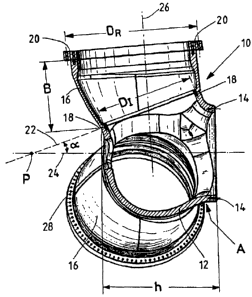
Fig. 1 shows a cross-section of a rotor hub 10. The rotor hub 10 has
a hub core body 12, which is connected with the rotor shaft of the
wind power plant (not shown) via a ring flange 14. Based on the
cross-sectional representation, Fig. 1 shows the connection of the
hub core body 12 with a hub outer body 16. The ring flange 14 typi-
cally has a diameter of e.g. 3 m for a wind power plant with a power
of 8 to 12 megawatts.
Fig. 1 also shows the height h of the hub core body 12, which is for
example less than 4 m. The height h is an important variable for the
transport of the hub core body 12 since the transport height of a
transport vehicle is determined by it. A simple transport over nor-
mal streets is possible without problem at a height of less than 4 m.
As can be seen in Fig. 2, the view from the top of the rotor hub 10 is
CA 02655328 2008-12-15
-8-
designed such that three hub outer bodies 16 are arranged in a
star-like manner and evenly on the hub core body 12. On the hub
outer body 16, the rotor blades (not shown) are connected in a pivo-
table manner with the hub outer body 16 via corresponding flanges
and blade bearings 20.
Furthermore, it can be seen from Fig. 2 that three outer parts in the
form of the hub outer bodies 16 are arranged on the hub core body
12. The rotor hub 10 thus consists of a number of separate bodies
or individual components, which are connected with each other dur-
ing the erection of a wind power plant.
In order to connect the hub outer body 16 with the hub core body
12, a flange 18 is provided between the two bodies so that the two
bodies 12 and 16 can be assembled and connected together in a
fixed manner. It can be seen in Fig. 1 that the flange connection 18
lies in a plane 22 that is located at a predetermined angle with re-
spect to the rotational axis 24 of the rotor. Plane 22 and rotational
axis 24 thereby assume an angle a, which is designed as an acute
angle. In the geometric sense, the rotational axis 24 breaks through
the plane 22 at point P.
According to the invention, all connection flanges or flange connec-
tions 18 on the hub core body 12 for the hub outer body 16 are ar-
ranged at a predetermined angle with respect to the rotational axis
24 of the rotor.
Due to the fact that the plane 22 is not arranged parallel to the rota-
tional axis 24, it is possible to build the hub core body 12 in a
space-saving manner for transport and larger hub core bodies 12 of
a rotor hub 10 up to a size of 6 m without creating greater difficulties
during transport. It will be possible to produce the hub body 12 in a
CA 02655328 2008-12-15
-9-
compact manner due to the inclination of plane 22, in which the
flange connection 18 is arranged. Individual pieces are preferably
produced in a casting process.
Moreover, Fig. 1 shows a rotor blade axis 26 of a rotor blade (not
shown here), which also lies at a predetermined angle with the ex-
clusion of a right angle and an angle area between 85 to 900 with
respect to the rotor axis 24.
Furthermore, the flange connection 18 on the hub core body 12 is
designed in a circular manner for production reasons, whereby a
fixed and stable connection is established between the hub core
body 12 and the hub outer body 16.
The hub core body 12 also has an access opening 28 on the outside
of the hub core body 12, i.e. on the side facing away from the na-
celle of a wind power plant, which is dimensioned such that mainte-
nance personnel can climb into the hub core body 12 designed as a
hollow part in order to perform maintenance work. Naturally, it is
possible within the framework of the invention to provide an access
opening for the maintenance personnel at another point on the rotor
hub. For example, the access opening can be designed in an area A
of the hub core body 12 marked laterally, which lies close to the
connection with the rotor shaft or close to the ring flange 14, or on
or in one of the hub outer bodies 16.
The angle a is preferably between plane 22 and rotational axis 24
on the order of magnitude between 10 and 75 . In a preferred em-
bodiment, angle a is ideally greater than 15 , in particular between
15 and 45 . It is hereby possible to achieve a particularly compact
design of the hub core body 12 as an individual component in the
shape of a cone or tapering body.
CA 02655328 2008-12-15
-10-
Fig. 1 also shows the pitch circle diameters of the flange connec-
tions 18 and the flange connection 20 (blade flange connection).
This shows that the diameter DR of the flange connection 20 is
greater than the diameter D, of the flange connection 18 between
the hub core body 12 and the hub outer body 16. Moreover, the
flange connection 20 is preferably arranged in a plane that is mainly
parallel to the rotational axis 24 of the rotor hub 10. For example,
the diameter DR has a size of more than 4 m, in particular more than
4.5 m. The diameter DR of the flange connection is thus greater than
the height h of the hub core body 12 with a value of e.g. less than 4
m. Moreover, Fig. 1 shows the front-side construction height B of
the hub outer body 16, which is preferably not larger or smaller than
the height h of the hub core body 12 and lies e.g. in a range of 2 m
to3m.
Fig. 2 also shows that the flange connections 18 between the hub
core body 12 and the three hub outer bodies 16 are designed evenly
on the hub core body. The bore holes of the screw connections on
the flange connections 18 are hereby evenly distributed around the
circumference so that more screw connections are thereby provided
on the flange 18 between the two bodies 12 and 16 than e.g. in the
case of oval flanges that are parallel to the rotor axis 24.
In particular the large rotor blade bending moments in the direction
of the wind (flapping moments) can thus be particularly safely ab-
sorbed.
CA 02655328 2008-12-15
-11-
List of References
Rotor hub
12 Hub core body
5 14 Ring flange
16 Hub outer body
18 Flange connection
Flange connection
22 Plane
10 24 Rotational axis
26 Rotor blade axis
28 Access opening
a Angle
A Area
15 B Construction height
DR Diameter
D, Diameter
h Height
P Intersection point