Language selection

Search

Patent 2655704 Summary

Third-party information liability

Some of the information on this Web page has been provided by external sources. The Government of Canada is not responsible for the accuracy, reliability or currency of the information supplied by external sources. Users wishing to rely upon this information should consult directly with the source of the information. Content provided by external sources is not subject to official languages, privacy and accessibility requirements.

Claims and Abstract availability

Any discrepancies in the text and image of the Claims and Abstract are due to differing posting times. Text of the Claims and Abstract are posted:

  • At the time the application is open to public inspection;
  • At the time of issue of the patent (grant).
(12) Patent: (11) CA 2655704
(54) English Title: LIQUID CONTAINER LID WITH DISPENSING AND SEALING MECHANISM
(54) French Title: COUVERCLE DE CONTENANT A LIQUIDE AVEC MECANISME DE DISTRIBUTION ET D'OBTURATION
Status: Granted
Bibliographic Data
(51) International Patent Classification (IPC):
  • B65D 47/14 (2006.01)
  • B65D 51/16 (2006.01)
(72) Inventors :
  • LAIB, DOUGLAS M. (United States of America)
  • VAN VAERENBERGH, TOM (Belgium)
(73) Owners :
  • DART INDUSTRIES INC. (United States of America)
(71) Applicants :
  • DART INDUSTRIES INC. (United States of America)
(74) Agent: GOWLING WLG (CANADA) LLP
(74) Associate agent:
(45) Issued: 2017-01-03
(22) Filed Date: 2009-02-26
(41) Open to Public Inspection: 2009-09-21
Examination requested: 2013-11-19
Availability of licence: N/A
(25) Language of filing: English

Patent Cooperation Treaty (PCT): No

(30) Application Priority Data:
Application No. Country/Territory Date
12/076,756 United States of America 2008-03-21

Abstracts

English Abstract

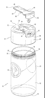
A liquid container lid for use on a container is disclosed having a pouring spout disposed on an upper surface of the lid, a vent hole disposed on the upper surface of the lid and rear of the pouring spout, a pair of U-shaped lugs disposed on the upper surface of the lid and rear of the vent hole, a seal plate having a trunnion on a lower surface thereof, and a post extending downwardly from the lower surface and opposing the trunnion, a gasket removably disposed over the post on the seal plate, the trunnion of the seal plate pivotally engaging the pair of U-shaped lugs, allowing the seal plate to pivot in a cantilevered motion from a first raised position to a second lowered position wherein the gasket is inserted in the pouring spout and seals the pouring spout.


French Abstract

Un couvercle de contenant à liquide pour utilisation sur un contenant est décrit, lequel comporte un bec verseur placé sur une surface supérieure du couvercle, un évent placé sur la surface supérieure du couvercle et larrière du bec verseur, une paire de pattes à logement en U placées sur la surface supérieure du couvercle et à larrière de lévent, une plaque détanchéité avec un tourillon sur une surface inférieure de celui-ci, et un montant sétendant vers le bas à partir de la surface inférieure et opposé au tourillon, un joint détanchéité placé de façon amovible sur le montant de la plaque détanchéité, le tourillon de la plaque détanchéité mettant en prise de manière pivotante la paire de pattes à logement en U, permettant à la plaque détanchéité de pivoter dans un mouvement en porte-à-faux à partir dune première position soulevée à une seconde position abaissée dans laquelle le joint détanchéité est inséré dans le bec verseur et obture le bec verseur.

Claims

Note: Claims are shown in the official language in which they were submitted.


What is claimed is:
1. A liquid container lid for use on a container having an outer wall and
an
upper peripheral rim bounding an opening, said liquid container lid
comprising:
a pouring spout disposed on an upper surface of the lid,
a vent means disposed on the upper surface of the lid,
a seal plate having an upper surface and a lower surface,
seal plate attaching means for pivotally attaching the seal plate to said
upper surface of the lid, the plate attaching means having a first member
disposed on the upper surface of the lid and a second member disposed on the
lower surface of the seal plate,
a gasket removably disposed on the lower surface of said seal plate, and
a vent closing means disposed on the lower surface of said seal plate,
wherein the second member of the seal plate attaching means is located
between two opposing ends of the seal plate so that said seal plate is
pivotable in
a cantilevered motion between a lowered closed position and a raised open
position,
wherein the gasket is inserted in and seals the pouring spout when the
seal plate is in the lowered closed position,
wherein the seal plate attaching means has locking means for releasably
locking the seal plate in the lowered closed position, the locking means
comprising a protrusion and a cam respectively formed on one of the first
member and the second member of the seal plate attaching means,
wherein a cut out portion diametrically spans an upper portion of the lid
and has a sloped rear surface portion and a flat surface portion forward of
the
sloped rear surface portion,
wherein the pouring spout and the vent means are disposed on the flat
surface portion, and

11

wherein the seal plate attaching means is provided between the sloped
rear surface portion and the flat surface portion.
2. The liquid container lid of claim 1, wherein said vent means comprises a

vent hole.
3. The liquid container lid of claim 2, wherein said vent hole is located
rear of
said pouring spout, and said vent closing means blocks said vent hole when
said
seal plate is in said lowered closed position.
4. The liquid container lid of any one of claims 1 to 3, wherein the first
member of the seal plate attaching means comprises a pair of U-shaped lugs
disposed on the upper surface of the lid and rear of said vent means.
5. The liquid container lid of claim 4, wherein the second member of the
seal
plate attaching means comprises a trunnion integral with the lower surface of
the seal plate.
6. The liquid container lid of claim 5, wherein said trunnion of said seal
plate
pivotally engages said pair of U-shaped lugs, and
wherein said trunnion is positioned rear of said vent closing means.
7. The liquid container lid of claim 5, wherein said vent closing means is
a
post integral with and extending downwardly from said lower surface of the
seal
plate, and
wherein said post is dimensioned and configured to be received in said vent
hole in order to seal said vent hole.

12

8. The liquid container lid of any one of claims 1 to 7, wherein the gasket
is
made of silicone.
9. The liquid container lid of any one of claims 1 to 8, wherein said
container
further comprises a pair of opposing depressions disposed on said outer wall
proximate and below said upper peripheral rim so that a user can grasp said
container at the depressions and simultaneously press said seal plate to move
said seal plate from the lowered closed position to the raised open position.
10. The liquid container lid of any one of claims 1 to 9, wherein said lid
is
threadably and removably secured on said container.
11. The liquid container lid of claim 6, wherein the protrusion of the
locking
means is formed to extend upwardly from the upper surface of the lid,
wherein the cam of the locking means is provided on said trunnion so that
the cam engages said protrusion in a wedge-like fit to maintain the seal plate

locked in place when in the lowered closed position.
12. The liquid container lid of any one of claims 1 to 11, further
comprising a
gasket-receiving post integral with and extending downwardly from the lower
surface of the seal plate, wherein said gasket is removably received over said

gasket receiving post.
13. The liquid container lid of claim 12, wherein said gasket further
comprises
a sealing head having a first undercut area, said pouring spout having a
second
undercut area on an inner part thereof, and
wherein said first undercut area on said sealing head locks into and
engages said second undercut area on said inner part of the pouring spout.

13

14. A liquid container lid for use on a container having an outer wall and
an
upper peripheral rim bounding an opening, said liquid container lid
comprising:
a pouring spout disposed on an upper surface of the lid,
a vent means disposed on the upper surface of the lid,
a seal plate having an upper surface and a lower surface,
seal plate attaching means for pivotally attaching to said upper surface of
the container lid, the seal plate attaching means having a first member
disposed
on the upper surface of the lid and a second member disposed on the lower
surface of the seal plate,
a gasket removably disposed on one of the upper and lower surfaces of said
seal plate, and
a vent closing means on one of the upper and lower surfaces of said seal
plate,
wherein the second member of the seal plate attaching means is located
between two opposing ends of the seal plate so that said seal plate is
pivotable in
a cantilevered motion,
wherein said container and said container lid are dimensioned and
configured such that a user can grasp said container by one hand and
simultaneously press said seal plate to move said seal plate from a lowered
closed
position to a raised open position,
wherein the seal plate attaching means has locking means for releasably
locking the seal plate in the lowered closed position, the locking means
comprising a protrusion and a cam respectively formed on one of the first
member and the second member of the seal plate attaching means,
wherein a cut out portion diametrically spans an upper portion of the lid
and has a sloped rear surface portion and a flat surface portion forward of
the
sloped rear surface portion,

14

wherein the pouring spout and the vent means are disposed on the flat
surface portion, and
wherein the seal plate attaching means is provided between the sloped
rear surface portion and the flat surface portion.
15. The liquid container lid of claim 14, further comprising a pair of
opposing
depressions disposed on said outer wall proximate and below said upper
peripheral rim, and
wherein said container is grasped by the user's thumb, middle and ring
fingers over said opposing depressions, and the user's index finger is used to

depress said seal plate.
16. The liquid container lid of claim 14 or claim 15, wherein:
the first member of the seal plate attaching means comprises a pair of U-
shaped lugs disposed on the upper surface of the lid and rear of said vent
means,
and
the second member of the seal plate attaching means comprises a trunnion
integral with the lower surface of the seal plate and positioned rear of said
vent
closing means, so that said trunnion of said seal plate pivotally engages said
pair
of U-shaped lugs.
17. The liquid container lid of claim 16, wherein the protrusion of the
locking
means is formed to extend upwardly from the upper surface of the lid, and
wherein the cam of the locking means is provided on said trunnion so that
the cam engages said protrusion in a wedge-like fit to maintain the seal plate

locked in place when in the lowered closed position.


18. A method of operating a container lid sealing mechanism of a liquid
container, the method comprising:
providing a container lid having a cut out portion that diametrically spans
an upper portion of the container lid which has a sloped rear surface portion
and
a flat surface portion forward of the sloped rear surface portion,
providing a pouring spout on an upper surface of the container lid,
providing a vent hole on the upper surface of the container lid and rear of
said pouring spout,
providing a pair of U-shaped lugs on the upper surface of the container lid
and rear of said vent hole,
providing a seal plate having a trunnion on a lower surface of the seal
plate between two opposing ends of the seal plate,
providing a post extending downwardly from the lower surface of the seal
plate and opposing said trunnion,
removably disposing a gasket on said post on the seal plate,
pivotally attaching the seal plate to said upper portion of the container lid
by engaging the trunnion with the pair of U-shaped lugs,
pivotally moving said seal plate in a cantilevered motion from a lowered
closed position to a raised open position by grasping the container with one
hand
and at the same time pressing the seal plate with the index finger of the same

hand,
releasably locking the seal plate when the seal plate is moved into the
lowered closed position by using locking means that comprises a protrusion and
a
cam, wherein one of the protrusion and the cam is formed on the trunnion;
wherein the pouring spout providing step provides the pouring spout on
the flat surface portion,
wherein the vent hole providing step provides the vent hole on the flat
surface portion and rear of said pouring spout,

16

wherein the lugs providing step provides the pair of U-shaped lugs
between the sloped rear surface portion and the flat surface portion, and
wherein the pivotally moving step moves said seal plate so that an end of
the seal plate is pushed into the cut out portion to open the pouring spout
and the
vent hole.

17

Description

Note: Descriptions are shown in the official language in which they were submitted.


CA 02655704 2009-02-26
, .
,
LIQUID CONTAINER LID WITH DISPENSING AND SEALING MECHANISM
TECHNICAL FIELD
[0001] The present invention is directed toward a
container lid, and more particularly, toward a liquid
container lid with a pouring spout and having a sealing
mechanism with a gasket for the pouring spout.
BACKGROUND OF THE INVENTION
[0002] Prior art liquid dispensing container lids
generally include a sealing member and a pour spout for
dispensing liquids.
[0003] One of the shortcomings of some prior art liquid
dispensing container lids is the lack of an easily operated
sealing mechanism to seal the pour spout by the user.
[0004] Yet another shortcoming of some prior art liquid
dispensing container lids is the lack of having a sealing
gasket made of silicone for sealing the pouring spout, and a
vent hole separate from the pouring spout to allow for easy
dispensing and pouring of the liquid contents.
[0005] It is therefore a primary object of the present
invention to provide a liquid container lid having a sealing
mechanism that is easily operated by the user using a single
1

CA 02655704 2009-02-26
hand for both holding the container and operating the
sealing mechanism.
[0006] It is a further object of the present invention to
provide a silicone gasket for the pouring spout of a liquid
container lid having a separate vent hole.
SUMMARY OF THE INVENTION
[0007] These problems and others are addressed by the
present invention which comprises a liquid container lid for
use on a container and having a pouring spout disposed on an
upper surface of the lid, a vent hole disposed on the upper
surface of the lid and rear of the pouring spout, a pair of
U-shaped lugs disposed on the upper surface of the lid and
rear of the vent hole, a seal plate having a trunnion on a
lower surface thereof, and a post extending downwardly from
the lower surface and opposing the trunnion, a gasket
removably disposed over the post on the seal plate, the
trunnion of the seal plate pivotally engaging the pair of U-
shaped lugs, allowing the seal plate to pivot in a
cantilevered motion from a first raised position to a second
lowered position wherein the gasket is inserted in the
pouring spout and seals the pouring spout.
2

CA 02655704 2009-02-26
BRIEF DESCRIPTION OF DRAWINGS
[0008] These and other objects of the present invention
will be appreciated and understood by those skilled in the
art from the detailed description of the preferred
embodiments of the invention and the following drawings of
which:
[0009] Figure 1 is an exploded view of a container
together with a container lid and sealing mechanism in
accordance with the preferred embodiment of the present
invention;
[0010] Figure 2 is a perspective view of the combination
container and container lid with the container lid secured
on the container and the sealing mechanism in a closed
position;
[0011] Figure 3 is a perspective view of the combination
container and container lid with the sealing mechanism in an
opened position illustrating the one hand operation thereof;
[0012] Figure 4 is a cross-sectional view of the
container lid with the sealing mechanism in an opened
position;
[0013] Figure 5 is a cross-sectional view of the
container lid with the sealing mechanism in a closed
position;
3

CA 02655704 2009-02-26
[0014] Figure 6 is an enlarged cross-sectional view of
the gasket for the sealing mechanism in a closed position
shown in Figure 5; and,
[0015] Figure 7 is an enlarged cross-sectional view of
pivot structure of the sealing mechanism and the vent hole
shown in Figure 5.
DETAILED DESCRIPTION OF THE INVENTION
[0016] Referring now to the drawings, and more
specifically Figures 1-3, wherein the showings are for the
purpose of illustrating the preferred embodiment of the
invention only and not for the purpose of limiting the same,
a container for holding liquid contents, such as, but not
limited to, soy sauce, is generally shown at 10 having a
substantially cylindrical configuration including an outer
wall 12, a bottom 14, and a top peripheral rim 16 bounding
an opening 18 for providing access inside the container 10.
A top peripheral rim 16 includes a plurality of outer
threads 20 which, as will be explained herein, engages the
corresponding threads on the lid.
[0017] A pair of opposing dimples or depressions 22 each
having a substantially circular configuration is disposed on
or integral with the outer wall 12 of the container, and are
4

CA 02655704 2009-02-26
positioned proximate and below the peripheral rim 16. As
will be explained herein in greater detail, the pair of
opposing dimples 22 provides a better grip for the user's
fingers to utilize the one-hand operation of the sealing
mechanism.
[0018] Referring now to Figures 1 and 4-5, a lid is
generally illustrated at 24 having a substantially
cylindrical shape and configuration with a diameter of the
same size as the diameter of the container, and further
includes an outer wall 26 with a plurality of inner threads
28 on a lower portion thereof for releasably engaging the
plurality of threads 20 on the container top peripheral rim
16 to removably secure the lid 24 on the container 10.
[0019] The lid 24 includes a lateral cut out portion 30
spanning the diameter of the lid 24 bounded by a pair of
opposing walls 32, and further comprises a lower flat
surface portion 34 and sloped rear surface portion 36. A
pouring spout 38 is integral with and extends upwardly from
the lower flat surface portion 34. The pouring spout 38
includes a pouring lip 40 affixed to its upper periphery. A
vent hole 42 is also positioned and extends upwardly from
the lower flat surface portion 34 rear of the pouring spout
38. A pair of U-shaped lugs 44 is integral with and extends

CA 02655704 2009-02-26
upwardly from the lower flat surface portion 34. The U-
shaped lugs 44 are positioned rear of the vent hole 42.
Therefore, as best seen in Figure 1, the vent hole 42 is
positioned between the pouring spout 38 and the pair of U-
shaped lugs 44 on the lower flat surface portion 34 of the
lid 24. It is noted that an alternative embodiment (not
shown) contemplates having an enlarged pouring spout instead
of the vent hole such that the container could
simultaneously vent through the pouring spout while the
liquid is being poured.
[0020] Referring now to Figures 4 and 5, the sealing
mechanism is explained. The sealing mechanism primarily
comprises a seal plate 46 having a substantially rectangular
shape and configuration with an upper surface 48 and a lower
surface 50. A front and downwardly extending flange 52 is
dimensioned substantially to that of the depth of the
lateral cut-out portion 30 so that when seal plate 46 is in
a closed portion, the lid will have a complete cylindrical
configuration. A lateral raised portion 54 is positioned at
the rear of the seal plate 46 to provide for a better grip
for the user's finger in order to pivotally operate the seal
plate 46.
[0021] A gasket receiving post 56, the structural details
6

CA 02655704 2009-02-26
of which will be explained herein in greater detail, is
integral with and extends downwardly from the lower surface
50 of the seal plate 46. A vent closing post 58 having a
cylindrical shape and configuration is also integral with
and extends downwardly from the lower surface 50 of the seal
plate 46, and is positioned to be received within and close
off the vent hole 42 when the seal plate 46 is in a closed
position. A trunnion 60 is integral with the lower surface
50 of the seal plate 46, is positioned rear of the vent
closing post 58, and is removably received within the pair
of U-shaped lugs 44. The trunnion 60 pivots within the pair
of U-shaped lugs 44 allowing the seal plate to have a
cantilevered pivoting motion between in a first raised
position and a second lowered position.
[0022] As best seen in Figure 7, the trunnion 60 includes
a cam 62 which engages a protrusion 64 extending upwardly
from the lower flat surface portion 34 in a wedge-like fit
and maintains the seal plate 46 locked in when it is in a
lowered and closed and sealing position.
[0023] Referring now to Figure 6, the gasket receiving
post 56 includes an elongate cylindrical body 66 integral
with and extending downwardly from the lower surface 50 of
the seal plate 46, and further includes an outer wall 68.
7

ak 02655704 2009-02-26
The gasket receiving post 56 has a frusto-conically shaped
head 70 integral with and extending downwardly from the
elongate cylindrical body 66, and includes a larger diameter
than that of the elongate cylindrical body 66, therefore
creating a stepped area 72 at the connection point between
the head and the cylindrical body.
[0024] A gasket 74 is illustrated as being secured over
the frusto-conically shaped head 70. The gasket 74 is
preferably made from approved silicone or other flexible and
resilient material. The gasket 74 includes an annular rim
76 having a substantially rectangular cross section bounding
an opening 78 having the same shape and configuration as the
frusto-conically shaped head 70 for receiving the same
therewithin. The annular rim 76 includes an undercut
portion 80 which engages the stepped area 72, thereby
securing the gasket 74 over the gasket receiving post 56.
[0025] The gasket 74 further includes a sealing head 82
having an undercut area 84 that locks into and engages an
undercut area 86 on the inner part of the pouring spout 38,
therefore sealing the pouring spout 38. It is noted that
the seal plate 46 remains in a closed lowered position with
both the engagement of the undercuts on the sealing head
with the undercut on the pouring spout 38, as well as the
8

CA 02655704 2009-02-26
engagement of the cam 62 and protrusion 64. It is also
noted that certain liquid contents of the container, such
as, but not limited to, soy sauce, cooking oil, or olive
oil, provide lubrication between the inner surface of the
pouring spout 38 and the outer surface of gasket. As such
liquids are poured from the pouring spout 38 over the
pouring lip 40, a residual amount of the liquid will remain
on the surface of the pouring spout 38 and lip 40. As the
gasket 74 on the seal plate 46 is moved from the open to the
lowered closed position, the residual amount of the liquid
will act as a lubricant between the gasket 74 and pouring
spout 38. The liquid will also then act as a lubricant when
the user raises the seal plate and gasket from the lowered
closed position to an open position.
[0026] As best seen in Figure 3, the one hand or one
finger operation of the seal plate 46 is illustrated. A
user can hold the container 10 with the user's thumb 88
placed over and gripping one of the dimples 22, and the
user's middle finger 90 and ring finger 92 placed over the
other opposing dimple 22 while the palm of the user's hand
is pressed against the outer wall 22 of the container. The
user's index finger 94 of the same hand can actually press
on the lateral raised portion 54 of the seal plate 46 in
9

CA 02655704 2014-07-14
order to raise the seal plate 46 in a cantilevered pivoting motion which
causes
the gasket 74 to disengage the pouring spout 38.
[0027] Preferred embodiments of the invention have been shown and
described. Accordingly, it is to be understood that the present invention has
been described by way of illustration only, and this description should not be

construed as limiting to the several claims appended hereto.

Representative Drawing
A single figure which represents the drawing illustrating the invention.
Administrative Status

For a clearer understanding of the status of the application/patent presented on this page, the site Disclaimer , as well as the definitions for Patent , Administrative Status , Maintenance Fee  and Payment History  should be consulted.

Administrative Status

Title Date
Forecasted Issue Date 2017-01-03
(22) Filed 2009-02-26
(41) Open to Public Inspection 2009-09-21
Examination Requested 2013-11-19
(45) Issued 2017-01-03

Abandonment History

There is no abandonment history.

Maintenance Fee

Last Payment of $263.14 was received on 2023-02-17


 Upcoming maintenance fee amounts

Description Date Amount
Next Payment if small entity fee 2024-02-26 $253.00
Next Payment if standard fee 2024-02-26 $624.00

Note : If the full payment has not been received on or before the date indicated, a further fee may be required which may be one of the following

  • the reinstatement fee;
  • the late payment fee; or
  • additional fee to reverse deemed expiry.

Patent fees are adjusted on the 1st of January every year. The amounts above are the current amounts if received by December 31 of the current year.
Please refer to the CIPO Patent Fees web page to see all current fee amounts.

Payment History

Fee Type Anniversary Year Due Date Amount Paid Paid Date
Application Fee $400.00 2009-02-26
Maintenance Fee - Application - New Act 2 2011-02-28 $100.00 2011-02-03
Maintenance Fee - Application - New Act 3 2012-02-27 $100.00 2012-02-09
Maintenance Fee - Application - New Act 4 2013-02-26 $100.00 2013-02-04
Request for Examination $800.00 2013-11-19
Maintenance Fee - Application - New Act 5 2014-02-26 $200.00 2014-02-21
Maintenance Fee - Application - New Act 6 2015-02-26 $200.00 2015-02-03
Maintenance Fee - Application - New Act 7 2016-02-26 $200.00 2016-02-03
Final Fee $300.00 2016-11-15
Maintenance Fee - Patent - New Act 8 2017-02-27 $200.00 2017-02-20
Maintenance Fee - Patent - New Act 9 2018-02-26 $200.00 2018-02-19
Maintenance Fee - Patent - New Act 10 2019-02-26 $250.00 2019-02-25
Maintenance Fee - Patent - New Act 11 2020-02-26 $250.00 2020-02-21
Maintenance Fee - Patent - New Act 12 2021-02-26 $255.00 2021-02-19
Maintenance Fee - Patent - New Act 13 2022-02-28 $254.49 2022-02-18
Maintenance Fee - Patent - New Act 14 2023-02-27 $263.14 2023-02-17
Owners on Record

Note: Records showing the ownership history in alphabetical order.

Current Owners on Record
DART INDUSTRIES INC.
Past Owners on Record
LAIB, DOUGLAS M.
VAN VAERENBERGH, TOM
Past Owners that do not appear in the "Owners on Record" listing will appear in other documentation within the application.
Documents

To view selected files, please enter reCAPTCHA code :


To view images, click a link in the Document Description column. To download the documents, select one or more checkboxes in the first column and then click the "Download Selected in PDF format (Zip Archive)" or the "Download Selected as Single PDF" button.

List of published and non-published patent-specific documents on the CPD .

If you have any difficulty accessing content, you can call the Client Service Centre at 1-866-997-1936 or send them an e-mail at CIPO Client Service Centre.


Document
Description 
Date
(yyyy-mm-dd) 
Number of pages   Size of Image (KB) 
Cover Page 2009-09-14 1 43
Abstract 2009-02-26 1 21
Description 2009-02-26 10 290
Claims 2009-02-26 6 129
Drawings 2009-02-26 5 160
Representative Drawing 2009-08-25 1 11
Description 2014-07-14 10 287
Claims 2014-07-14 7 263
Claims 2015-06-26 7 255
Claims 2016-03-01 7 244
Representative Drawing 2016-12-09 1 14
Cover Page 2016-12-09 1 44
Assignment 2009-02-26 4 105
Prosecution-Amendment 2013-11-19 2 48
Fees 2014-02-21 1 33
Prosecution-Amendment 2014-03-06 3 156
Prosecution-Amendment 2014-07-14 16 577
Prosecution-Amendment 2015-02-12 4 313
Amendment 2015-06-26 10 352
Examiner Requisition 2015-09-02 4 320
Amendment 2016-03-01 18 726
Final Fee 2016-11-15 2 46