Note: Descriptions are shown in the official language in which they were submitted.
CA 02655884 2008-12-19
WO 2008/005316 PCT/US2007/015096
1
SYSTEMS AND METHODS FOR CENTRIFUGE SAMPLE
HOLDERS
Background
The analytical ultracentrifuge is considered to be amongst the most versatile,
rigorous and accurate means for determining the molecular weight and
hydrodynamic
and thermodynamic properties of a protein or other macromolecules. As a
result, the
analytical ultracentrifugation techniques have potential uses in drug
discovery as well
as clinical diagnostics. Typically, light based measurement techniques in
ultracentrifuges such as absorbance, refractive, interference and fluorescence
based
schemes are used to analyze the concentration distribution of particles (e.g.,
proteins) in
a sample as a function of time, during centrifugation. However, complex
mixtures such
as blood and spinal fluids contain a plurality of particles (e.g., proteins)
having similar
molecular weights, optical and other physical properties. The large number of
particles
within the mixture and their similarities makes it very difficult to use
traditional
experiments to distinguish and identify individual particles within a sample.
Also, ultracentrifuges can be expensive and require human involvement to
interpret results obtained from the light based measurement techniques.
Furthermore,
there is currently no safe way for handling the samples which may be an
important
issue when handling infected blood samples in clinical diagnostic studies.
Generally,
an analytical ultracentrifuges that can be used for clinical diagnostics is
not known to
exist.
Accordingly, there is a need for a cheap and reliable analytical
ultracentrifuge
for clinical diagnostics and drug discovery. More specifically, there is a
need for
sample holders and detection systems that can be used in an analytical
ultracentrifuge
to make it safe and capable of detecting particles in complex mixtures.
CA 02655884 2008-12-19
WO 2008/005316 PCT/US2007/015096
2
Summary of the Invention
The systems and methods described herein include improved centrifuges,
sample holders for centrifuges and improved methods to detect species in
samples
using centrifuges equipped with luminescence based measurement systems.
In one aspect, the invention provides sample holders for centrifuges that
include
a channel structure having a sample channel and an overflow channel. The
sample
channel and the overflow channel are configured such that any excess sample
flows
into the overflow channel thereby maintaining a constant sample level in the
sample
channel. In other aspects, the invention provides for centrifuges comprising
sample
holders having a plurality of channel structures. In still other aspects, the
invention
provides for methods of using the sample holder and methods for detecting
species in a
sample using luminescence based measurement techniques.
More particularly, in one aspect, the systems and methods described herein
include a sample holder for a centrifuge. The sample holder comprises a
substrate,
having a sample channel and an overflow channel. The sample channel is formed
within the substrate and includes a sample loading region and a sedimentation
region.
The overflow channel is formed within the substrate and connected to the
sedimentation region of the sample channel. A portion of the overflow channel
intersects the sedimentation region of the sample channel to form a fluid
connection
and thereby define a meniscus position. In one embodiment, the substrate has a
detachable connection with a rotor of the centrifuge. The rotor may have a
chamber
and the substrate may removably fit into the chamber. The substrate may be
formed in
the shape of a rotor of the centrifuge. The substrate may have a detachable
connection
with a spindle of the centrifuge.
In one embodiment, the substrate may comprise at least one sample channel and
at least one overflow channel formed onto a surface of the substrate. In such
an
embodiment, the overflow channel intersects the sample loading region of the
sample
channel to form a fluid connection and thereby equilibrate pressure in the
overflow
channel. Additionally and optionally, the overflow channel may intersect an
opening in
CA 02655884 2008-12-19
WO 2008/005316 PCT/US2007/015096
3
the substrate to form a fluid connection and thereby equilibrate pressure in
the overflow
channel.
The sample channel may be formed along a radial axis from a center of an axis
of rotation of the centrifuge. In certain embodiments, a portion of the
overflow channel
is formed along an axis at an angle away from the radial axis. The angle
between a
portion of the overflow channel and the sedimentation region may be an acute
angle.
In one embodiment, the sample holder may comprise a window covering at
least one wall of at least one of the sample channel and the overflow channel.
The
window may be hennetically sealed to at least one of the sample channel and
the
overflow channel. The window may comprise an optically inert plastic material
including at least one of quartz, sapphire and glass.
In one embodiment, the sample holder may comprise a material responsive to a
sample. The sample holder may comprise a plurality of substrates and the
substrate
may be formed from a disposable material. The disposable material may be
selected
from the group consisting of epoxy, poly-di-methyl-siloxane (PDMS),
polyisoprene,
polybutadiene, polychloroprene, polyisobutylene, poly(styrene-butadiene-
styrene),
polyurethane, silicon, poly(bis(fluoroalkoxy)phosphazene),
poly(carboranesiloxanes),
poly(acrylonitrile-butadiene), poly(1-butene), poly(chlorotrifluoroethylene-
vinylidene
fluoride) copolymers, poly(ethyl vinyl ether), poly(vinylidene fluoride),
poly(vinylidene fluoride-hexafluoropropylene) copolymer, polyvinylchloride
(PVC),
polysulfone, polycarbonate, polymethylmethacrylate (PMMA),
polytetrafluoroethylene
(Teflon), Phenolic Resin or Delrin. The substrate may include materials
capable of
withstanding centrifugation forces greater than 300,000g.
The sample holder may comprise an identification panel on the substrate to
distinguish samples from each other. The identification panel may include a
bar code
label. The sample holder may also comprise a sensor chip located near the
sample
channel. In one embodiment, the sample comprises a sensor chip integrally
formed in
the sample channel.
CA 02655884 2008-12-19
WO 2008/005316 PCT/US2007/015096
4
In one embodiment, the sedimentation region of the sample channel has a
capacity of about lO L. The overflow channel may have a capacity of about
1/211L. In
certain embodiments, the sample loading region has a larger capacity than the
sedimentation region. The depth of the sample channel may be about lmm and the
depth of the overflow channel may be about 300 m. The substrate may have a
plurality of sample channels and overflow channels. In certain embodiments,
the width
of the sample channel increases with radial distance from a center of an axis
of rotation
of the centrifuge. The width of the overflow channel may also increase with
radial
distance from a center of an axis of rotation of the centrifuge.
In another aspect, the invention provides methods of transferring a sample in
a
centrifuge. The method includes the steps of providing a sample holder for a
centrifuge. In such an aspect, the sample holder comprises a substrate, having
a sample
channel and an overflow channel. The sample channel is formed within the
substrate
and includes a sample loading region and a sedimentation region. The overflow
channel is formed within the substrate and is connected to the sedimentation
region of
the sample channel. A portion of the overflow channel intersects the
sedimentation
region of the sample channel to form a fluid connection and thereby define a
meniscus
position. The method also includes positioning the sample holder in the
centrifuge with
at least one sample channel substantially oriented along a radial direction
from a
rotating axis of the centrifuge. The method further includes operating the
centrifuge
such that a portion of the sample moves from the sample loading region to the
sedimentation region and transferring an excess portion of the sample from the
sedimentation region of the sample channel to the overflow channel such that a
meniscus of the sample is maintained at a substantially constant position in
the
sedimentation region near the location of connection between the overflow
channel and
the sedimentation region.
In one embodiment, the sample loading region is closer to the center of the
rotating axis than the sedimentation region to allow for samples to move from
the
sample loading region to the sedimentation region during the operation of the
centrifuge. The method may further comprise the step of attaching a window
covering
at least one wall of at least one of the sample channel and the overflow
channel. In
CA 02655884 2008-12-19
WO 2008/005316 PCT/US2007/015096
certain embodiments, the step of attaching a window includes hermetically
sealing it to
at least one of the sample channel and the overflow ehannel. The method may
comprise the step of adding a sample using a pipette. The sample may include
at least
one of a liquid, gas, nucleic acid, protein and blood.
In other aspects, the invention provides for centrifuges comprising a rotor
and a
sample holder. The sample holder may be detachably connected to the rotor. The
sample holder may comprise a substrate, having a sample channel and an
overflow
channel. The sample channel is formed within the substrate and includes a
sample
loading region and a sedimentation region. The overflow channel is formed
within the
substrate and is connected to the sedimentation region of the sample channel.
A
portion of the overflow channel intersects the sedimentation region of the
sample
channel.
In one embodiment, the centrifuge may comprise a plurality of sample holders.
The rotor may have a chamber and the sample holder removably fits into the
chamber.
The rotor may be formed from titanium and/or an epoxy composite. The rotor may
also
be formed from a material capable of withstanding centrifugation forces
greater than
400,000g.
In another aspect, the invention provides for centrifuges comprising a rotor,
a
sleeve detachably connected to the rotor and a sample holder. The sample
holder may
comprise a substrate, having a sample channel and an overflow channel. The
sample
channel is formed within the substrate and includes a sample loading region
and a
sedimentation region. The overflow channel is formed within the substrate and
is
connected to the sedimentation region of the sample channel. A portion of the
overflow channel intersects the sedimentation region of the sample channel.
The
sample holder may be detachably connected to the sleeve. In one einbodiment,
the
sleeve may be formed from titanium.
In another aspect, the invention provides for centrifuges comprising a rotor,
including a substrate, having a sample channel formed within the substrate and
further
including a sample loading region and a sedimentation region, and an overflow
channel
formed within the substrate and connected to the sedimentation region of the
sample
CA 02655884 2008-12-19
WO 2008/005316 PCT/US2007/015096
6
channel. In such an aspect, the rotor may have a detachable connection with
the
spindle of the centrifuge.
In one aspect, the invention provides for methods of detecting a species in a
sample. The methods comprise the steps of adding a luminophore to the sample
to
form a tagged sample such that the luminophore attaches to a species in the
sample,
providing a sample holder for a centrifuge, and adding the tagged sample to
the sample
holder. The sample holder comprises a substrate, having a sarriple channel
formed
within the substrate and including a sample loading region and a sedimentation
region,
and an overflow channel formed within the substrate and connected to the
sedimentation region of the sample channel. The method also includes operating
the
centrifuge with the sample holder such that a meniscus of the tagged sample is
maintained at a substantially constant position near the location of
connection between
the sample channel and the overflow channel, measuring luminescence from the
tagged
sample at a position on the sample channel and detecting a species in a sample
attached
to the luminophore based on the time taken to travel from the substantially
constant
meniscus position to the measurement position.
In such aspects the luminescence may be measured at a position on the sample
channel along the radial direction from the rotating axis of the centrifuge.
In one
embodiment, the step of detecting the species includes calculating a velocity
of the
species based at least on the travel time, the meniscus position, the
luminescence
measurement position and an angular velocity of the centrifuge. The calculated
velocity may be used to determine a molecular mass of the species. The
calculated
velocity may also be used to determine a concentration of the species. The
sample may
include at least one of blood, protein, cerebral spinal fluid, nucleic acid,
urine and
sputum. The species may include beta-amyloid protein and the luminophore may
include at least one of Green fluorescent protein, Texas Red, Fluorescein,
Coumarin,
Indian Yellow, Luciferin, Rhodamine, Perylene, Phycobilin, Phycoerythrin,
Umbelliferone, Stilbene, Alexa Fluor, Oregon Green, HiLyte Fluor, Th-T, DCVJ
and
quantum dots.
In another aspect, the invention provides methods of detecting a species in a
sample, comprising adding an agent, bound to a luminophore, to the sample to
form a
CA 02655884 2008-12-19
WO 2008/005316 PCT/US2007/015096
7
tagged sample such that the agent binds to a species in the sample; providing
a sample
holder for a centrifuge and adding the tagged sample to the sample holder. The
sample
holder comprises a substrate, having a sample channel formed within the
substrate and
including a sample loading region and a sedimentation region, and an overflow
channel
formed within the substrate and connected to the sedimentation region of the
sample
channel. The method also includes operating the centrifuge with the sample
holder
such that a meniscus of the tagged sample is maintained at a substantially
constant
position near the location of connection between the sample channel and the
overflow
channel, measuring the luminescence from the tagged sample at a position on
the
sample channel and detecting a species in a sample attached to the agent based
on the
time taken to travel from the substantially constant meniscus position to the
measurement position.
In such aspects, the luminescence is measured at a position on the sample
channel along the radial direction from the rotating axis of the centrifuge.
In one
embodiment, the step of detecting the species includes calculating a velocity
of the
species based on the travel time, the meniscus position, the luminescence
measurement
position and an angular velocity of the centrifuge. The calculated velocity
may be used
to determine a molecular mass of the species. The calculated velocity may also
be used
to determine a concentration of the species. The sample may include at least
one of
blood, protein, cerebral spinal fluid, nucleic acid, urine and sputum. The
species may
includes at least one of a virus, a bacterium, a protozoan, an amoeba and
protein. The
agent may include at least one of a protein and a nucleic acid. The
luminophore may
include at least one of Green fluorescent protein, Texas Red, Fluorescein,
Coumarin,
Indian Yellow, Luciferin, Rhodamine, Perylene, Phycobilin, Phycoerythrin,
Umbelliferone, Stilbene, Alexa Fluor, Oregon Green, HiLyte Fluor, Th-T, DCVJ
and
quantum dots.
In another aspect, the invention provides methods of detecting a species in a
sample comprising the steps of adding a luminophore to the sample to form a
tagged
sample such that the luminophore attaches to a species in the sample;
providing a
sample holder for a centrifuge and adding the tagged sample to the sample
holder. The
sample holder comprises a substrate, having a sample channel formed within the
CA 02655884 2008-12-19
WO 2008/005316 PCT/US2007/015096
8
substrate and including a sample loading region and a sedimentation region,
and an
overflow channel formed within the substrate and connected to the
sedimentation
region of the sample channel. The method includes operating the centrifuge
with the
sample holder, measuring luminescence from the tagged sample at two or more
positions on the sample channel and detecting a species in a sample attached
to the
luminophore based on the time taken to travel from one measurement position to
another measurement position.
Brief description of the Drawings
The following figures depict certain illustrative embodiments of the invention
in
which like reference numerals refer to like elements. These depicted
embodiments may
not be drawn to scale and are to be understood as illustrative of the
invention and not as
limiting in any way.
Figure 1 is a top view of a sample holder having a sample channel and an
overflow channel according to one illustrative embodiment of the invention.
Figure 2 depicts a three-dimensional perspective view of a sample holder of
Figure 1 according to one illustrative embodiment of the invention.
Figure 3 is a zoomed-in perspective view of a sample channel and an overflow
channel according to one illustrative embodiment of the invention.
Figure 4 depicts a top view of a sample holder having a sample channel and an
overflow channel according to another illustrative embodiment of the
invention.
Figure 5 depicts a three-dimensional perspective view of a centrifuge
including
a sample holder according to one illustrative embodiment of the invention.
Figure 6 depicts a top view of a sample holder having a plurality of sample
channels and a plurality of overflow channels according to one illustrative
embodiment
of the invention.
CA 02655884 2008-12-19
WO 2008/005316 PCT/US2007/015096
9
Figure 7 depicts a three-dimensional perspective view of a centrifuge
including
a sample holder according to another illustrative embodiment of the invention.
Figure 8A-8C depict top views of a sample holder showing the sample and the
formation of a meniscus according to one illustrative embodiment of the
invention.
Figure 8D depicts a graph showing the concentration of the sample at various
radial locations according to one illustrative embodiment of the invention.
Figure 9 depicts a graph showing the concentration of the sample at various
radial locations for multiple instances in time according to one illustrative
embodiment
of the invention.
Figure 10 depicts an assembly of a sample holder and a window according to
one illustrative embodiment of the invention.
Figure 11 depicts a system for fluorescently detecting a species in a sample
using a sample holder and a fluorescence detection system according to one
illustrative
embodiment of the invention.
Figure 12 depicts a system for fluorescently detecting a species in a sample
at
two radial locations according to one illustrative embodiment of the
invention.
Detailed Description of Illustrated Embodiments
These and other aspects and embodiments of the systems and methods of the
invention will be described more fully by referring to the figures provided.
The systems and methods described herein will now be described with reference
to certain illustrative embodiments. However, the invention is not to be
limited to these
illustrated embodiments which are provided merely for the purpose of
describing the
CA 02655884 2008-12-19
WO 2008/005316 PCT/US2007/015096
systems and methods of the invention and are not to be understood as limiting
in
anyway.
As will be seen from the following description, in one aspect, the invention
provides sample holders for centrifuges that include a channel structure
having a
sample channel and an overflow channel. The sample channel and the overflow
channel are configured such that any excess sample from the sample channel
flows into
the overflow channel thereby maintaining a constant sample level in the sample
channel. In other aspects, the invention provides for centrifuges comprising
sample
holders having a plurality of channel structures. In still other aspects, the
invention
provides for methods of using the sample holder and methods for detecting
species in a
sample using luminescence based measurement techniques.
Figures 1, 2 and 3 depict different views of a sample holder for a centrifuge
according to one illustrative embodiment of the invention. In particular,
Figure 1
depicts a top view of a sample holder 100 having a channel structure 103
formed in a
substrate 102. The channel structure includes a sample channel 104 and an
overflow
channel 106. The sample channel 104 has a sample loading region 108 and a
sedimentation region 110. The overflow channel 106 is in fluid connection with
the
sedimentation region 110 of the sample channel 104 at overflow connection 112.
The
overflow channel 106 is also shown to be connected to the sample loading
region 108
at pressure balance connection 114. In one embodiment, the sample holder 100
may be
placed in a centrifuge such that the sample channel 104 is oriented
substantially along
the radial direction from the axis of rotation. In such an embodiment, a
sample that is
placed in the sample loading region 108 prior to the operation of the
centrifuge, may
move from the sample loading region 108 to the sedimentation region 110 during
the
operation of the centrifuge. An excess amount of sample in the sedimentation
region
110 overflows into the overflow channel 106, thereby maintaining a constant
sample
level near the overflow connection 112.
The sample channel 104 may be formed at any location on the substrate 102 and
includes a bulb shaped sample loading region 108 and a substantially
rectangular or
sector-shaped sedimentation region 110. The sample channel 104 may be formed
CA 02655884 2008-12-19
WO 2008/005316 PCT/US2007/015096
11
within the substrate through etching processes. The channel structure 103 may
also be
formed on the surface of the substrate through suitable deposition processes.
The
sample loading region 108 and the sedimentation region I 10 may be sized and
shaped
differently without departing from the scope of the invention.
The overflow channel 106 has two arms extending at an acute angle and is
shown to be connected to the sample channel 104 at two locations. The
orientation of
the overflow channel 106 is shown to be at angle away from the sedimentation
region
110 of the sample channel 104. The orientation of the overflow channel 106 is
selected
based at least in part on the orientation of the sample channel 104 and the
requirements
of the particular application. In one implementation, the sample holder 100 is
used in a
centrifuge such that the sample channel 104 is oriented substantially along
the radial
direction from the axis of rotation. In such an implementation, the arm of the
overflow
channel connected to the sedimentation region 110 of the sample channel 104 is
oriented at an acute angle away from the sedimentation region 110. During the
operation of a centrifuge in such an implementation, a sample may experience
gravitational forces along the length of the sedimentation region 110. A
sample
flowing through the sample channel 104 may travel through the sedimentation
region
110 until such time that the sedimentation region fills up. The sample may
then travel
into the overflow channel which is oriented at just a small angle away from
the
direction of gravitational forces.
The overflow channel 106 also connects to the sample loading region 108 at
pressure balance connection 114. In one embodiment, the pressure balance
connection
114 helps equilibrate the pressure in the channel structure 103 and allows
fluid to flow
into the overflow channel 106 through overflow connection 112.
The overflow channel 106 may be connected to the sample channel 104 at
different locations along the sedimentation region 110 without departing from
the scope
of the invention. The overflow channel 106 may have a plurality of arms and
may
have different shapes depending on the requirements of a particular
application. The
overflow channel 106 functions to allow excess sample to flow out of the
sample
CA 02655884 2008-12-19
WO 2008/005316 PCT/US2007/015096
12
channel 104 and therefore, may be shaped, sized, arranged and oriented in any
suitable
manner without departing from the scope of the invention.
The shape and size of the sample holder 100 is chosen based at least in part
on
the shape and size of the centrifuge assembly with which it is typically used.
In one
embodiment, the sample holder 100 may be detachably connectable to a rotor in
the
centrifuge. The rotor may have a suitable chamber or cavity within which the
sample
holder 100 may fit. The sample holder 100 is shown to be substantially
circular in
shape when viewed from above.
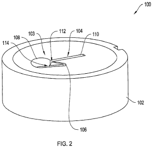
Figure 2 depicts a three-dimensional view of the sample holder 100 of Figure 1
having a channel structure 103 including a sample channel 104 and an overflow
channel 106 according to one illustrative embodiment of the invention. The
channel
structure 103 is shown to be etched within the substrate 102. The sample
channel 104
is connected the overflow channel 106 at overflow connection 112 and pressure
balance
connection 114.
The substrate 102 is cylindrically shaped with a circular top as depicted in
Figure 1 and having a thickness. The substrate 102 may be shaped differently
to fit
within a centrifuge assembly. In certain embodiments, the sample holder 100
may have
a detachable connection with a rotor of the centrifuge. In such embodiments,
substrate
102 may be shaped to fit within the chambers in the rotor.
The substrate 102 may be formed from one or more materials capable of
withstanding centrifugation forces greater than 300,000g. The substrate 102
may be
made of a suitable elastomeric material. Suitable elastomeric materials are
typically
substantially liquid impermeable. Furthermore, suitable substrate 102
materials may be
non-reactive. Non-reactive materials do not react, or only minimally react,
biochemically with a sample. This biochemical non-reactivity is
distinguishable from
adherence that may occur between certain samples and certain materials due,
for
example, to electrostatic interactions. In certain embodiments, the substrate
102
material can be coated with one or more agents. Exemplary agents such as
Teflon help
CA 02655884 2008-12-19
WO 2008/005316 PCT/US2007/015096
13
decrease adherence between the material and the sample. In certain
embodiments, all
or a portion of the substrate 102 can be coated with one or more agents
designed to
promote the stability of the sample. Exemplary agents include, but are not
limited to,
RNase inhibitors to prevent degradation of RNA samples; DNase inhibitors to
prevent
degradation of DNA samples, protease inhibitors to prevent degradation of
protein
samples; anti-microbial agents to prevent microbial infections that can
degrade any
biological sarnple; and anti-fungal agents to prevent fungal infections that
can degrade
any biological sample. For any of the foregoing examples involving the coating
of the
substrate 102 with one or more agents, the systems may include embodiments in
which
the agents are added to the substrate 102 material and incorporated within the
material
during the fabrication process, as well as embodiments in which the substrate
102 that
are coated with agents post-fabrication.
In certain embodiments, the substrate 102 is formed from or coated with a
material that is physically, cheinically or biologically reactive and
particularly
responsive to the sample. Substrate materials may include at least one of
immobilized
ions, antibodies, enzyme substrates, ligands, polyelectrolytes, hydrophobic
matrices.
These materials typically present an immobile phase to which specific
components of
the sample may bind reversibly or irreversibly, and thereby may increase the
time
needed for them to sediment. Substrate materials may be selected based, at
least in part,
on the desired application. Example applications for these surfaces may
include sainple
sub-fractionation, removal of interfering agents and reactive conversion of
sample
components for improved detection.
In one embodiment, the substrate is formed from disposable material. The
material for the substrate 102 may be selected from a group comprising epoxy,
poly-di-
methyl-siloxane (PDMS), polyisoprene, polybutadiene, polychloroprene,
polyisobutylene, poly(styrene-butadiene-styrene), polyurethane, silicon,
poly(bis(fluoroalkoxy)phosphazene), poly(carboranesiloxanes),
poly(acrylonitrile-
butadiene), poly(1-butene), poly(chlorotrifluoroethylene-vinylidene fluoride)
copolymers, poly(ethyl vinyl ether), poly(vinylidene fluoride),
poly(vinylidene
fluoride-hexafluoropropylene) copolymer, polyvinylchloride (PVC), polysulfone,
CA 02655884 2008-12-19
WO 2008/005316 PCT/US2007/015096
14
polycarbonate, polyrnethylmethacrylate (PMMA), polytetrafluoroethylene
(Teflon),
Phenolic Resin and Delrin.
The substrate 102 may further include sensors and identifiers located near the
channel structure 103. In one embodiment, the substrate 102 includes an
identification
panel such as a bar code label to identify the channel structure 103 nearby.
The
substrate 102 may include temperature, pressure and chemical sensors disposed
near
the channel structures 103. The sensors may also be disposed within the sample
channel 104 or the overflow channel 106.
Figure 3 depicts a zoomed-in three-dimensional view of the channel structure
103 having a sample channel 104 and an overflow channel 106 according to one
illustrative embodiment of the invention. In particular, Figure 3 more clearly
points
out some depths and volumes for the channel structures 103 in the sample
holder 100.
In one embodiment, the sample channel 104 has a depth of about lrnm. In other
embodiments, the sample channel 104 may have a depth greater or less than 1mm
depending on the requirements of the particular application. The overflow
channel 106
may be less deep than the sample channel 104. The overflow channel 106 may
have a
depth of about 300 m. The overflow channel 106 may have a depth greater or
less
than 300 m. In one embodiment, the sedimentation region 110 of the sample
channel
104 has a capacity of about 10gL. The overflow channel 106 may have a capacity
of
about 1/2 L. The size, shape and dimensions of the sample channel 104 and the
overflow channel 106 may be chosen based at least in part on the requirements
of the
particular application without departing from the scope of the invention. The
capacity
requirements of the overflow channel may be selected based at least in part on
the
capacity of the pipette used to load the sample into the sample loading region
108. In
one embodiment, channel structure 103 may be formed in a substrate 102 to
create a
sample holder 100. In such an embodiment, during operation, a sample in the
channel
structure 103 can experience centrifugation forces along the length of the
sedimentation
region 110 away from the sample loading region 108. The sample moves into the
sedimentation region 110 until the amount of sample exceeds the sedimentation
region's 110 capacity. Any excess sample then flows into the overflow channel
106
CA 02655884 2008-12-19
WO 2008/005316 PCT/US2007/015096
and creates a meniscus or level at the overflow connection 112. The excess
sample is
allowed to flow into the overflow channel 106 because the pressure in the
overflow is
kept favorable through the pressure balance connection 114.
The movement of the sample in the sample channel 104 in the presence of a
gravitational field generated by a centrifuge may be assisted by the shape of
the sample
channel 104. Generally, rotating centrifuges generate gravitational fields
along a radial
direction away from the center of the axis of rotation. The sample channel 104
may be
shaped to increase or decrease the ease with which the sample moves in the
sample
channel 104 in the radial gravitational field. Figure 4 shows a sample channel
104
having a sector shape to more particularly align with the radial gravitational
field lines.
Figure 4 depicts a top view of a sample holder 400 having a sample channel 404
and an overflow channel 406 formed within a substrate 402 according to another
illustrative embodiment of the invention. The overflow channel 406 is
connected to
the sample channel 404 at the overflow connection 412 along the sedimentation
region
410. The overflow channel 406 is also connected to the sample channel 404 at
the
pressure balance connection 414 along the sample loading region 408. The
sedimentation region 410 is shown to be sector shaped such that the
sedimentation
region 410 tapers near the sample loading region 408. During operation, as the
sample
moves from the sample loading region 408 into the sedimentation region 410, it
generally tends to follow the lines of the gravitational fields along the
radial direction.
The sedimentation region 410 is sector shaped and widens away from the sample
loading region 408. Therefore, as the sample moves through the sedimentation
region
410, it undergoes fewer collisions with the sidewalls. The sample channel 404
and the
overflow channel 406 are formed from similar materials to sample channel 104
and
overflow cliannel 106, respectively of Figure 1.
Figures 5, 6 and 7 depict sample holders and centrifuge assemblies capable of
analyzing a plurality of samples. Figure 5 depicts a three-dimensional view of
a
centrifuge assembly 500 including a plurality of sample holders 100 arranged
in a rotor
502. The rotor 502 is shown to be connected to a shaft 504 such that the rotor
502 and
CA 02655884 2008-12-19
WO 2008/005316 PCT/US2007/015096
16
the shaft 504 rotate in a direction shown by arrow 506. The rotor 502 includes
a
plurality of chambers 508 such that the sample holder 100 removably fits
within the
chamber 508.
The sample holders 100 may be placed in the chambers 508 such that the
sample loading region of the sample channel in the sample holder 100 is closer
to the
shaft 504 and the sedimentation region of the sample channel in the sample
holder 100
is aligned substantially along the radial direction from the center of the
disc shaped
rotor 502. The sample holders 100 may be placed in other orientations
depending on
the requirements of the specific application.
The rotor 502 is shown to be disc shaped and having chambers 508 to
accommodate the sample holders 100. The rotor 502 may be formed from rigid and
resilient material including titanium and epoxy composites.
Figure 6 depicts a top view of a sample holder 600 having a plurality of
sample
channels 602 according to one illustrative embodiment of the invention. In
particular,
the sample holder 600 is shown to include a ring shaped substrate 602 having
about
ninety-six channel structures 603. The sample holder 600 may be similar to
sample
holder 100 of Figure 1. The substrate 602 may be formed from similar materials
to
substrate 102 of Figure 1. The channel structures 603 are formed similarly to
channel
structures 103 of Figure 1. The sample holder 600 may be sized and shaped to
fit
directly with a rotor of a centrifuge. In some embodiments, the sample holder
600 anay
be fonned from resilient materials such that it may function as a rotor in the
centrifuge.
In such embodiments, the sample holder 600 is configured to couple to a shaft
of the
centrifuge. In certain embodiments, the sample holder 600 is sized and shaped
to
couple indirectly to a rotor of a centrifuge
Figure 7 depicts a three-dimensional view of a centrifuge assembly 700
according to another illustrative embodiment of the invention. The assembly
700
comprises a sample holder 701, a rotor 706 and a sleeve 704 attached
therebetween.
The sleeve 704 helps attach the sample holder 701 to the rotor 706. The sample
holder
CA 02655884 2008-12-19
WO 2008/005316 PCT/US2007/015096
17
includes a substrate 702 having one or more channel structures 703 formed
therein.
The sample holder 701, the sleeve 704 and the rotor 706 are coupled to a
centrifuge
shaft 708 such that they may rotate about the shaft in directions shown by
arrow 710.
The sample holder 701 may be similar to sample holder 100 of Figure 1. The
substrate 702 may be formed from similar materials to substrate 102 of Figure
1. The
channel structures 703 are formed similarly to channel structures 103 of
Figure 1. In
one embodiment, the sample holder 701 has a plurality of channel structures
703,
similar to the sample holder 600 of Figure 6.
The sleeve 704 may be sized and shaped to accommodate the sample holder 701
and fit securely onto the rotor 706. The sleeve 704 may be formed from
suitable rigid
materials including titanium.
The sample holder of Figure 1-7 may be used together with a suitable
luminescence based measurement system in a centrifuge to study the temporal
variations of the concentration distribution in a sample.
Figure 8A - 8C depict a channel structure 103 and the movement of the sample
from the sample loading region to the sedimentation region along with the
overflow of
any excess sample into the overflow region. In particular, Figure 8A shows the
sample
802 substantially in the sample loading region 108 and a partially in the
sedimentation
region 110. During the operation of a centrifuge, the sample 802 flows from
the
sample loading region 108 to the sedimentation region 110. The sample 802
fills the
sedimentation region and overflows in to the overflow channel 106. Figure 8B
shows
the sedimentation region 110 filled with sample 802. The meniscus of the
sample 802
coincides with the overflow connection 112. Any excess sample 802 from the
sedimentation region flows into the overflow channel 106.
As the centrifuge operates, generating more gravitational forces on the sample
802, the solute 806 and the solvent 804 in the sample 802 begin to separate.
Figure 8C
shows the separation of the solvent 804 and the solute 806 in the
sedimentation region
CA 02655884 2008-12-19
WO 2008/005316 PCT/US2007/015096
18
110. As centrifugation continues, the solute 806 begins to sediment at one end
of the
sedimentation region 110. The meniscus 808 is maintained near the overflow
connection 112 while the solute boundary 810 moves away from the sample
loading
region 108.
Figure 8D depicts a chart 812 of absorbance measurements of the sample 802 at
a particular time instant during centrifugation according to one illustrative
embodiment
of the invention. The horizontal axis 814 represents the radial distance from
the center
of the axis of rotation of the centrifuge. The vertical axis 816 represents
the absorbance
reading obtained from the sample 802 during the centrifugation process. In
particular,
during centrifugation, the sample is illuminated with light having one or more
wavelengths and the light absorbed by the sample is measured as absorbance.
The
absorbance metric helps provide a measurement of the concentration of the
substance at
various radial locations. The absorbance curve 818 corresponds to the
concentration
distribution of the sample 802 in the sedimentation region 110 of the sample
holder
102. The absorbance curve 818 includes a some spikes in measurement near the
location of the meniscus 808. The absorbance curve 818 also depicts the
sedimentation
boundary 820. An advantage of the invention is that the meniscus 808 and the
related
spike 822 in the absorbance measurement are relatively fixed and therefore
reliable
measurements can be made to automatically determine the exact meniscus
location
with little or no human involvement.
Figure 9 depicts a more detailed plot 900 of the absorbance versus the radial
distance according to one illustrative embodiment of the invention. The plot
900 may
be used to calculate the sedimentation velocity of the solute 806. In
particular, the
horizontal axis 902 shows the radial distance from the center of the axis of
rotation and
the vertical axis 904 shows the value of absorbance. Each of the curves 906
show the
value of absorbance being measured at the various locations along the radial
direction.
The plurality of curves 906 represent absorbance measurements taken along the
lengtli
of the sample channel 104 at a plurality of instances in time. The
characteristic shape
of the sedimentation curve 906 depicts an increased absorbance in the region
of the
solute 806 and a low absorbance in the region of the clear solvent 804. The
CA 02655884 2008-12-19
WO 2008/005316 PCT/US2007/015096
19
sedimentation boundary 912 is the region between the high absorbance
measurements
and the low, almost zero, absorbance measurements. During the centrifugation
process,
the sedimentation boundary 912 (or solute boundary 810) moves away from the
meniscus 808. The meniscus 808 is identified in the absorbance curve 906 as
spike
910. In certain embodiments, a reference channel containing a solvent 804 may
be
included in the sample holder 100. The meniscus of the reference channel
solvent may
also be identified in the absorbance curve as spike 908. In other embodiments,
the
spikes 908 and 910 may overlap.
As noted earlier, the boundary 912 tends to move along the radial
direction as time passes. The rate at which the sedimentation boundary 912
moves is
typically a measure of the sedimentation coefficient of the solute. The
sedimentation
coefficient typically depends on the molecular weight (larger molecules
typically
sediment faster) and also on molecular shape, size and concentration. As an
example,
unfolded proteins or proteins with elongated shapes generally experience more
hydrodynamic friction, and thus have smaller sedimentation coefficients than a
folded,
globular protein of the similar molecular weight. In one embodiment, the slope
of the
boundary 912 may decrease with the passing of time. In such embodiments, the
boundary region 912 tends to become wider resulting in boundary spreading. The
rate
of boundary spreading typically helps yield the diffusion coefficient of the
solute in the
sample. Additionally the rate of boundary spreading may be influenced by the
presence
of multiple solute species with similar sedimentation coefficients. This
generally
causes the boundary 912 to become broader than expected on the basis of
diffusion
alone.
In general, absorbance measurements use the absorbance of a solute to
determine the temporal variation of its concentration along a sample channel
104. In
certain embodiments, fluorescence and refractive measurements are also used to
determine the temporal variation of concentration along a sample channel 104.
Such
light based measurement techniques typically require visual inspection of the
sample
during measurement. In particular, light beams have to impinge on the sample
and the
light emitted from the sample has to be collected. Sample holders 100 may be
CA 02655884 2008-12-19
WO 2008/005316 PCT/US2007/015096
assembled with transparent windows to allow light to pass through and from the
sample.
Figure 10 depicts an assembly of a sample holder and a window according to
one illustrative embodiment of the invention. The assembly 1000 shows a sample
holder 100 formed from a substrate 102 being attached to a window 1002. In one
embodiment, the window 1002 is hermetically sealed to the top of the substrate
102
such that the sample channel 104 and the overflow channel 106 are sealed. In
certain
embodiments, the window 1002 includes an optically inert plastic material. In
another
embodiment, the window 1002 includes rigid transparent materials such as
quartz,
sapphire and glass.
The window 1002 may be sized and shaped to fit on top of the substrate. In
some embodiments, the window 1002 may cover a portion of the substrate 102. A
plurality of windows 1002 may be used either on top of the substrate 102,
below the
substrate 102 or both above and below the substrate 102. The transparent
window
functions to keep the sample within the sainple channel 104 during
centrifugation as
well as allow for luminescence measurements to be made on the sample as
described
further in Figure 11.
Figure 11 depicts a system for fluorescently detecting a species in a sample
using a sample holder and a fluorescence measurement system 1100 according to
one
illustrative embodiment of the invention. The system 1100 includes an optical
system
1102 having a light source 1104, a mirror 1106, a beam splitter 1108, a filter
bank 1110
and a photomultiplier tube (PMT) 1112. The optical system 1102 is connected to
a
computer terminal 1114 that operates the light source 1104, receives data from
the
PMT 1112 and controls the position of various optical elements. Beams
originating
from the light source 1104 in the optical system 1102 are directed using
mirror 1106
and beam splitter 1108 towards the sample located within the sedimentation
region 110
of the sample holder 100. The beam impinges on the sample at measurement
position
1116. One or more sample holders 100 may be configured within the rotor 502
and
therefore one or more sample may be observed and analyzed while the centrifuge
CA 02655884 2008-12-19
WO 2008/005316 PCT/US2007/015096
21
operates and the rotor spins. The light emitted from the sample then passes
through the
beam splitter 1108 and into a filter bank 1110 to further refine the quality
of the signal.
The filtered optical signal is detected at the PMT 1112 and then sent to a
computer
terminal 1114 for processing.
In one embodiment, the optical measurement system uses co-axial excitation
and emission similar to confocal fluorescent microscopes. Therefore, in other
embodiments, the optical measurement system 1100 may be replaced by a confocal
fluorescent microscope without departing from the scope of the invention.
In one embodiment, the light source 1104 includes a laser. The laser may be a
continuous 50mW Ar laser tuned to about 488nm. One example of such a laser is
a
532-AP-OAR-AAM laser manufactured by Omnichrome, Inc., Carlsbad, CA. The
light source may also include a Xenon light source. In certain embodiments,
the light
source 1104 includes a pulsed light source. In other embodiments, the light
source(s)
1104 may include an arc lamp, an incandescent bulb which also may be colored,
filtered or painted, a lens end bulb, a line light, a halogen lamp, a light
emitting diode
(LED), a chip from an LED, a neon bulb, a fluorescent tube, a fiber optic
light pipe
transmitting from a remote source, a laser or laser diode, or any other
suitable light
source. Additionally, the light sources 1104 may be a multiple colored LED, or
a
combination of multiple colored radiation sources in order to provide a
desired colored
or white light output distribution. For example, a plurality of colored lights
such as
LEDs of different colors (red, blue, green) or a single LED with multiple
colored chips
may be employed to create white light or any other colored light output
distribution by
varying the intensities of each individual colored light. The light source
1104 may be
coupled into an optical fiber which delivers the light to the remaining
optical elements
in the optical system 1102. The optical fiber includes a 3.5 m glass, single-
mode fiber
such as a SMJ-33-488-3.5/125-3-5-SP manufactured by Oz Optical, Ottawa,
Ontario,
Canada.
The tip of the optical fiber is typically located at the focal point of a
collimating
lens. Excitation light from the light source 1104 generally spreads into a
cone that is
CA 02655884 2008-12-19
WO 2008/005316 PCT/US2007/015096
22
collimated using the collimating lens. The collimated beam of excitation light
is then
directed towards the mirror 1106. In one embodiment, the mirror is a silver
elliptical
mirror that may be optionally attached to an adjustable mirror holder. The
mirror 1106
redirects the beam of excitation light towards the beam splitter 1108.
In one embodiment, the beam splitter 1108 includes a dichroic beam splitter
attached to an adjustable mirror holder. The dichroic beam splitter 1108
selectively
reflects light below a certain wavelength while passing light from the
remaining
wavelengths. In one einbodiinent, the dichroic beam splitter 1108 reflects
about 95%
of the light at wavelengths shorter than about 490 nm. The beam of excitation
light is
reflected by the dichroic beam splitter and directed towards the sample holder
100. In
one embodiment, a condenser lens is placed between the beam splitter 1108 and
the
sample holder 100 such that the excitation light is focused on the sample
holder 100.
The condenser lens may also serve as an objective lens to receive light
emitted by the
sample in response to the impinging excitation beam of light.
The fluorescing sample may emit light in a plurality of directions at
typically
longer wavelengths than the beam of excitation light. Light emitted from the
sample is
collimated by an optional objective lens (e.g., the condenser lens) and passed
through
the beam splitter 1108.
The-collimated emission light may be refocused and passed through a filter
bank I 1 10. In one embodiment, the filter bank 11 10 includes long-pass
filters having
greater than 95% transmittance at wavelengths greater than 505 nm. The filter
bank
1110 also includes spatial filters positioned near to the PMT 1112.
The PMT 1112 converts the emission beam in the form of optical signals to
electrical signals. Therefore, any detector capable of converting optical
signals to
electrical signals may be used as a PMT 1112 without departing from the scope
of the
invention. In certain embodiments, the detector may include at least one of a
charge
coupled device (CCD), a CMOS detector and a photodiode.
CA 02655884 2008-12-19
WO 2008/005316 PCT/US2007/015096
23
Electrical signals from the PMT 1112 may initially be processed by electronics
for buffering, amplification and signal conditioning. The electronics may be
integral
within the computer terminal 1114. The computer terminal 1114 may also include
other electronic circuitry to digitize and store the analog electrical signals
received from
the PMT 1112. The computer terminal 1114 may include any computer system
having
a microprocessor, a memory and a microcontroller. The memory typically
includes a
main memory and a read only memory. The memory may also include mass storage
components having, for example, various disk drives, tape drives, etc. The
mass
storage may include one or more magnetic disk or tape drives or optical disk
drives, for
storing data and instructions for use by the microprocessor. The memory may
also
include one or more drives for various portable media, such as a floppy disk,
a compact
disc read only memory (CD-ROM), or an integrated circuit non-volatile memory
adapter ( i.e. PC-MCIA adapter) to input and output data and code to and from
microprocessor. The memory may also include dynamic random access memory
(DRAM) and high-speed cache memory.
In one embodiment, the computer terminal 1114 includes data acquisition
circuitry capable of being synchronized with the rotor of the centrifuge. In
such an
embodiment, the rotor may include Hall Effect sensors capable of generating
rotor
timing pulses. The leading edge of these rotor timing pulses clocks an
electronic circuit
whose output may be a square wave with a period equal to one revolution of the
rotor.
The square wave provides a gating signal for data acquisition. In one
embodiment,
digitized signals are acquired into a data storage module. In such
embodiments, an
additional pre-triggering circuit enables storage of data digitized for a
period preceding
the edge of the gating signal, thereby ensuring that data are obtained from a
complete
rotation. The computer terminal 1114 includes software to allow for data from
several
consecutive turns of the rotor to be accumulated in the memory module.
The computer terminal 1114 may be connected to operate the light source in
either a continuous mode or a pulsed mode. The computer terminal 1114 may also
be
connected to other optical elements within the optical system 1102 including
the
adjustable mirror holders supporting the mirror 1106 and the beam splitter
1108.
CA 02655884 2008-12-19
WO 2008/005316 PCT/US2007/015096
24
As noted above, the light source 1104 in the fluorescent measurement system
1100 may be operated in a continuous mode or in a pulsed mode or a combination
thereof. The choice of mode may depend at least from the requirements that the
signal
received has to be synchronized with the spinning rotor and signals from
different
sample have to be isolated from one another. One mode may be selected over
another
based at least in part on quantity and quality of data desired. In one
embodiment, the
light source 1104 is operated in continuous mode and the signals from
different
samples are separated from one another by synchronizing the detector with the
spinning
motor. A multiplexing circuit may be employed to separate portions of the
detector
signal corresponding to moments when a particular sample is in the light beam.
In
another embodiment, the light source 1104 is operated in a pulsed mode. In
such an
embodiment, the pulsed light source 1104 is triggered when a sample is aligned
with
the detector. In another embodiment, the light source and detector are
operated in a
continuous manner, with the detector data stored in computer memory, and the
signals
from the samples separated by software.
In certain optional embodiments, the optical system 1102 can be mounted on
any suitable stepping motor-driver stage. Such a stage may be controlled by
the
computer terminal 1114 using a stepping motor controller. The optical system
1102
and the stepping motor stage may attach to two or more mounting posts that are
mounted to a base plate of an optional vacuum chamber of the centrifuge. In
certain
embodiments, the posts may be designed to allow the entire optical system 1102
to be
removed and replaced in the vacuum chamber while minimizing positional
accuracy.
With such.a movable optical system 1102, the fluorescent measurement system
1100
may be configured to perform a radial scan of the sample channel 104 during
operation.
The fluorescent measurement system 1100 may be particularly useful in
measuring trace quantities of solute in a solvent. A small amount of solute
may be
fluorescently labeled and its boundary may be tracked in such a system as
described
above. The fluorescent measurement system 1100 may also be useful in tracking
a
particular species within a sample that contains a large number of species. In
samples
CA 02655884 2008-12-19
WO 2008/005316 PCT/US2007/015096
with a large number of species (e.g., blood =having a plurality of proteins),
sedimentation velocity experiments are difficult to perform because the
sedimentation
boundaries are typically blurred and difficult to track. In such samples, the
species of
interest have to be tracked separately.
In tracking individual species in a sample having a complex mixture of
species,
the characteristics of the species may be estimated based at least on the
velocity of the
sample. The velocity of the species may be calculated based on the time taken
for the
species to travel from one position on the sedimentation region 110 of the
sample
channel 104 to another position. In one embodiment, the initial position of
the species
is fixed at the meniscus position 808 determined by the overflow connection
112. A
second position of the species may be adjustably selected as the measurement
position
1116. The measurement position 1116 is controlled by the operation of the
fluorescent
measurement system 1100. During centrifugation and sedimentation, the species
may
move from the initial position determined by the location of the meniscus to a
second
position determined by the location of measurement. The tiine taken for the
species to
travel this distance may be calculated and used to determine the velocity of
the species.
The velocity of the species can be defined in terms of a sedimentation
coefficient, S,
given by the formula:
ln measurement position
S meniscus position
=
C()Zt
where ao is angular velocity of the centrifuge rotor and t is the time taken
for the
species to travel from the meniscus position 808 to the measurement position
1116,
measurement position is the radial distance from the center of the axis of
rotation of the
centrifuge to the measurement position 1116 and meniscus position is the
radial
distance from the center of the axis of rotation of the centrifuge to the
meniscus
position 808.
CA 02655884 2008-12-19
WO 2008/005316 PCT/US2007/015096
26
One or more measurement positions 1116 may be implemented to calculate the
sedimentation velocity of a species in a sample. Figure 12 depicts a system
1200 for
fluorescently detecting a species in a sample at two radial locations
according to one
illustrative embodiment of the invention. In particular, the fluorescence
measurement
system 1200 includes two optical systems 1202a and 1202b fixed at two
locations
along the length of the sample channel 104. The two locations represent
measurement .
positions 1204a and 1204b for each the optical systems 1202a and 1202b,
respectively.
The optical systems 1202a and 1202b are similar to optical system 1102 of
Figure 11.
During operation, the sedimentation velocity of a species in a sample can be
calculated
based on the time taken for the species to travel from one measurement
position 1204a
to another measurement position 1204b. The sedimentation velocity obtained
from
such a calculation can be compared to the sedimentation velocity obtained
using the
meniscus position 808.
The sedimentation coefficient may be used to determine, among other things,
the molecular mass of the species, the size of species, the shape of the
species and the
concentration of the species. The fluorescent measurement system 1100 of
Figure 11 in
combination with the meniscus defining sample holder 100 in a centrifuge may
be used
for clinical diagnostics to study certain samples such as blbod and detect the
presence
of certain species present in these samples.
Direct Dye-Labeling
In one implementation, a labeling agent such as a luminophore may be added to
the sample to form a tagged sample. The luminophore may bind itself to a
species in
the sample. In certain embodiments, the sample includes at least one of blood,
protein,
cerebral spinal fluid, nucleic acid, urine and sputum. The species of
interest, in such
embodiments, may be a protein such as a beta-amyloid protein (commercially
available
beta-amyloid 142). The luminophore may include at least one of Green
fluorescent
protein, Texas Red, Fluorescein, Coumarin, Indian Yellow, Luciferin,
Rhodamine,
Perylene, Phycobilin, Phycoerythrin, Umbelliferone, Stilbene, Alexa Fluor,
Oregon
Green, HiLyte Fluor, Th-T, DCVJ and quantum dots.
CA 02655884 2008-12-19
WO 2008/005316 PCT/US2007/015096
27
A centrifuge having a meniscus defining sample holder 100 and a fluorescence
measurement system 11001ocated at a fixed radial distance along the
sedimentation
region 110 of the sample channel 104 may be used to detect a species in the
tagged
sample. The centrifuge may be operated such that the sample placed in the
sample
loading region 108, flows into the sedimentation region 110 of the sample
channel and
any excess sample flows into the overflow channel 106. A fixed meniscus
position 808
may be obtained near the overflow connection 112. As the centrifuge spins, the
individual species within the sample including the tagged species may then
begin
moving away from the meniscus position 808. Luminescence (e.g., fluorescence,
phosphorescence, chemi-luminescence) may be measured at the measurement
position
1116 and a change in luminescence may be detected when the tagged species
crosses
the measurement position 1116. The velocity of the tagged species may be
calculated
based, at least in part, on the time taken for the species to travel from the
meniscus
position 808 to the measurement position 1116. The size, shape, molecular mass
and
concentration of the species may also be identified from the calculated
velocity.
. Such an implementation, may be useful in clinical diagnostics to diagnose
neurodegenerative diseases including Alzheimer disease, Creutzfeldt-Jakob
disease
(CJD), bovine spongiform encephalopathy (BSE), Alexander disease, Alper's
disease,
Amyotrophic lateral sclerosis, Ataxia telangiectasia, Batten disease (also
known as
Spielmeyer-Vogt-Sjogren-Batten disease), Canavan disease, Cockayne syndrome,
Corticobasal degeneration, Huntington disease, Kennedy's disease, Krabbe
disease,
Lewy body dementia, Machado-Joseph disease (Spinocerebellar ataxia type 3),
Multiple sclerosis, Multiple System Atrophy, Parkinson disease, Pelizaeus-
Merzbacher
Disease, Pick's disease, Primary lateral sclerosis, Refsum's disease, Sandhoff
disease,
Schilder's disease, Spinocerebellar ataxia (multiple types with varying
characteristics),
Spinal muscular atrophy, Steele-Richardson-Olszewski disease, Tabes dorsalis.
CA 02655884 2008-12-19
WO 2008/005316 PCT/US2007/015096
28
Detection of Antibodies and Antigens
In another implementation, an agent such as an antibody that is bound to a
labeling agent such as a luminophore may be added to the sample to form a
tagged
sample. In such an implementation, the agent-luminophore combination may bind
itself to a species in the sample. During operation of the centrifuge, the
velocity (or
sedimentation coefficient) of the species may be identified from the measuring
the time
taken to travel from the meniscus position 808 to the measurement position
1116 where
the agent-luminophore combination bound to the species can be detected by the
fluorescence measurement system 1100.
A similar implementation involves the addition of an agent (peptide,
nucleotide,
saccharide, lipid) labeled with a luminophore. The agent is or mimics an
antigen that
can bind to an unlabeled antibody. Such an implementation may be used to
detect
antibodies that are produced as part of a disease state or to demonstrate the
lack of
antibodies which is diagnostic of other disease states.
The implementations described herein may be used to detect antigens in a
sample that provoke an immune response such as infectious agents, allergens,
auto-
antibodies. Antigens may include bacteria, viruses, protozoa and amoeba. The
agent
may include an antibody that preferentially binds to a particular antigen. The
invention
may be used in clinical diagnostics to diagnose at least H.l.V., Hepatitis A,
B and C,
and Rheumatoid Arthritis. In one implementation, the invention may be used to
diagnose cancer.
Those skilled in the art will know or be able to ascertain using no more than
routine experimentation, many equivalents to the embodiments and practices
described
herein. Accordingly, it will be understood that the invention is not to be
limited to the
embodiments disclosed herein, but is to be understood from the following
claims,
which are to be interpreted as broadly as allowed under the law.