Note: Descriptions are shown in the official language in which they were submitted.
CA 02656059 2008-12-22
WO 2008/002426 PCT/US2007/014338
TITLE OF THE INVENTION
Branched Stent Delivery System
BACKGROUND OF THE INVENTION
The present invention generally relates to a delivery system and method
for delivering an expandable endoluminal prosthetic device such as a stent
graft and more particularly to a device and method for placing an acutely
angled bifurcated stent graft through a single access incision. Expandable
surgical devices such as stents or stent grafts are used in a variety of
places in
the human body to repair aneurysms and to support various anatomical
lumens, such as blood vessels, respiratory ducts, gastrointestinal ducts, and
the like.
Conventionally, these devices are deployed across an aneurysm or in
the regions of a stenosis in the target body lumen to repair the aneurysm or
to
hold the lumen open. Because stent graft implantation is a relatively non-
invasive procedure, it has been proven to be a favorable alternative to
surgery
in, for example, the repair of an aneurysm. Bifurcated devices with their
trunk
and branching configuration are particularly well suited for use in branching
body lumen systems, such as in the coronary vasculature, and the peripheral
vasculature. The coronary vasculature includes the right, left common, left
anterior descending and circumflex arteries and their branches. The peripheral
vasculature includes branches of the carotids, aorta, femoral, popliteal,
internal
iliac, or hypergastric and related arteries. Placement of such a bifurcated
device can be rather complicated, and often involves approaching the
bifurcated section of the artery through at least two side branches or through
the trunk plus one side branch. The procedure is not only time consuming, but
can also lead to more incision sites in the patient's body and can necessitate
more complicated maneuvers for the surgeon. These complications are further
exaggerated when an acutely angled or reverse direction side branch is
accessed, as for example a repair of the hyporgastric artery. US Patent No.
6,645,242 teaches a bifurcated intravascular stent graft comprising primary
stent segments and a primary graft sleeve forming a main fluid channel and
having a side opening therethrough.
However, there exists a need for a stent graft delivery system which
would allow placement of bifurcated stent grafts into acutely angled
vasculature
CA 02656059 2008-12-22
WO 2008/002426 PCT/US2007/014338
such that simpler surgical procedures are enabled. A simplified surgical
procedure would decrease the number or size of incisions, reduce the required
surgical steps, and thereby reduce patient trauma associated with a more
complex medical procedure.
SUMMARY OF THE INVENTION
The present invention further provides an interventional delivery system
comprising: a first catheter having at its distal end a side branch vessel
segment; a second catheter attached around the first catheter and having at
its
distal end a main vessel segment; and a side branch vessel device attached to
the side branch vessel segment of the first catheter wherein the main vessel
segment and the side branch vessel device are simultaneously delivered to a
treatment site, and further wherein the second catheter has an opening in a
side wall near the distal end of the second catheter to allow for passage of
the
side branch vessel segment of the first catheter. The second catheter may
comprise a capture tube which surrounds the bifurcated guidewire and
facilitates for the ease of bifurcated guidewire removal from a vessel. A
bifurcated guidewire with at least two distal tips may be used with the first
catheter. The two distal tips face opposing directions, wherein one of the two
distal tips is the leading end and one of the tips is a reverse facing tip
end.
The present invention further provides a first catheter having at its distal
end a side branch vessel segment; a second catheter attached around the first
catheter and having at its distal end a main vessel segment; a side branch
vessel device attached to the side branch vessel segment of the first
catheter;
and a main vessel device attached to the main vessel segment of the second
catheter. The main vessel device and the side branch vessel device are
simultaneously delivered to a treatment site.
A method of deploying a branched stent assembly is also provided
comprising: advancing a catheter assembly on a bifurcated guidewire to a
treatment site; orienting the catheter assembly in the main vessel; pulling
the
bifurcated guidewire to orient the. guidewire reverse facing tip into the side
branch vessel; deploying the main vessel device in the main vessel; then
advancing the side branch vessel device to a desired location; and deploying
the side branch device. After stent deployment, removal of the delivery
assembly is facilitated by advancing the guidewire and first catheter forward
until the guidewire reverse facing tip and reverse facing portion of the first
2
CA 02656059 2008-12-22
WO 2008/002426 PCT/US2007/014338
catheter are retracted from the side branch vessel allowing removal of the
bifurcated guidewire along with the first and second catheters.
DESCRIPTION OF THE DRAWINGS
Figure 1 shows the interventional delivery system comprising a first
catheter and a second catheter upon insertion in a vessel.
Figures 2A and 2B show the first catheter of the interventional delivery
system. Figure 2A depicts a bent shaft configuration and Figure 28 depicts a
shaft configuration using a connector.
Figure 3 shows the bifurcated guidewire assembly with a leading
segment and a reverse facing segment.
Figure 4A shows a first catheter with a bent shaft and apex opening for
the bifurcated guidewire with a side branch device mounted on the side branch
vessel segment of the first catheter shaft.
Figure 4B shows a first catheter with a shaft configuration using a
connector for the bifurcated guidewire with a side branch device mounted on
the side branch vessel segment of the first catheter shaft.
Figure 5 shows an enlarged view of the side branch vessel segment
with a side branch vessel device mounted and constrained within a sheath.
Figures 6A and 6B show side views of a second catheter with a side
branch opening.
Figure 7 is an isometric view of an expanded main body stent graft.
Figure 8 is a partial cross-sectional view of a main body stent with a
bifurcated guidewire and a first catheter with a side branch device.
Figure 9 is a partial cross-sectional view of a main body stent with a
bifurcated guidewire and a first catheter with a side branch device contained
in
a second catheter. Also shown is a constraint sheath over the main body stent
and the apertures in the main body stent and the constraining sheath.
Figures 10A and 10B show partial cross-sectional views of the distal
device portion and the proximal hub portions of the interventional delivery
system of the present invention. The distal device portion is positioned
within a
main vessel adjacent to a branched vessel.
Figures 11A and 11 B show partial cross-sectional views of the distal
device portion and the proximal hub portions of the interventional delivery
system of the present invention. The reverse facing guidewire is shown being
advanced into the side branch, acutely angled vessel.
3
CA 02656059 2008-12-22
WO 2008/002426 PCT/US2007/014338
Figures 12A and 12B show partial cross-sectional views of the distal
device portion and the proximal hub portions of the interventional delivery
system of the present invention. The main body stent is shown in an expanded
state.
Figures 13A and 13B show partial cross-sectional views of the distal
device portion and the proximal hub portions of the interventional delivery
system of the present invention. The reverse facing segment of the first
catheter with a constrained side branch device is shown being advanced into
the side branch, acutely angled vessel.
Figures 14A and 14B show partial cross-sectionai views of the distal
device portion and the proximal hub portions of the interventional delivery
system of the present invention. The side branch stent is shown in an
expanded state.
Figures 15A and 15B show partial cross-sectional views of the distal
device portion and the proximal hub portions of the interventional delivery
system of the present invention. The reverse facing portion of the first
catheter
and the guidwire are shown being advanced into a capture tube.
Figures 16A and 16B show partial cross-sectional views of the distal
device portion and the proximal hub portions of the interventional delivery
system of the present invention. The first catheter, the second catheter, and
the guidewire are shown being withdrawn from the treatment site.
DETAILED DESCRIPTION OF THE INVENTION
The present invention provides an interventional delivery system for the
placement of bifurcated stent grafts into acutely angled vasculature. Acutely
angled vasculature may exist in renal vessels, subclavian arteries, biliary
ducts,
prostate vessels, and other non-vascular applications as well. The challenge
in
stent placement is deployment from a main vessel such as a femoral artery to a
reverse acute angle vessel. The present invention provides a device and
procedure which decreases the number and size of incisions required to place
bifurcated stent grafts into acutely angled vasculature, and further reduces
the
required surgical steps and patient trauma associated with this traditionally
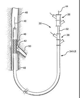
more complex medical procedure. As shown in Figure 1, the present invention
provides an interventional delivery system 30 comprising a first catheter
shaft
32, a second catheter assembly 34A or 34B, a first catheter hub assembly 36,
4
CA 02656059 2008-12-22 .
Tn~ 23 01 i 2008 23 2~2B 12: 54 FR WL GQRE LEGAL DEPT 302 292 4153 TO 901
131703403016 a(O =l t
-- . .
. US2007014338
,
.
aseeond catheter t-ub assembly 3$, a bifurcated guidewire leadin8 tip 40, a
bifurcated guidewire reverse facing tip 42, a bifurcated guidewire proximal
tip
44, and a device aasembly 46, The interventional delivery system 30 is shown
pesitioned ir1 an anatomical main vessel 48 so that the device assembly 46 is
positianed approximate to an anatornical side branch ve5sel 50. As described
. in subsequent tigures, the device assembly 48 will be deployed to form a
main
body sterit within the main vessel 48 ~long with an integrated side branch
stent
within the side branoh vessel 50
.
Shawn in Figures 2 through 9 are various sub-components and
assernhlies of the interventional delivery system 30 (of Figure 1 ). Shewn in
Figure 2A ia a first catheter assembly 52A having a first catheter hub
assembly
36. The hub assemhly 36 includes a perfusion port 54, a bifurcated guidewire
port 56, a aade branoh deployment line 55 protruding ffom a deployment line
port 60. The first catheter assembfiy 52A further cornprises a first oatheter
shaft
32 that has an apex epening 62A. Apex operiing 62A as shown is a Gut-
opening through the wall of the first catheter shaft 32. The first catheter
shaft
is shown hent about the apex opening 62A, forming ~ reverse facing segment
64. The reverae facirrg aegrnent 64 has a side br9nch devioe pertien 66 and a
side branch device to apex opening separation length 68.
As ahown in Figure 2B a first catheter assennbly 828 has afirst oatheter
hub assembly 36. The hub assembly 36 includes a perfusion port 54, a
aifurcated guidewire port 56, aside branch deployment line 88 protruding from
a deployment iine port 60. The first catheter assembly 52B further comprises a
first catheter shaft 32 that has an apex opening 62B. Apex opening 628 as
shown cQmprises the open ends of acut catheter shaft 32. The two cut ends
are joined at cannection 70. The two cut shafts es shown forrn a r~everse
facing
segment 64. The reverse facing segment 64 has a side branch deviee portion
86 and aside branch devi+ce to apex opening separatien length 68.
Depioted in Figure 3 is a bifurcated guidewire assembly 72 heving a
' 30 proximal tip 44 and a main segrnent 76. vVithin the distal portion of the
~
guidewire mair~ segment 75 is a connec#ion 78, definirtg a leading 9uidewire
.
segrr~er~t ~0 and a reverse faoing guidewire segment 82. The Ieading
. guidewire segment has a proximal tip 44 and the reverse facing guidewire
aegment has a reverse facing tip 42.
Figure 4A shows a first catheter assembly (52A af Figure 2P-) combined
with a bifurcated guidewire assembly (72 ef Figure 3), Referring to Figures
2A,
3, ar7d 4A, shown is abifurcated guidewire assembly 72 positioned within a
first
5 =
~eceived at the EPQvn Jan 23, 200818:36:35, Pa AM DED
EN SHEET
= CA 02656059 2008-12-22 . )
^ r.n . e n
23 2008 12 : 54 FR WL GQRE LE~AL DEF'T 302 292 4153 Tfl 9@1 1317@34@3@16
23-01-2008 . US2
OO1014338
' catheter assembly 52A, 3hown protruding frorn an apex opening 62A is tha
hifurcated guid~wire connection 78 along with the leadlng guidewire segment
. 80, Yhe proxlmal end 74 of the bifurcated guidewire protrudes from the
bifurcated guidewire port 56 and the reverse facing tip 42 of the guidewire
8 protrudes frorn the reverse facing $?gment of the fira# cath$ter.
.Sirnilarly, Pigure 46 shows a preferred first catheter assembly (52B of
E'igure 25) combinad with a bifurcated guidewire aasembly (72 of I~`igure 3).
. Referring to Pfgures 2B1 3, and 48, shown is a bifurcated guidewire
assernhiy
72 positioned wifhin a frst catheter assernbly 52B. Shown protruding from an
1 0 apex opening 62B is the bifurcated guidewire connection 78 alcng with the
leading guidewire segrnent 84, The proxirrtal end 74 of the bifurcated
guidewire protrudes from the bifurcated guidewire pork 56, and the reverse
facing tip 42 of the guidewire protrudes from the reverse facing segment of
the
firatbatheter. The tube-to~tube connectiort 70 can include a friction-reducing
I 5 ecmponent or feature ta aIlaw the deployment line 58 to easily slide
ag3inst the
tubes or apex opening as the deployrnent line is activated.
. $hown in Figure 5 are a partial crdSs-seGtional view of the reverse
facing segment 64 tha# includes aside branch device portion 66 and aside
~
~ branch device tc apex opening separation Iength 68. Shown is the b'tfurcated
~
20 guidewire 72 reverse facing tip 42 exitin0 frnm an olive 88. Positioned
onto a
! side branch auccmmodating segrnent 94 ia a constraEned, salf-expanding side
branch device 90. Tha eide branch device 90 is he{d in a cornpressed state by
a canstraining sheath 92. Attached cr integral to the constraining sheath is a
side branch device deployment line 58.
25 Figures 6A and G~ are side views cf two embadiments of a second
~ catheter, Showrt in Eigure 6A is asecond eatheter assembEy 34A having a
. second catheter hub assembly 3$. The ~econd catheter hub asaembly further
includes a praximal perfusion port 54. The hub as5embly ia joined th a second
catheter main body 96. Near the distal end of the second catheter rnain body
30 90 is a side branch device opening 98, forrned by a cut-out portion of the
catheter wall. The opening 98 aliows a bifurcated guidewire and aside branch
device tn be subsequently advanced from the second eatheter. After
depioyrnent, the bifurcated guidewire can be pulled through the opaning 98
into
the seeond catheter for removal. At the dista1 end of the second catheter main
35 body is a capture tube p4rtion 100. This tube portion "captures" the
bifurcated
guidewire after device deployment, allowing far a non-traumatic rernoval af
the
guidewire and delivery systcm. ,
6
Received at the EPO on Jan 23, 2008 1 8:36:35. Pa
AMENDED SHEET
CA 02656059 2008-12-22
WO 2008/002426 PCT/US2007/014338
Simitarly, Figure 6B depicts an alternate embodiment of a second
catheter assembly 34B. The distal end of the second catheter main body 96 is
joined to the capture tube portion 100 by at least one main body to capture
tube
joining member 102. The main body 96 and the capture tube 102 are therefore
separated and connected by the joining members 102. The gap between the
main body and the capture tube forms an opening 98 functionally similar to the
opening 98 shown in Figure 6A.
Figure 7 is an isometric view of an'expanded main body device 104. An
aperture 106 is formed in the ma'in body device wall, permitting a side branch
device to be subsequently inserted through and attached to the aperture/main
body.
Figure 8 is a partial cross-sectional view of a main body device 104
surrounding a first catheter assembly 52B. A bifurcated guidewire 72 is
positioned within the first catheter (as previously shown in Figure 4B). A
reverse facing portion of the first catheter having a constrained side branch
device is shown protruding through an aperture 106 in the main body stent.
Exiting from the reverse facing portion of the first catheter is the reverse
facing
tip 42 of the bifurcated guidewire. Also shown are the first catheter shaft 32
and
the apex opening 62B.
Figure 9 is a partial cross-sectional view of the components depicted in
previous Figure 8 along with a second catheter 34B (refer to Figure 6B). Shown
is a second catheter main body 96, connected to a capture tube portion 100 by
at least one joining member 102. The distal end of the bifurcated guidewire is
shown positioned within the capture tube portion 100. The first catheter shaft
32 is shown positioned within the second catheter main body 96. Also shown
are a constraining sheath 92 and the attached or integral main body
deployment line 109. The reverse facing portion of the first catheter is shown
protruding through an aperture 108 within the constraining sheath 92.
A sequence used to deliver and deploy main body and side branch
stents according to the present invention is depicted in Figures 10 through
16.
Deployment Step I
Figure 10A is a partial cross-sectional view of the distal end of an
interventional delivery system similar to that of Figure 1. A device assembly
is
shown initially positioned in an anatomical main vessel 48 so that the device
assembly is positioned approximate to an anatomical side branch vessel 50.
Shown are a bifurcated guidewire leading tip 40 and a bifurcated guidewire
7
CA 02656059 2008-12-22
WO 2008/002426 PCT/US2007/014338
reverse facing tip 42. The device assembly (46 of Figure 1) has been
expanded to display the internal components as shown in Figure 9. Figure 10B
depicts the proximal end of the interventional delivery system, similar to
that
shown in Figure 1. Shown are a first catheter hub assembly 36 and a second
catheter hub assembly 38.
Deaiovment Step 2
Figures 11A and 11 B show the bifurcated guidewire reverse facing tip
44 being advanced into the side branch vessel 50 along the direction indicated
by arrow 110. The guidewire reverse facing tip 42 is advanced by pulling (in
direction indicated by arrow 112) on the proximal end 44 of the guidewire. The
two hub assemblies 36, 38 are held stationary as the proximal end of the
guidewire is pulled. As the proximal end of the guidewire is pulled, the
guidewire leading tip 40 is advanced towards the apex opening 62B in the
direction shown by arrow 114. The guidewire reverse facing tip 42 is therefore
forced to advance into the side branch vessel 50 in the direction of arrow
110.
Deployment Step 3
Referring to Figures 12A and 12B, the main body stent 104 is deployed
by pulling on the main body stent deployment line 109 in the direction
indicated
by arrow 116. By releasing the constraining sheath (92 of Figure 9) the main
body stent is allowed to self-expand in the directions indicated by arrows
118.
The two hub assemblies 36, 38 are held stationary as the deployment line is
pulled. Note that the guidewire andlor the side branch device are positioned
through the aperture 106 in the main body device 104.
Detaloyment Step 4
The side branch device is then advanced into the side branch vessel, as
depicted in Figures 13A and 13B. The side branch device is advanced along
the direction indicated by arrow 120 by holding stationary the second catheter
hub assembly 38 while concurrently pulling on the guidewire 44 and the first
catheter hub assembly 36. The guidewire may be optionally locked onto the
first catheter hub assembly 36 to facilitate this step. As the guidewire and
hub
assembly are pulled, the distal tip of the guidewire 40 is pulled in the
direction
indicated by arrow 124, forcing the side branch device to advance partially
through the main body device aperture 106 and into the side branch
vasculature 50 in the direction 120.
8
CA 02656059 2008-12-22
WO 2008/002426 PCT/US2007/014338
DegloYment Step 5
As shown in Figures 14A and 14B, the side branch deployment line 58
is then pulled in the direction indicated by arrow 126, allowing the side
branch
device 66 to self-expand as indicated by arrows 128. Note that the side branch
device is partially contained within and constrained by the main body device
aperture 106. The two hub assemblies 36, 38 are held stationary as the
deployment line is pulled.
Deglovment Step 6
Referring to Figures 15A and 15B, the delivery system of the present
invention is withdrawn from the vasculature by forcing the reverse facing
portion of the first catheter 64 out of the expanded side branch device and
into
the capture tube 100 along the direction as indicated by arrows 130. The first
catheter reverse facing portion is driven into the capture tube by pushing the
first catheter hub assembly 36 along with 'the guidewire 44 along the
direction
as shown by arrows 132. The second catheter hub assembly 38 is-held
stationary as the first catheter hub assembly and the guidewire are advanced.
Deployment Step 7
To complete the delivery of the devices and systems of the present
invention, the first catheter hub assembly 36, the guidewire proximal tip 44,
and
the second catheter hub assembly 38 are concurrently pulled in the direction
as
shown by arrows 134 of Figures 16A and 16B. The capture tube 100,
containing the bifurcated guidewire and the reverse facing portion or the
first
catheter 64 are non-traumatically removed from the vasculature, leaving the
expanded main body device 104 and the attached side branch device 66 in the
vasculature.
Referring back to Figure 7, the main body device 104 is shown with a
single side-wall aperture 106. In an alternate configuration, a main body
device
can have two, three, four, five, six or more side branch apertures. The
various
catheters of the present invention can incorporate more than one device; for
example, a first catheter can incorporate two or more side branch devices. The
sealing or interference fit between a main body and a side branch device can
be enhanced by the incorporation of a "sealing sleeve". See for example US
Patent No. 6,645,242 to Quinn for a disclosure of such sealing sleeves.
9
CA 02656059 2008-12-22
WO 2008/002426 PCT/US2007/014338
Multiple sealing sleeves can be incorporated into a main body device to
enhance the sealing or attachment of multiple side branch devices. Sealing
sleeves can be "internal to" or "external to" the lumen of a main body stent
and
can be shaped and sized to seal a specifically configured side branch device.
Stents used in the present invention can be bare (uncovered), coated
with a variety of drug eluting, anti-thrombogenic or other coatings, or can
include a partial or full cover (as in a stent graft). Anchoring mechanisms,
such
as barbs, "fish-scales", biological attachment means, or other features can be
incorporated into the main body and/or a side branch device to facilitate
anchoring to the vasculature.
Main body stents and/or side branch stents can have a uniform profile
or have non-uniform profiles such as tapers, "trumpet-end" shapes, "dog-bone"
shapes, curves or other profiles that enhance the device performance within a
particular treatment site. Multiple devices of the present invention can be
"ganged" or interconnected to form a multi-component system. Devices of the
present invention can include features that allow or enhance the
interconnection or "docking" between multiple devices.
Radiopaque markers or indicators can be incorporated into a main body
device, the various catheters used in the present invention and/or a side
branch
device to facilitate placement and visualization within the vasculature.
Devices of the present invention can be used to treat non-vascular
conduits, hollow or tubular parts of organs, such as bilary, bladder, urethra,
gastrological, bronchi, bile, and other ducts. Devices of the present
invention
are particularly suited for, but not limited to, side branch vessels that have
an
"acute" angle from the main body (see for example Figure 1).
Devices of the present invention can be balloon-expandable as well as
self-expanding. For example, the first catheter according to the present
invention can incorporate a balloon (or balloons) and inflation lumens as
required to expand a particular device. Combinations of self-expanding and
balloon-expandable devices can be configured according to the present
invention. Also, separate balloon expanders can be used within the scope of
the present invention.
Catheter components of the present invention can be fabricated from
common materials such as nylons, polycarbonates, polyethylenes,
polypropylenes, polytetrafluoroethylenes, polyvinyl chlorides, polyurethanes,
polysiloxanes, stainless steels, nitinols, or other biocompatible materials.
CA 02656059 2008-12-22
WO 2008/002426 PCT/US2007/014338
While particular embodiments of the present invention have been
illustrated and described herein, the present invention should not be limited
to
such illustrations and descriptions. It should be apparent that changes and
modifications may be incorporated and embodied as part of the present
invention within the scope of the following claims.
11