Note: Descriptions are shown in the official language in which they were submitted.
CA 02656219 2008-12-23
WO 2008/000658 PCT/EP2007/056082
1
DISPERSING BUBBLE WITH COMPRESSIBLE
TRANSPORT FLUID AND METHOD
by
Inventor William S. Perell
This application claims the benefit of provisional
application Serial Number US60/816,045, filed June 26,
2006.
TECHNICAL FIELD
This invention relates to dispersing a product, and
more particularly to transporting the product toward a
zone of concern using a compressible transport fluid.
BACKGROUND
US patent 6,726,364 issued on Apr 27, 2004 to the
present inventor shows a breaching bubble with opposed
peel flaps along the beaching edge, which are peeled back
by the user to open a chamber and present a product.
However, the product was neither dispersed nor
transported by a compressible transport fluid.
SUMMARY
It is therefore an object of this invention to
provide a bubble device for dispersing a product from a
dispersing bubble into a zone of concern by transporting
the product in the flow of a compressible transport
fluid. The transport fluid is inside the dispersing
bubble along with the product. The force of compression
separates opposed webs forming the dispersing bubble,
causing an edge breach in the bubble. The compressed
transport fluid and product escape through the edge
breach in a release of compressed transport fluid.
It is another object of this invention to provide
such a bubble device in which the energy for compressing
the transport fluid and dispersing the product is
CA 02656219 2008-12-23
WO 2008/000658 PCT/EP2007/056082
2
supplied by the user. When dispersion is desired, the
user directs the bubble device toward the zone of concern
and squeezes the bubble.
It is a further object of this invention to provide
such a bubble device is which the product is dispersed
without physical contact between the bubble device and
the zone of concern. The product is propelled out of the
dispersing bubble and toward the zone of concern in a
vapor-like state by the compressive energy within the
bubble.
It is a further object of this invention to provide
such a bubble device having opposed peel tabs by which
the user can open the dispersing bubble for access to the
product.
It is a further object of this invention to provide
such a bubble device in which product residue remaining
within the bubble after dispersion is applied to the zone
of concern by physical contact between the opposed webs
and the zone. The opposed webs may be completely
separated, providing two applicator pads, each carrying
some product residue.
It is a further object of this invention to provide
such a bubble device which is conveniently discarded
after dispersion. The opposed webs form a wrap pocket
adjacent to the dispersing bubble which may receive the
depleted breached bubble.
It is a further object of this invention to provide
such a bubble device with a plurality of dispersion
bubbles with a selection of products for use in sequence.
CA 02656219 2008-12-23
WO 2008/000658 PCT/EP2007/056082
3
It is a further object of this invention to provide
such a bubble device which disperses an additional
portion of vaporized product. The additional portion
vaporizes as the transport fluid warms due to
compression, and condenses as the transport fluid cools
due to expansion outside the dispersing bubble.
Briefly, these and other objects of the present
invention are accomplished by providing a bubble device
for permitting a user to directionally disperse a product
under compressive pressure toward a zone of concern.
Opposed webs of enclosure material are pressed together
to form a sealed perimeter around a central enclosure.
The perimeter has a breaching seal for product dispersion
and a non-breaching seal along the remainder of the
perimeter. The central enclosure forms a dispersing
bubble enclosed between the opposed webs within the
perimeter. A product and a compressible product transport
fluid are contained within the dispersing bubble. The
transport fluid is compressed under the external
pressure, causing the opposed webs to separate along the
breaching seal inside the dispersing bubble. The web
separation forces an edge breach in the breaching seal
from inside to outside. The compressed transport fluid
rapidly escapes as a released blast through the edge
breach and expands out of the dispersing bubble. The
escaping expanding transport fluid transports at least a
portion of the product out of the bubble for dispersion
toward the zone of concern.
CA 02656219 2008-12-23
WO 2008/000658 PCT/EP2007/056082
4
BRIEF DESCRIPTION OF THE DRAWINGS
Further objects and advantages of the present
dispersing bubble and the operation of transport fluid
will become apparent from the following detailed
description and drawings (not drawn to scale) and flow
chart in which:
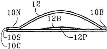
FIG. 1A is a plan view of bubble device 10 showing
dispersing bubble 12 and product 12P within sealed
perimeter 1 P for dispersion into zone of concern IOZ;
FIG. 1B is a sectional view of the bubble device and
dispersing bubble of FIG. 1.A showing opposed webs 1 S and
1QC with breaching seal 10B and non-breaching seal 10N;
FIG. 1C is a sectional view of the bubble device and
dispersing bubble of F'IG. 1A showing transport fluid 12F
within the dispersion bubble in a compressed state under
external pressure;
FIG. 1D is a sectional view of the bubble device and
dispersing bubble of FIG. 1A showing edge breach 12E
along the breaching seal and the transport fluid escaping
into the zone of concern;
FIG. 1E is a side view of the bubble device and
dispersing bubble of FIG. 1A showing the opposed webs 10S
and 10C completely separated and residue product 12R
exposed;
FIG. 2 is a plan view of an array 24A with a
plurality of bubble devices 22 showing perforated lines
24L for separation;
CA 02656219 2008-12-23
WO 2008/000658 PCT/EP2007/056082
FIG. 3 is a plan view of a strip 34S with a
plurality of bubble devices 32 showing selected products
301 to 30V;
5 FIG. 4 is a side view of a roll 44R of bubble
devices 42 mounted on dispenser 44D;
FIG. 5 is a side view of bubble device 50 showing
convex support web SOS and convex cover web 50C;
FIG. 6 is a side view of bubble device 60 with
dispersion bubble 62 showing wrap member 66W with discard
pocket 66P for disposing the breached bubble after
dispersion;
FIG. 7A is a side view of bubble device 70 with
dispersion bubble 72 tilted upward showing product 72P in
the lower rear region of the bubble next to non-breaching
seal 70N;
FIG. 7B is a side view of the bubble device of FIG.
7A showing dispersion bubble 72 tilted downward with
product 72P in the lower forward region of the bubble
next to breaching seal 70B; and
FIG. 8 is a flow chart showing the basic steps and
sub-steps in the method of dispersion.
The first digit of each reference numeral in the above
figures indicates the figure in which an element or
feature is most prominently shown. The second digit
indicates related elements or features, and a final
letter (when used) indicates a sub-portion of an element
or feature.
CA 02656219 2008-12-23
WO 2008/000658 PCT/EP2007/056082
6
REFERENCE NUMERALS IN DRAWINGS
The table below lists the reference numerals
employed in the figures, and identifies the element
designated by each numeral.
10 Bubble Device 10
10B Breaching Seal lOB
lOC Cover Web 10C
1ON Non-breaching Seal 10N
1OP Sealed Perimeter lOP
loS Support Web 10S
1OZ Zone of Concern 1OZ
12 Dispersing Bubble 12
12B Product Surface Boundary 12B
12C Peel Tab 12C
12E Edge Breach 12E
12F Compressible Transport Fluid 12F
12P Product 12P
12R Product Residue 12R
12S Peel Tab 12S
22 Plurality of Bubble Devices 22
24A Array 24A
24L Perforated Lines 24L
30B Breaching Seal 30B
301 Selected Product 301
3011 Selected Product 3011
30IIISelected Product 30111
30IV Selected Product 30IV
30V Selected Product 30V
32 Plurality of Bubble Devices 32
34S Strip 34S
42 Dispersing Bubble 42
44A Axis 44A
44D Dispenser 44D
44R Roll 44R
50 Bubble Device 50
50C Convex Cover Web 50C
50S Convex Support Web 50S
52C Convex Bubble 52C
52S Convex Bubble 52S
66 Bubble Device 60
60S Support Web 60S
62 Dispersion Bubble 62
66W Wrap Member 66W
66P Discard Pocket 66P
70 Bubble Device 70
70B Breaching Seal 70B
70N Non-breaching Seal 70N
72 Dispersion Bubble 72
72P Product 72P
76S Product Swab 76S
CA 02656219 2008-12-23
WO 2008/000658 PCT/EP2007/056082
7
GENERAL EMBODIMENT - (FIG.s 1 ABCDE)
Bubble device 10 permits a user to directionally
disperse a product under compressive pressure toward zone
of concern 1OZ. Opposed webs 103 and 7.OC of enclosure
material are pressed together to form sealed perimeter
10P around a central enclosure. The central enclosure
forms dispersing bubble 12 enclosed between the opposed
webs within the perimeter. The opposed webs may have
multiple layers to provide properties such as
waterproofing, UV protection, increased bulk, and
strength. The opposed webs may be any suitable enclosing
material such as plastic, paper fabric, cellophane, or
biodegradable matter. Thin mylar plastic forms a flexible
film with hermetic properties, and may be employed as a
bubble material. The perimeter has a breaching seal 10B
for product dispersion and a non-breaching seal lON along
the remaining perimeter. The breaching seal of the bubble
device may be a frangible web union and the non-breaching
seal may be a destructive web union. The frangible
breaching seal may be formed at a lower web-to-web
pressure and at a lower temperature for a shorter time
than the destructive non-breaching seal. The frangible
seal breaches at a lower pressure and requires less
compressive energy. The breaching seal may be narrower
than the non-breachingseal (as shown in FIG.s 1A, and
1B). The narrow breaching seal requires less bubble
enlargement to force an edge breach.
Product 1OP for dispersion and compressible product
transport fluid 12F are contained within the dispersing
bubble. The transport fluid may be any compressible
medium such as a chemically pure gas or nitrogen gas or
other inert gas (or combination of gases) or ambient air
or other suitable fluid. The transport fluid is
compressed under external pressure applied by the user,
CA 02656219 2008-12-23
WO 2008/000658 PCT/EP2007/056082
8
for causing the opposed webs to separate and the bubble
to enlarge along the breaching seal. The user provides
the external pressure manually by pressing on the
dispersing bubble between the user's thumb and
forefinger. In other embodiments, mechanical devices may
be employed to create the compression. As the transport
fluid is compressed, energy of compression builds and is
stored within the dispersing bubble. The compression
causes the bubble to bulge toward the frangible breaching
seal (see FIG. 1C). The web separation occurs inside the
dispersing bubble, forcing an edge breach 12E in the
breaching seal from the inside to the outside. The
compressed transport fluid rapidly escapes as a released
blast through the edge breach, and expands as it passes
out of the dispersing bubble. The stored energy of
compression within the bubble is released as kinetic
energy of the escaping transport fluid.
The escaping expanding transport fluid transports at
least a portion of the product out of the bubble for
dispersion toward zone of concern 10Z adjacent to the
dispersing bubble. The zone may be an area of skin
enhanced by a perfume product or being treated by a
beneficial substance such as an ointment or medication.
The zone may be a medical machine or a portion of a
working surface or a surgical instrument, being
sterilized by an antiseptic vapor without contact.
The bubble device has opposed peel tabs 12S and 12C
formed by the enclosure material of the opposed webs
proximate the edge breach as the bubble breaches. The
tabs may be peeled apart by the user to further separate
the opposed webs and gain access to product residue
remaining in the bubble after the escape of the fluid.
The opposed webs 10S and 10C may be completely separated
CA 02656219 2008-12-23
WO 2008/000658 PCT/EP2007/056082
9
forming application pads (see FIG. 1E) for applying any
product residue 12R remaining on the webs after the
dispersion.
PRODUCT 12P - (FIG.s 1ABCDE)
The product contained within the dispersing bubble
may be a liquid or a gas or a powder, or a combination
thereof. A portion of the product becomes mingled with
the transport fluid and is transported through the edge
breach with the rapidly escaping transport fluid. The
mingled product is carried by the transport fluid in
solution, as a mixture, or as a suspension of minute
airborne particles. The product may be a finely divided
powder such as graphite lubricant or confectioner's sugar
or fingerprint toning powder, which is temporarily
airborne just after the dispersion. The dust-like powder
quickly settles onto the zone of concern. The graphite
powder settles as film of lubricant, and the
confectioner's sugar settles as a decorative sweet
frosting, and the fingerprint powder tones the oil
patterns. The presence of the mingled product may be
enhanced by shaking the device just prior to dispersion.
The product contained within the dispersing bubble
has surface boundary 12B exposed to the transport fluid.
A portion of the liquid product maybe atomized into the
transport fluid during the dispersion by the rapid flow
of the of the transport fluid across the surface. The
velocity of the transport fluid creates a low pressure
above the liquid product which pulls the product atoms
and/or molecules across the surface boundary into the
flow. This atomized product is transported through the
edge breach with the escaping transport fluid.
CA 02656219 2008-12-23
WO 2008/000658 PCT/EP2007/056082
A portion of the liquid product is vaporized into
the transport fluid reaching a vapor pressure
equilibrium. A slight additional portion vaporizes across
the surface boundary as the transport fluid warms due to
5 compression within the dispersing bubble. A corresponding
slight portion of vapor condenses out of the transport
fluid as the transport fluid cools due to expansion
outside the dispersing bubble. A mist of condensation
settles onto the zone of concern and gives the user
10 feedback as to the direction of the dispersion. A portion
of the liquid product contained within the dispersing
bubble may be transported through the edge breach as
small blast droplets of product by the rapidly escaping
transport fluid. These droplets soon fall out of the
escaping flow onto the zone.
A portion of the liquid product contained within the
dispersing bubble may remain as surface residue 12R on
the enclosure material of the breached dispersing bubble
after the product dispersion. Alternatively, the liquid
product may be completely mingled into the transport
fluid leaving no residue on the opposed webs after
dispersion.
In a fluid embodiment, the product may be a gas
which is completely mixed with the transport fluid. The
gas product may function as its own compressible
transport fluid, in which case the entire content of the
dispersing bubble is the gas product. In this fluid
embodiment, there is no liquid or powder or residue
remaining on the web material.
CA 02656219 2008-12-23
WO 2008/000658 PCT/EP2007/056082
11
PORTABLE EMBODIMENTS
Liquid products such as perfumes, sun-screen lotion,
deodorants, insect repellant etc., may be packaged in a
bubble pack carried in a handbag for immediate use. The
bubble may be a light, compact unit suitable containing a
single application of the product weighing a fraction of
a gram. A single ounce of upscale perfume may be costly,
and typically comes in a thick, heavy glass vial,
difficult to transport in a handbag. The small bubble
pack may be employed for samples distributed from retail
counters, and for small amounts of products typically
found in hotel bathrooms. A smaller household version may
be available to consumers at the super-market or in
drugstores.
Pandemic Embodiment
The liquid product within the bubble may be a
disinfectant for viral, bacterial, and other airborne or
contact pathogens in pandemic situations. First response
personnel may carry a supply of disinfectant bubbles
along with protective latex gloves. A large carton
containing thousands of light, cheap disinfectant
bubbles, weighing only a few pounds, could easily be
distributed to the public from emergency stations.
PRODUCT SWAB 76S - (FIG. 7B)
Product swab 76S of enclosure material may be
provided proximate the edge breach for transferring
product to zone of concern by physical contact. The
product swab may be an extension of the lower web for
catching the blast droplets and condensate after they
have been transported through the edge breach and falien-
out of the escaping flow. The extended lower lip may be
concave in shape for retaining the fallen-out product.
CA 02656219 2008-12-23
WO 2008/000658 PCT/EP2007/056082
12
PRESENTATION - (FIG.s 2, 3, and 4)
Bubble devices each with a dispersing bubble, may be
presented in array 24A formed by opposed web sheets to
provide a plurality of dispersing bubble 22 on single
support. Lines of perforations 24L define a four-sided
separation grid between the bubble devices, permitting
the devices to be individually removed from the array.
The user may tear off one or more devices, or remove an
entire strip (see FIG. 3), along the perforations.
Dispersing bubbles 32 in linear strip 34S may
contain a selection of products 301, 3011, 30II1, 301V
and 30V for dispersion. The selection of products may be
dispersed into the zone of concern in a specified
protocol or time sequence. For example, medical
procedures may involve several antiseptic and preparatory
actions executed in a prescribed order. A strip may be
provided with multiple dispersing bubbles, each holding
whatever substance is required for each action. A blood
donor typically gets a liberal alcohol wash around the IV
insertion area, and then a local iodine rub. Alcohol and
iodine may be provided at the donor station in a
convenient disposable two bubble strip. A supply of
strips for similar consumer protocols may be carried in
the consumers purse or pack. Breaching seal 30H on each
dispersing bubble may be along the same edge of the strip
defining a common dispersion direction for all of the
bubbles in the strip.
Alternatively, a bubble device may present
dispersing bubbles 42 from a suitable dispensing
structure 44D employing a roll 44R. The roll unwinds
around axis 44A as the user tears off each individual
dispersing bubble.
CA 02656219 2008-12-23
WO 2008/000658 PCT/EP2007/056082
13
SUPPORT/COVER WEBS - (FIG. 5)
One of the opposed webs forming the dispersing
bubbles may be support web 50S and the other opposed web
may be cover web 50C. Both the support web and the cover
web may be convex forming support convex portion 52S of
the bubble and cover convex portion 52C, defining a
double convex dispersing bubble as shown in FIG 5.
Alternatively, the support web may be flat and the cover
web may be convex defining a stable dispersing bubble
(see FIG. 7AB). During manufacturing, the web material
may be pulled into the convex shape by a vacuum. The
convex shape retains the product in position until the
opposed web is pressed into place.
WRAP POCKET - (FIG. 6)
The remnants of the breached bubble coated with the
residue of the product, may be folded up and discarded
directly. Alternatively, the bubble may have an attached
cloak or shroud, which may be used to wrap the breached
bubble. A wrap member extending from at least one of the
opposed webs may be employed for wrapping the breached
dispersing bubble after dispersion of the product. In the
embodiment of FIG.6, wrap member 66W is formed on support
web 60B of bubble device 60, and provides discard pocket
66P for receiving the breached dispersing bubble. The
used bubble device may be rolled and tucked into the
pocket for disposal. The encased bubble remnant may be
temporarily stored in a handbag for disposal later. The
wrapped storage permits a second and possible third
application of the product.
CA 02656219 2008-12-23
WO 2008/000658 PCT/EP2007/056082
14
METHOD OF DISPERSING (FIG. 8)
The basic steps of the general method for
directionally dispersing a product toward a zone of
concern under compressive pressure by a user are shown in
the flow chart of FIG. 8, and described below, and in
Fig.s IABCDE above.
Directing a bubble device toward the zone of
concern. The bubble device is formed by opposed webs of
enclosure material pressed together to form a sealed
perimeter around a central enclosure. The perimeter has a
breaching seal for product dispersion, and a non-
breaching seal along the remaining perimeter. The central
enclosure forms a dispersing bubble enclosed between the
opposed webs within the perimeter. The dispersing bubble
contains a product for dispersion and a compressible
product transport fluid.
Compressing the transport fluid within the
dispersing bubble by external pressure form the user (see
FIG. 1C) .
Expanding the dispersing bubble along the breaching
seal inside the dispersing bubble under the external
pressure on the transport fluid (see FIG. 1C).
Separating the opposed webs along the breaching seal
(see FIG. 1D).
Forcing an edge breach in the breaching seal from
inside to outside due to the separation of the opposed
webs (see FIG. 1D).
CA 02656219 2008-12-23
WO 2008/000658 PCT/EP2007/056082
Permitting the compressed transport fluid to ratpidly
escape as a released blast through the edge breach, and
expand out of the bubble (see FIG. 1D).
5 Transporting at least a portion of the product out
of the bubble with the escaping transport fluid for
dispersions toward the zone of concern (see FIG. 1D).
The above general method may have the following
10 additional sub-steps.
Shaking the product and the transport fluid within
the dispersing bubble before the directing step to
enhance the presence of the product mingled in the
15 transport fluid.
Directing the bubble device upwards during the
directing step causing the product within the dispersing
bubble to shift downwards and backwards away from
breaching seal (see FIG. 7A). The absence of liquid
product near the breaching seal insures the dispersion
into the zone of concern will be mostly vapor, and
include less liquid.
Directing the bubble device downwards during the
directing step causing the product within the dispersing
bubble to shift downwards and forwards closer to the
breaching seal (see FIG. 7B). The existence of liquid
product near the breaching seal insures the dispersion
will include almost all of the liquid product along with
the vapor.
Further separating the opposed webs after the
dispersion step by means of opposed peel tabs formed on
the opposed webs proximate the edge breach (see FIG. lE).
CA 02656219 2008-12-23
WO 2008/000658 PCT/EP2007/056082
16
The above method has many variations and
applications. For example, in a perfume dispersion
scenario, the consumer has four procedure options:
Light Scent
Limited scent may be obtained from the initial cloud
of carburetted mist plus the single molecules of perfume
dissolved (evaporated) into the transport fluid.
Medium Scent
More scent may be obtained by agitating the bubble
lightly through tapping or shaking before breaching, to
include liquid product temporarily suspended in the
transport fluid due to the agitation.
More Scent
Even more scent may be obtained by tilting the
bubble downward to include more liquid product in the
transport fluid.
Maximum Scent
The most scent may be obtained by heavy agitation to
maximize the amount of suspended liquid. Then using the
product remaining as a coating on the inside surface of
the bubble.
CA 02656219 2008-12-23
WO 2008/000658 PCT/EP2007/056082
17
INDUSTRIAL APPLICABILITY
It will be apparent to those skilled in the art that
the objects of this invention have been achieved as
described hereinbefore by providing a bubble device for
dispersing a product from a dispersing bubble into a zone
of concern. The force of compression forces an edge
breach in the bubble. The compressed transport fluid and
product escape through the edge breach ina release of
compressed transport fluid. The energy for compressing
the transport fluid the product is supplied by the user.
The product is dispersed without physical contact with
the zone of concern. The product is propelled out of the
dispersing bubble in a vapor state by the compressive
energy within the bubble. The bubble device has opposed
peel tabs permitting the user to open the dispersing
bubble for access to the product. Product residue
remaining within the bubble is applied to the zone of
concern by contact application. The bubble device may be
conveniently discarded after dispersion in a wrap pocket.
The bubble device may have a plurality of dispersion
bubbles with a selection of products for use in sequence.
An additional portion of product vaporizes as the
transport fluid warms due to compression, and condenses
as the transport fluid cools due to expansion outside the
dispersing bubble.
Various changes may be made in the structure and
embodiments shown herein without departing from the
concept of the invention. Further, features of
embodiments shown in various figures may be employed in
combination with embodiments shown in other figures.
Therefore, the scope of the invention is to be
determined by the terminology of the following claims and
the legal equivalents thereof.