Note: Descriptions are shown in the official language in which they were submitted.
CA 02656251 2008-12-04
WO 2007/140603 PCT/CA2007/000998
PROCESS AND APPARATUS FOR FORMING
A MINIMAL HEADSPACE POUCH
BACKGROUND OF THE INVENTION
FIELD OF THE INVENTION
In one of its aspects, the present invention provides a process for forming a
minimal headspace pouch containing a flowable material. In another of its
aspects, the
present invention provides an apparatus for forming a minimal headspace pouch
containing a flowable material. In yet another of its aspects, the present
invention
provides a minimal headspace pouch formed by the process of the present
invention.
DESCRIPTION OF THE PRIOR ART
Flexible Liquid Packaging is used to package many consumer goods,
particularly food and beverages, which are often packaged in pouches formed of
flexible materials. (The term "Liquid Packaging" is understood by those of
skill in the
art to refer to both liquids and other flowable materials, as explained
further below.)
Many products packaged in pouches are particularly sensitive to oxygen
degradation.
Many products particularly in the food industry require minimal air exposure
to
protect their flavour, colour, nutritive value, texture and shelf life. Oxygen
reacts
readily with many components of these products forming so-called "off-
flavours" and
"off-colours". Removal of oxygen from the packaging process of many foods
allows
for extended shelf life with no loss of flavour. In the case of film pouches,
as a
byproduct of certain preferred forming techniques, oxygen is commonly trapped
in a
headspace that is created above the product upon pouch formation.
Besides the advantages associated with minimizing oxygen exposure, for
certain applications, minimal headspace is required to facilitate pouch
insertion into a
secondary container; a common packaging arrangement involves inserting a pouch
in
a cardboard box (the "bag-in-box" principle). A slack pouch is easier to
insert into a
box and will better form to shape than a puffy pouch (i.e. one with a large
air-filled
headspace).
Fill reliability or control is important in packaging. In fact, headspace is a
common associated effect of techniques used to ensure fill reliability. In
many
1
CA 02656251 2013-11-12
WO 2007/140603
PCT/CA2007/000998
jurisdictions, the advertised product quantity is mandated to be a minimum
product
quantity. Poor fill accuracy therefore requires that the fill level be set at
above the
posted product quantity, thereby raising costs. Consequently, while limiting
headspace is important, it is also important to have reliable fill control.
One known
method for minimizing headspace involves filling a tube for making a pouch
above
the level of the top of the pouch and sealing through the product. This method
can
suffer from poor fill control. In addition, the product can interfere with
seal formation.
Pouches made on vertical form-fill-seal machines are widely used in the
Liquid Packaging industry. A typical vertical form-fill-seal machine includes
a roll
unwind, a forming section where film folds itself vertically, a vertical
sealing section
and a horizontal sealing section (sealing at the same time the top of a filled
pouch and
the bottom seal of the next pouch) and a chute and/or discharge conveyor
system. At
both the vertical and horizontal sealing sections, heat sealing jaws are
generally
employed to seal the film. Product is supplied through a supply conduit,
generally a
fill tube, delivering product in the continuous film tube created by the
vertical sealing
jaws. The vertical form-fill-seal method allows the efficient and effective
packaging
of foods and other products. Minimizing headspace in pouches made by this
method
would minimize oxygen degradation, and facilitate use of pouches made by this
method in applications that require minimal headspace.
United States patent 5,038,550 to Wirsig et al. teaches a process and
apparatus for improving vertical form-fill-seal machines, by minimizing the
formation
of tucks in the horizontal seals of pouches made on a vertical form-fill-seal
machine.
Minimizing tucking must be a consideration in any modification to a vertical
form-
fill-seal machine. In one embodiment, the invention includes a pair of
transverse heat
sealing jaws; a pair of spreader fingers adapted to be inside the tubular film
and to
shape the tubular film; and one or two pairs of detucker fingers adapted to
act in
unison with the transverse motion of the heat sealing jaws, to pinch a
longitudinal
edge of the tubular film and to urge the pinched tubular film transversely in
a
direction substantially parallel to the closing surfaces of the jaws and away
from the
other longitudinal edge of the tubular film.
2
CA 02656251 2008-12-04
WO 2007/140603 PCT/CA2007/000998
Generally in operation the continuous film tube of vertical form-fill-seal
machines is supplied with product from a product delivery system with
continuous or
intermittent flow through the supply conduit.
The delivery system may include a balance tank equipped with level
control (float, ultrasonic, capacitance, etc.) and a supply conduit with a
poppet valve
for regulating flow. The machine may also include components for maintaining a
constant level of product inside the continuous film tube. Typically, these
components
include a sensor for determining the level of the product inside the
continuous film
tube and a control device for controlling the poppet valve regulating the flow
of
product into the continuous film tube.
Known level sensors include a magnetic float housed inside the
continuous film tube, the position of which can be determined by sensors
positioned
inside or outside the continuous film tube.
Other known sensors exploit the electrical conductivity of the product to
create a circuit, whereby the values of electric quantities in the circuit,
such as current
flow, depend on the level of the product inside the continuous film tube.
United States patent 4,675,660 to Boscolo teaches a level sensor that
involves creating energy waves inside a supply conduit using a transducer
housed
inside a packaging tube and contacting the conduit. The energy waves are
transmitted
to the product inside the packaging tube, which can then be detected and
converted so
as to indicate the level of the food product.
European patent 681 961 teaches a level sensor that includes a device for
detecting temperature located outside a continuous packaging tube and
comprising a
number of temperature sensors located successively along the tube. The food
product
level inside the tube is determined based on the relationship between
temperature
sensors detecting a surface temperature of the tube affected by the food
product, and
temperature sensors detecting a surface temperature not affected by the food
product.
United States patent 6,684,609 to Bassissi et al. teaches a vertical form-
fill-seal machine that has a capacitive level sensor. The capacitive level
sensor is
positioned outside the continuous film tube facing an end portion of the fill
conduit.
3
CA 02656251 2008-12-04
WO 2007/140603
PCT/CA2007/000998
The sensor and the fill conduit define a capacitive element, whose capacitance
depends at least in part on the amount of food product therebetween.
Various methods for reducing headspace in packages are known.
= United States patent 6,543,206 to Seward et al. teaches an apparatus and
method for evacuating and sealing a pre-formed bag made of a sealable material
and
containing a comminuted product. The bag is positioned with its open upper end
around a sleeve through which a hollow probe can be extended. A pair of jaw
members close to form an outer temporary seal above an intermediate region of
the
bag above the level of the surface of the product in the bag where a permanent
seal is
to be formed. A pair of lower jaw members close to form an inner temporary
seal
about a lower region of the bag above the surface of the product. With the
probe
extended through the sleeve into the bag, the bag is evacuated through the
probe.
After evacuation is completed and the probe is withdrawn, a pair of sealing
members
close against the intermediate region of the bag in order to form a permanent
seal for
the bag.
Similarly, published United States patent application 2002/0023410 to
Seaward et al. teaches an apparatus and method for sealing a pre-formed bag
made of
a sealable material and containing a flowable product. The bag is positioned
with its
open upper end around a sleeve through which a hollow probe can be extended. A
pair of upper jaw members close to form an outer temporary seal about an upper
region of the bag above the level of the surface of the product in the bag. A
pair of
lower jaw members close to form an inner temporary seal about a lower region
of the
bag below the upper and intermediate regions and above the surface of the
product.
The hollow probe is used to evacuate the bag, and after evacuation is
completed and
the probe is withdrawn, a pair of sealing members close against the
intermediate
region of the bag to form a permanent seal. The method further teaches
bleeding back
a small amount of a desirable material, which may be an inert gas.
European patent application 381 400 teaches a form-fill-seal machine
having a constraint chute below the heat sealing jaws of the machine. The
constraint
chute includes two vertical walls, one of the walls being adapted to move away
from
the other wall under tension and to return to its original position, the
degree of tension
4
CA 02656251 2008-12-04
WO 2007/140603 PCT/CA2007/000998
and the friction of the walls is sufficient to squeeze the pouch, while
permitting the
pouch to travel therebetween. The plane of both of the walls is perpendicular
to the
direction of the closing jaws. This patent teaches sealing the tubular film
below the
material/air interface when pouches are completely filled (no "headspace").
United States patent 4,964,259 to Ylvisaker et al. teaches a method of
deflating a package of solid goods prior to the time the fill opening is
sealed that
includes a blast of air against the exterior flexible sidewalls of the package
to thereby
drive gas from the inside of the package. The blast of air impinges above the
upper
level of the goods and ceases upon the engagement of the sealing jaws.
United States patent 5,231,817 to Sadler teaches a vertical form-fill-seal
machine for making material-filled, slack pouches filled with flowable
material,
having little or no headspace in the pouches. One jaw of the heat sealing
assembly has
a jaw wall convex about a vertical axis and located below the heat sealing
element.
The opposite jaw of the assembly has a jaw wall of an elastomeric sheet
stretched
under tension and adapted to cooperate with the convex jaw wall. During
operation,
the jaw walls bias against the material-filled pouch causing air to be
expelled from the
material and collapsing the tube as the jaws are closed. While this system
represents
an improvement in the art, there remains a need for a process and apparatus
for
forming minimal headspace pouches via the vertical form-fill-seal method.
It is an object of the present invention to obviate or mitigate at least
one of the above-mentioned disadvantages of the prior art.
5
CA 02656251 2008-12-04
WO 2007/140603 PCT/CA2007/000998
SUMMARY OF THE INVENTION
Accordingly, in one aspect, the present invention provides a process for
forming a pouch having an evacuated headspace containing a flowable material.
The
process comprises the steps of: providing a continuous tube of flexible and
sealable
film; supplying the continuous tube with a predetermined amount of flowable
material; pinching the continuous tube above a sealing region so as to form a
pinched
portion of the continuous tube; evacuating the headspace between the pinched
portion
and the predetermined amount of flowable material; and sealing the continuous
tube
at the sealing region to form a top seal of a previously formed pouch
containing
flowable material and a bottom seal of a next-to-be filled pouch.
In another aspect, the present invention provides a pouch formed by the
process of the invention. In yet another aspect, the present invention
provides a
package, which comprises a pouch of the present invention inside a secondary
container.
In yet another aspect, the present invention provides a vertical form-fill-
seal apparatus for forming a pouch containing a flowable material and having
an
evacuated headspace. The apparatus comprises: a tube forming section for
forming a
vertical continuous tube from a roll of film; a horizontal sealing section for
forming a
transverse seal across the vertical continuous tube; a filling station for
supplying a
predetermined amount of flowable material to the vertical continuous tube;
pinchers
for transversely pinching the vertical continuous tube to form a pinched
portion of the
continuous tube; an evacuating passage between the pinchers that opens onto
the
headspace between the predetermined amount of flowable material and the
pinched
portion; and a deflating apparatus for evacuating the headspace via the
evacuating
passage.
BRIEF DESCRIPTION OF THE DRAWINGS
Embodiments of the present invention will be described with reference to
the accompanying drawings, wherein like reference numerals denote like parts,
and in
which:
6
CA 02656251 2008-12-04
WO 2007/140603
PCT/CA2007/000998
Figure 1 illustrates a schematic view of an apparatus of the present
invention.
Figure 2 illustrates a partial front schematic view of an embodiment of the
apparatus with closed pinchers and a partially formed pouch of the present
invention.
Figure 3 illustrates a partial front schematic view of an embodiment of the
apparatus with activated deflators and a partially formed pouch of the present
invention.
Figure 4 illustrates a partial front schematic view of an embodiment of the
apparatus with the deflators released and a partially formed pouch of the
present
invention.
Figure 5 illustrates a partial front schematic view of an embodiment of the
apparatus with the sealing and cutting jaws activated and a partially formed
pouch of
the present invention.
Figure 6 illustrates a partial front schematic view of an embodiment of the
apparatus wherein the sealing jaws, pinchers and deflators are open.
Figure 7 illustrates a partial perspective view of an embodiment of the
apparatus of the present invention, with the pinchers in a closed position. .
Figure 8 illustrates a magnified partial perspective view of the pinchers of
Figure 7.
Figure 9 a front schematic view of an embodiment of the present
apparatus, wherein the evacuating passage is formed by an internal vertical
seal.
Figure 10 illustrates illustrates a front schematic view of a pouch suitably
formed by the embodiment of the apparatus shown in Figure 9.
Figure 11 illustrates a front schematic view of a pouch suitably formed by
the embodiment of the apparatus shown in Figure 9.
Figure 12 illustrates a partial front schematic view of an embodiment of
the apparatus of the present invention comprising U-shaped pinchers.
7
CA 02656251 2008-12-04
WO 2007/140603
PCT/CA2007/000998
Figure 13 illustrates a partial schematic perspective view of an
embodiment of the apparatus and partly formed pouch of the present invention.
Figure 14 illustrates a partial schematic perspective view of a further
embodiment of the apparatus and partly formed pouch of the present invention,
wherein the evacuating tube has a hooked portion.
DETAILED DESCRIPTION OF THE PREFERRED EMBODIMENTS
As explained above, the process of the present invention involves forming
a continuous film tube into sealed pouches. Typically, the steps of forming
the
continuous film tube, forming a first seal in the continuous film tube,
filling the
continuous tube with product, and forming a second seal above the product,
thereby
yielding a closed filled pouch, will be performed on a single machine of the
vertical
form-fill-seal type. The continuous film tube is formed of a flexible film, of
the type
known by those of skill in the art.
While the volumes of pouches according to the present invention are not
particularly restricted, suitable pouch volume ranges are from about 1 litre
to 12 litres,
and more suitably 3 litres to 5 litres. The volume of product contained in the
pouch
will depend on the volume of the pouch. Where the terms "minimal headspace" or
"evacuated headspace" are used in this application, it will be understood that
these are
relative to standard pouches formed by the standard form-fill-seal process.
Preferably,
the headspace of pouches of the present invention is reduced by the process of
the
present invention to a volume of 4 percent or less by volume of the pouch.
Materials suitable for forming the pouch of the present invention are well
known to those of skill in the art. Generally the pouch should be sealable and
have
suitable properties (i.e. strength, flexibility) for carrying the desired
product therein.
The pouch of the present invention comprises any suitable plastic film
material, such as linear low-density polyethylene, for example. The pouch may
comprise multiple plies. An outer ply may be a barrier lamination including a
layer
made from a foil material or a suitable metallized substrate, or any other
recognized
flexible barrier or substrate materials including non-metallized materials. An
outer
barrier lamination suitably comprises an outer layer of Nylon, an intermediate
layer or
foil, and an inner layer of polyethylene. Alternatively, the barrier
lamination could
8
CA 02656251 2008-12-04
WO 2007/140603
PCT/CA2007/000998
comprise an outer layer of polyethylene, an intermediate layer of metallized
Nylon, or
metallized polyester, or metallized polyvinyl alcohol, and an inner layer of
polyethylene.
Other alternate intermediate layers having suitable barrier characteristics
include unmetalized polyvinyl alcohol, unmetalized ethyl vinyl alcohol, and
metalized
ethyl vinyl alcohol.
In any event, all of the materials are selected such that they can be sealed
together, giving due consideration to the product to be packaged. Preferably,
the lines
of seals extend through the entire side walls, including all plies thereof, to
form a
secure pouch seal.
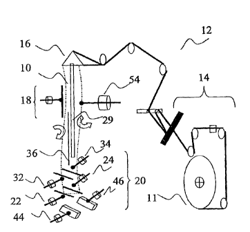
Turning to Figure 1, there is shown a continuous film tube 10 formed
from a roll of film 11 using a vertical form-fill-seal machine 12 that
includes a roll
unwind 14; a forming section 16 where the film folds itself vertically; and a
vertical
sealing section 18 where the longitudinal edges of the film are sealed
together to form
a vertical seal, typically a "lap seal" or a "fin seal" (although the type of
vertical seal is
not particularly restricted and is within the purview of a person skilled in
the art.)
Suitable vertical sealing jaws could be thermic (constantly heated jaw) or
impulse
(intermittently powered for each seal). The form-fill-seal machine 12 further
includes
a horizontal sealing section 20, where a transverse heat seal is made.
Typically the
transverse heat seal will be formed by a pair of sealing jaws 22,24, although
as will be
understood by a person skilled in the art, other sealing arrangements may be
possible,
although for the purposes of this description, horizontal sealing will be
described in
terms of sealing jaws 22,24. Typically, the sealing jaws 22,24 are also
associated with
a cutting apparatus (not shown) for severing a formed and filled pouch from
the next
pouch. The machine 12 may include spreader fingers 26,28 (see e.g. Figures 7,
8, 13
and 14) adapted to be inside the continuous film tube 10 and to shape the
tubular film
thereof towards a layflat configuration, such layflat configuration having
longitudinal
edges, thus spreading the longitudinal edges of the continuous film tube 10
outwardly.
9
CA 02656251 2008-12-04
WO 2007/140603 PCT/CA2007/000998
The apparatus of the present invention further comprises a filling station
typically comprising a product balance tank (not shown) and a supply conduit
29
above horizontal sealing section 20.
After making the horizontal seal, but before the sealing jaws 22,24 are
opened, a quantity of product is supplied to the continuous film tube 10 via
the supply
conduit 29, which fills the continuous film tube 10 upwardly from the
transverse seal.
The continuous film tube 10 is then caused to move downwardly a predetermined
distance. This movement may be under the influence of the weight of the
material in
the continuous film tube 10, or may be caused by pulling or mechanically
driving the
continuous film tube 10. The sealing jaws 22,24 are closed again, thus
collapsing the
continuous film tube 10 at a second position, usually just above the
air/product
interface. The sealing jaws 22,24 typically seal and sever the continuous film
tube 10,
or the tube may be severed subsequently. Suitably, a pouch may be
simultaneously
heat sealed and severed from a subsequent pouch. Alternatively, the pouch may
be
sealed and subsequently cut from the subsequent pouch, such as by a knife.
Another
example for severing pouches formed in this manner could be through the use of
a
perforated or weakened tear line, which can be produced in any number of known
ways. Suitable methods for separating pouches are known to those of skill in
the art.
Product suitable for the pouch of the present invention are flowable
materials. The term "flowable material" does not include gases, but includes
materials
which are flowable under gravity, may be pumped or otherwise transported
through
tubes. Such materials include emulsions, e.g. ice cream mix; soft margarine;
food
dressings; pastes, etc. meat pastes; peanut butter; preserves, e.g. jams, pie
fillings,
marmalade, jellies; dough; ground meat, e.g. sausage meat; powders, e.g.
gelatine
powders; detergents; liquids, e.g. milk, oils; granular solids, e.g. rice,
sugar; and
mixtures of liquids and solids, e.g. chunky soup, cole slaw, macaroni salad,
fruit
salad, sliced pickles, cherry pie filling. In one application, the flowable
material is a
liquid suitable for consumption, for example fruit juice, milk, and wine.
Each pouch formed will contain a predetermined amount of product 30.
Supplying each pouch with a predetermined amount of product 30 (shown in
Figures
2 through 6) can be achieved by accurately metering-in product by methods
known in
the art for either continuous fill or intermittent fill operations. Suitable
methods of
CA 02656251 2008-12-04
WO 2007/140603
PCT/CA2007/000998
metering-in, for example, may employ constant (continuous) flow of product and
an
accurate sealing sequencing timer or any known dosing method enabling
intermittent
filling of the product.
With the predetermined amount of product 30 metered-in to the
continuous film tube 10, a set of pinchers 32,34 are closed to ensure product
30 stays
inside the continuous film tube 10. In a continuous filling operation, the
pinchers
32,34 also separate product from the next pouch being produced as product
constantly
pours in. An evacuating passage (described in more detail below) permits
evacuation
of the headspace through the closed pinchers 32,34, while preventing flow of
product
from one pouch to the next. "Passage" refers to a path or route through which
air can
pass to evacuate the headspace between the pinchers.
In one embodiment shown in Figures 7 and 8, the pinchers 32,34 are
closed against an evacuating tube 36, which acts as the evacuating passage.
The
pinchers 32,34 can have a sealing material, such as a rubber ribbon for
pinching about
the evacuating tube 36. Securely pinching about the evacuating tube 36 so as
to
minimize product leaks promotes fill accuracy.
Referring to Figures 7 and 8, in the embodiment shown, the evacuating
tube 36 passes between the pinchers 32,34 so that its head 37 opens on to the
headspace between supplied predetermined amount of product 30 and the pinchers
32,34. In the vertical form-fill-seal machine 12, the head 37 of evacuating
tube 36
may sit at a lower elevation than the pinchers 32,34, or between pinchers
32,34
opening on to the headspace. While the term, "head" 37 is used, it will be
apparent to
a person skilled in the art that the evacuating tube 36 may have a consistent
profile
along the length thereof. While the shape of the evacuating tube head 37, and
the
corresponding receiving portion of the pinchers 32,34 is not particularly
restricted, a
preferred shape limits tucking and tearing. A preferred shape for the head 37
has been
found to be a diamond, as shown in Figure 8.
In another embodiment of the evacuating passage, the pinchers 32,34
extend across the width of the continuous film tube 10, but are closed with a
force
which allows evacuation through the closed faces of the pinchers 32,34, while
limiting product flow. The shape of the faces of the pinchers can facilitate
the
11
CA 02656251 2008-12-04
WO 2007/140603
PCT/CA2007/000998
formation of this type of evacuating passage. The front faces of the pinchers,
for
example, may suitably have textured or ribbed rubber faces that facilitate the
passage
of air from the headspace therebetween. While the term evacuating "passage" is
used,
a person skilled in the art will understand that the invention may include a
plurality of
small passages through which, collectively, the headspace is evacuated.
In yet another embodiment, shown in Figure 9, the evacuating passage is
formed by forming an additional inner vertical seal 38 which creates a small
channel
40 at the side of the pouch, which acts as an evacuating passage allowing
evacuation
of the headspace. The inner vertical seal 38 is created in such a way as to
allow
evacuation after the pinchers 32',34' are closed. The inner vertical seal 38
does not
cover the full pouch length. Figures 10 and 11, for example, show
configurations of
two pouches formed according to this embodiment, showing two different inner
vertical seals 38A and 38B. In operation, the process is similar to other
embodiments
of the present invention, although the pinchers 32',34' do not pinch the full
width of
the film tube. The channel 40 between the inner vertical seal 38 and the outer
vertical
seal (or vertical pouch edge seal where an overlap seal is used) allows
headspace
evacuation from the pouch being formed below the pinchers 32',34'. The
pinchers
32',34' can be made horizontal or perpendicular to the film path. The pinchers
32',34'
may be sloped upward toward the vertical evacuating film channel 40 to
facilitate
outflow. As will be recognized by a person skilled in the art, the embodiment
has the
advantage that there are no additional process lines to clean-in-place.
In yet another embodiment (not shown) rather than a vertical seal 38, a
vertical pincher is used in combination with the pinchers 32',34' which do not
pinch
the full width of the film tube. The vertical pincher creates a temporary
vertical
channel for evacuation of the headspace. In essence, the vertical pincher
temporarily
acts as an inner vertical seal 38 forming an evacuating passage.
In another embodiment of the evacuating passage, shown in Figure 12, a
U-shaped pincher 32",34" is used. The U-shaped pinchers 32",34" creates two
temporary vertical evacuating passages that allow evacuation of the headspace.
As
will be apparent to a person skilled in the art, other shaped pinchers that
form one or
more evacuating passages can also be suitable.
12
CA 02656251 2008-12-04
WO 2007/140603
PCT/CA2007/000998
In all embodiments, the supply conduit 29 can suitably be attached to a
nozzle 31 to facilitate filling of the continuous film tube 10.
Once the pinchers 32,34 are engaged, a deflating apparatus is employed to
evacuate the headspace through the evacuating passage. Suitably, the deflating
apparatus comprises a set of deflating jaws or deflators 44,46. Other
deflating
apparatuses are known to those of skill in the art; for example, blowers for
impinging
air blasts or aspiration can be used for deflating. The set of deflators 44,46
is actuated
to push air out to reduce or eliminate headspace. The deflators 44,46 are
suitably
located below the sealing jaws 22,24 and are designed to gently push air out
through
the evacuating passage until product is coming out and entering the evacuating
passage. The particular pressure with which the deflators 44,46 deflate the
headspace
will be readily ascertained by a person skilled in the art, and will depend on
such
variables as the size of the pouch, the machine speed and the properties of
the product
being packaged. Preferably, the pressure applied is relatively gentle in order
to limit
build-up of pressure in the system, which may weaken seals. As will be
apparent to a
person skilled in the art, the deflators 44,46 could compress all or part of
the
headspace directly or could compress a portion of the pouch containing the
predetermined amount of product 30. Where the evacuating passage is formed by
closing of the pinchers 32,34 with a reduced pressure, the air is pushed out
between
the pinchers 32,34, while product flow is prevented. Suitably, the distance of
travel of
the deflators can be controlled, which enables the production of a consistent
volume
in the pouch (or shape control). The distance travelled may be controlled by
various
apparatuses, including e.g. air or hydraulic cylinders or electric actuators.
The deflators 44,46 are controlled to optimally evacuate the headspace,
while limiting evacuation of flowable product. Where an evacuating tube 36 is
employed, the deflators 44,46 are controlled so as to cease evacuating air
from the
headspace into the evacuating tube 36 once the product starts to flow into the
evacuating tube 36. One embodiment of the present invention therefore includes
a
product sensor 48 (shown in Figures 2 through 6) to monitor intake of product
by
evacuating tube 36 and a control device (not shown) for effecting this step.
Suitable sensors will be known to persons skilled in the art and include,
for example, a capacitance probe, an ultrasonic sensor and a light sensor. The
product
13
CA 02656251 2008-12-04
WO 2007/140603
PCT/CA2007/000998
sensor 48 may be mounted inside or outside the evacuating passage, and inside
or
outside the continuous film tube 10. The present invention provides an
accurate
method for determining when headspace has been minimized, because once product
comes out, essentially all headspace has been eliminated. Further, this method
is
independent of fill control or reliability. This method is suitable for both
continuous
or intermittent filling operations.
In an embodiment of the invention, the pressure of the deflators 44,46 is
controlled, in order to control the internal pressure of the pouch formed by
the
pinching of the continuous film tube 10. The internal pressure will translate
to a
certain level of product in evacuating tube 36. In this embodiment, a separate
product
sensor is not necessary in order to ensure fill accuracy (although a sensor
can be used
if desired.) In this embodiment, the level of product evacuated can be
controlled by
the timing and pressure of the deflators 44,46.
Suitably, where an evacuating tube is omitted and the evacuating passage
is formed through the pinchers 32,34. The pressure of the deflators 44,46 and
the
timing of the sealing jaws 22,24 is controlled such that the sealing and
cutting
operation occurs upon substantial evacuation of the headspace.
Once the headspace has been minimized or eliminated, the pouch is
sealed. Generally sealing of the pouch involves transversely heat sealing the
continuous film tube 10 to form a top seal of a previously formed pouch
containing
flowable material and a bottom seal of a next-to-be filled pouch, as is known
by
persons skilled in the art.
In one embodiment, in order to improve fill accuracy, the product sensor
48 transmits a signal that operates a valve 50 (shown in Figures 2 through 6)
on the
evacuating tube 36, so as to close the valve 50 and thereby to prevent product
losses.
In another embodiment, the evacuating tube 36 has a hooked portion 52
(Figure 14) for feeding evacuated product to the next pouch to be formed.
In yet another embodiment, the evacuating tube 36 is connected to the
product balance tank (not shown) to return any evacuated product thereto.
14
CA 02656251 2008-12-04
WO 2007/140603
PCT/CA2007/000998
In yet another embodiment, the evacuating tube 36 is connected to an
aspirator (not shown) for aspirating air from the headspace. As will be
apparent to a
person skilled in the art, while the aspirator and evacuating tube 36 can be
used in
conjunction with deflators 44,46, the aspirator can be used alone as the
deflating
apparatus.
The particular arrangement of the deflating apparatus and evacuating tube
36, will depend on a number of factors, including the nature of the product.
For
example, where relatively high foam products are being packaged, it would be
disadvantageous to have the evacuating tube 36 feed evacuated product to the
next-to-
be formed pouch. Similarly, where a highly viscous product is being packaged
it may
be beneficial to employ both deflators 44,46 and an aspirator.
In all embodiments, in order to form the final pouch, the pouch is severed
from the next adjacent pouch. As explained above, typically the sealing jaws
22, 24
are associated with a cutting apparatus (not shown) for severing the pouch
from the
next adjacent pouch. These steps of sealing and cutting can be performed in a
simultaneous operation, commonly called a "seal-and-cut operation."
In all embodiments, the deflators 44,46 suitably may be retracted (as
shown in Figure 4) before sealing the continuous film tube 10, in order to
allow
draining of the product from the sealing area and to reduce the potential for
internal
pressure to build up as the sealing jaws 22,24 come together during sealing.
The process of the present invention can further include additional steps
for minimizing product oxidation, examples of which are known in the art. An
example of such a technique for minimizing product oxidation is nitrogen
displacement (inerting with gaseous nitrogen or liquid nitrogen dosing) to
obtain
desired headspace oxygen levels. Another technique would be to form the
continuous
film tube 10 using a film structure with oxygen absorbers incorporated into
the
structure.
As will be apparent to a person skilled in the art, the minimal headspace
itself minimizes product oxidation. In some applications, this can actually
enable
packaging of an improved product. In the case of wine, for example, sulphites
are
added as a preservative. The acceptable level of sulphites in wine products is
CA 02656251 2013-11-12
WO 2007/140603
PCT/CA2007/000998
regulated to ensure acceptable levels for consumption. Limiting sulphite
levels can
improve taste and a low preservative product appeals to consumers. The minimal
headspaze pouch of the present invention is particularly suitable for
packaging a
reduced sulphite wine.
As will be apparent to a person skilled in the art, forming a pouch of the
present invention may involve additional manufacturing steps (whether prior,
during
or after the process of the present invention); for example, the pouch may be
fitted
with a fitment prior to filling (i.e. by way of a fitment application press
54, such as is
shown in Figure 1.) The pouch may also form part of a larger package: for
example, it
may be inserted into a cardboard box (i.e. according to the "bag-in-box"
principle).
While this invention has been described with reference to illustrative
embodiments and examples, the description is not intended to be construed in a
limiting sense. Thus, various modifications of the illustrative embodiments,
as well as
other embodiments of the invention, will be apparent to persons skilled in the
art upon
reference to this description. For example, as will be apparent to persons
skilled in the
art, while a number of parts are described as being present in the singular or
as a pair,
there could be two or more of these components present in the apparatus of the
present invention, for example, there could be multiple supply conduits,
evacuating
tubes, deflators, spreader fingers, pinchers, etc. Further, the present
invention also
encompasses a system for performing the process of the present invention. As
will be
apparent to a person skilled in the art, while the invention has been
described in terms
of a single apparatus, the various steps of the process could be performed by
different
apparatuses that form part of a larger system.
Example 1 - Comparative
im
An Inpaco Mark III machine (Liquid-Box Corporation) was modified to allow
continuous flow filling operation. A continuous flow of water was gravity fed
from a
balance tank to the continuous film tube. A balance tank capacitance level
control
loop enabled constant flow delivery and an accurate sealing jaw sequenced
tinier
controlled the predetermined amount of water in each pouch. The machine was
set to
produce 3000g pouches. Under steady state operation, pouches were collected,
weighed and headspace was estimated. The reported fill accuracy (pouch weight
16
CA 02656251 2013-11-12
WO 2007/140603 PCT/CA2007/000998
standard deviation) was 2 grams with fairly large headspace (greater than 250
cubic
centimetres).
Example 2
The machine used in Example 1 was modified according to the present invention
to
include:
-a valved evacuating tube with an evacuating head as shown in Figure 8
-a set of pinchers as shown in Figure 8.
Similarly, the machine was run under steady state. 7 gram fill accuracy was
reported
with only 10 cubic centimetres of headspace.
The elements illustrated or described in connection with one exemplary
embodiment
may be combined with the features of other embodiments. Such modifications and
variations are intended to be included within the scope of the present
invention.
Listing of parts
10 continuous film tube
11 roll of film
12 form-fill-seal machine
14 roll unwind
16 forming section
18 vertical sealing section
20 horizontal sealing section
22,24 sealing jaws
26,28 spreader fingers
29 supply conduit
30 a predetermined amount of product
31 nozzle
17
CA 02656251 2008-12-04
WO 2007/140603
PCT/CA2007/000998
32,34 pinchers
36 evacuating tube
37 head of evacuating tube
38 inner vertical seal
40 channel
44,46 deflators
48 product sensor
50 valve
52 hooked portion of evacuating tube
54 fitment application press
18