Note: Descriptions are shown in the official language in which they were submitted.
CA 02656352 2008-12-29
WO 2008/004070 PCT/1B2007/001793
1
METHOD OF CONTROLLING AN APPARATUS FOR GENERATING ELECTRIC
POWER AND APPARATUS FOR USE IN SAID METHOD
TECHNICAL FIELD
The present invention relates to a method of controlling an apparatus for
generating
electric power and apparatus for use in said method, said apparatus comprising
a
gasifier for biomass material, such as waste, wood chips, straw, etc., said
gasifier
being of the shaft and updraft, fixed bed type, which from the top is charged
with the
raw material for gasification and into the bottom of which gasifying agent is
intro-
duced, and a gas engine driving an electrical generator for producing
electrical
power, said gas engine being driven by the fuel gas produced in the gasifier.
BACKGROUND ART
In such apparatus for generating electric power, it is known to use a gas
holder be-
tween the gasifier and the gas engine or other equipment utilized in the fuel
gas
produced in order to be able to control the production and use separately and
com-
pensate for fluctuations in fuel gas production and thus maintain a constant
electri-
cal output power.
From FR 2,844,804 it is known to use the gas provided in a downdraft gasifier
as
fuel for a gas engine producing electrical power. The produced gas is
furthermore
used as fuel for a burner for heating purposes. Varying gas production is
stated to
be partially taken up by the mechanical inertia of the gas engine. Obviously,
such
varying gas production can also be taken up by varying the supply of gas to
the
burner. One major disadvantage of the downdraft gasifier is that the produced
gas is
delivered at a high temperature of approximately 500-650 C, which has to be
cooled
down immediately in order to reduce explosion risk. After cooling down,
several fur-
ther steps of cleaning, scrubbing and filtering are performed before the gas
can be
used in the gas engine. This document furthermore specifies that the biomass
fuel
delivered to the gasifier is dewatered, dried and pelletized biomass having a
well-
defined moisture content of 10-25%. Nothing is indicated in this document
relating to
CA 02656352 2008-12-29
WO 2008/004070 PCT/1B2007/001793
2
the specification of the gasifying agent except that atmospheric air is used
for dry-
ing, pyrolysis, reduction and oxidation.
From US 2004/0168468 Al and GB 2 331 128 A it is known to deliver gas from a
high-pressure gasifier to a gas turbine producing electricity. The high-
pressure gas-
ifiers are suited for gasifying particulate fossil fuels such as coal or
residues from
petroleum industry, and produce fuel gas at a high temperature in the range of
500-
1000 C. A main disadvantage with such high-pressure gasifiers is that the
gasifier
confinement has to be a pressure vessel, and that supply of fuel and gasifying
agent
to the gasifier has to be performed at the high pressure of the gasifier, thus
involving
use of high-pressure compressors for delivery thereof.
US 2004/0168468 Al describes an automatic up- and down-variation of the solid-
fuel feed flow to the gasifier based on the monitored output electric
generator output.
Furthermore, this document describes a sophisticated and complicated air
separa-
tion system, where the air is separated in two streams consisting of N2 and
02, re-
spectively, in order to provide pure oxygen as gasifying agent in the high-
pressure,
high-temperature gasifier, and in the combustion device, i.e. the gas turbine,
the
separated N2 is introduced in order to cool down the gas turbine
GB 2, 331, 128 A uses a high-pressure buffer flue gas storage, or as an
alternative
the high-pressure gasifier system itself is used as a buffer gas storage.
DISCLOSURE OF THE INVENTION
Based on the above prior art, it is an object of the present invention to
provide a
simplified method and apparatus of the kind referred to above, by which it is
possi-
ble to deliver the product gas in controlled amounts directly to the gas
engine with-
out the necessity of using a gas holder to compensate for varying production
of fuel
gas in the updraft gasifier and thus delivering controlled electrical power in
accor-
dance with varying requirements, and this is obtained by directly supplying
the fuel
gas from the gasifier, with suitable cooling and filtering equipment inserted,
to the
gas engine and by controlling the production of fuel gas in order to maintain
a con-
CA 02656352 2013-05-28
3
stant and/or controlled electrical output. The control of the fuel gas
production can
be performed by controlling the amount of gasifying agent supplied to the
gasifier.
Compared to the high-pressure gasifiers, the updraft gasifier, working close
to at-
mospheric pressure, is a much simpler and less costly mechanical device and
uses
low-cost, low-value biomass materials, such as waste, wood chips, straw, etc.
for
gasification.
The updraft gasifier is suited for non-homogeneous biomass fuel with high-
moisture
contents and produces fuel gas at a very low temperature, and the gasification
can
be controlled by controlling the gasifying agent being injected into the
bottom of the
gasifier. Thus, the constant electricity production is controlled by varying
in a con-
trolled manner and dynamically the quantity and parameters of the gasifying
agent,
and thereby the subsequent quantity of produced fuel gas is supplied directly
and
consumed 100% instantly by the gas engine driving the electric generator.
The control is preferably performed by comparing a set desired electrical
output
power with the actual power production from the gas engine and electrical
genera-
tor, and if a deviation is present, this deviation is reduced by controlling
the fuel gas
from the gasifier a little up or down in order to maintain the desired set
output power.
This adjustment is e.g. provided by means of a simple gas control valve
varying the
fuel gas flow into the gas engine, and such adjustment will be followed by the
sub-
sequent automatic variation of gasifying agent added to the gasifier.
Accordingly in one aspect there is provided a method of controlling an
apparatus for
generating electric power, said apparatus comprising: a) a gasifier for
biomass
material, said gasifier being of a shaft and updraft fixed bed type, which
from the top
is charged with raw material for gasification and into the bottom of which
gasifying
agent is introduced; and b) a gas engine driving an electrical generator for
producing
electrical power, said gas engine being driven by fuel gas from the gasifier,
wherein
said method comprises the following steps: supplying fuel gas directly from
the
gasifier to the gas engine without employing a gas holder; and controlling
production
of the fuel gas in the gasifier in order to maintain a set desired constant
electrical
output power, wherein controlling production of the fuel gas comprises the
steps of:
controlling the electrical power by control of a position of a gas control
valve
CA 02656352 2013-04-18
,
3a
inserted between the gasifier and the gas engine; controlling a fan inserted
between
the gasifier and the gas control valve to maintain a constant pressure to the
gas
control valve; and controlling the supply of gasifying agent in order to
maintain a
constant pressure of the fuel gas delivered at the top of the gasifier to the
fan.
According to another aspect there is provided a power generation plant
comprising:
a gasifier for gasification of biomass, said gasifier being of a shaft and
updraft fixed
bed type, in which raw material to be gasified is supplied from the top; and
gasifying
agent is supplied from the lower part, and a gas engine driven by fuel gas
produced
in said gasifier and connected to an electric power generator for generating
electrical power, wherein said gas engine is connected directly to an outlet
from said
gasifier without employing a gas holder and the gasifier is controlled by the
above
method.
BRIEF DESCRIPTION OF THE DRAWINGS
In the following, detailed part of the present description, the invention will
be ex-
plained in more detail with reference to the exemplary embodiment of an
apparatus
for generating electric power according to the invention shown in the
drawings, in
which
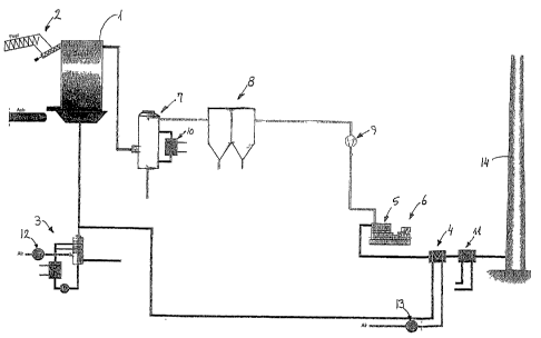
Fig. 1 schematically shows an embodiment of an apparatus for generating
electric
power in accordance with the present invention.
CA 02656352 2008-12-29
WO 2008/004070 PCT/1B2007/001793
4
Fig. 2 is a curve diagram showing the stable production of electric power by
varying
the gas control valve opening.
DESCRIPTION OF THE PREFERRED EMBODIMENT
The apparatus for generating electric power shown in Fig. 1 comprises a
gasifier 1
of the shaft and updraft fixed bed type, in which raw material for
gasification is
charged from the top by means of a charging conveyor 2. Gasifying agent is
intro-
duced from the bottom of the gasifier 1 and the gasifying agent comprises
humidi-
fied and preheated air delivered from a humidifier 3 and a preheater 4. The
gas pro-
duced in the gasifier 1 is delivered to a gas engine 5 driving a generator 6
for pro-
ducing electrical power. Gas cleaning equipment in the form of a gas cooling
system
7 and an electrostatic precipitator 8 is provided between the gasifier 1 and
the gas
engine 5 in order to provide a clean gas for the gas engine 5. Furthermore, a
fan 9
increases the pressure of the fuel gas delivered to the gas engine 5, said fan
9 be-
ing controlled to deliver a constant pressure and being followed by a gas
control
valve varying the fuel gas flow for this purpose. The gas cooling system 7 is
con-
nected to a heat exchanger 10 in order to utilize the energy removed from the
gas in
the gas cooling system 7. The heat exchanger 10 may be integrated in the gas
cooling system 7 and the gas cooling system 7 may comprise a further gas
cooling
tower in order to reduce the temperature of the fuel gas and extract further
conden-
sate from the fuel gas. Condensate from the gas cooling system 7 is taken out
therefrom and possibly utilized as supply water for the humidifier 3 after
cleaning,
such cleaning possibly including separation of tar and other combustible
condensate
products. The electrostatic precipitator 8 removes possible further
particles/aerosols
present in the fuel gas before delivery to the gas engine 5. The exhaust gas
from the
gas engine 5 may be utilized in the preheater 4 for preheating air for use as
gasify-
ing agent and possible further heat may be extracted in a separate heat
exchanger
11 before delivery of the exhaust gases to the flue stack 14. The preheated
secon-
dary air from the heat exchanger 4 is delivered to the bottom of the gasifier
1, either
directly, as shown in Fig. 1, or in combination with primary air humidified in
a hu-
midifier 3 possibly comprising a separate air fan and a water circulation
system, in
which the water is heated, possibly using the excess heat from the gas cooling
sys-
CA 02656352 2008-12-29
WO 2008/004070 PCT/1B2007/001793
tern 7 via the heat exchanger 10 and/or the excess heat from the exhaust gas
from
the gas engine 5 delivered from the heat exchanger 11.
The gasifying agent in the form of humidified primary air and secondary air is
deliv-
5 ered to the bottom of the gasifier in controlled amount by controlling
the separate
fans 12, 13 for primary air and secondary air, respectively, and the
humidification is
controlled by controlling the heat delivered to the circulated water in the
humidifier 3,
whereby a controlled amount of gasifying agent having a controlled humidity
can be
delivered to the gasifier 1.
As shown in Fig. 2, the typical electrical power production curve over time
indicates
that a constant electrical power can be maintained over a substantial period.
The
periodical variations in the gas control valve position are related to
periodic infeed of
biomass material by the charging conveyor 2.
Typical parameters for the primary air is water-saturated air at 70 C and for
secon-
dary air dry air at 400 C, said primary air and secondary air being mixed for
use as
gasifying agent at 120 C.
During operation, the gas engine 5 and the generator 6 are controlled to
deliver the
desired electrical power, and the fan 9 is controlled to deliver fuel gas to
the gas en-
gine 5 at a constant pressure. Furthermore, the gasifier 1 is controlled by
means of
the fans 12, 13 for primary air and secondary air, respectively, to deliver
fuel gas at
the top of the gasifier at a constant pressure, said pressure preferably being
main-
tamed close to the ambient atmospheric pressure, preferably at 0-5 mm WG and
more preferably at 0-1 mm WG below the ambient atmospheric pressure. In other
words, controlling of the generated power is performed by the control of the
position
of the gas control valve. Changes in the position of this gas control valve
induce a
change in the control of the fan 9 maintaining a constant pressure to this gas
control
valve, and this will induce a change of the speed of the fans 12, 13 for
primary and
secondary air, respectively, in order to maintain the constant pressure of the
deliv-
ered fuel gas at the top of the gasifier. By this mode of controlling the
fixed bed up-
draft gasifier, the following functional parameters have been obtained:
Control range of generated electrical power: 10% - 100% of maximum power.
CA 02656352 2008-12-29
WO 2008/004070 PCT/1B2007/001793
6
Increase rate of generated electrical power: Approx. 10% of maximum power/ min-
ute.
Decrease rate of generated electrical power: Approx. 35% of maximum power/ min-
ute.
Less than 10% of maximum power may theoretically be controlled, but this would
be
without practical interest due to a relatively high heat loss, etc.
The two fans 12, 13 for primary and secondary air, respectively, are
controlled indi-
vidually in order to optimize the gasification in the gasifier 1 providing the
gasifying
agent having a temperature and humidity optimized to the process. Said
parameters
will evidently depend on the delivered biomass material from the charging
conveyor
2, i.e. the humidity of said biomass material and the constituents thereof.
The infeed
of biomass by the charging conveyor 2 is controlled to maintain a
substantially con-
stant level of the biomass in the gasifier, e.g. by having a levelling
impeller at the top
of the gasifier distributing the biomass over the upper surface thereof, and
control-
ling the charging conveyor 2 in dependence of the resistance encountered by
the
levelling impeller. At the bottom of the gasifier 1, ashes are taken out and
disposed
of in the normal way. Preferably the gasifier 1 is controlled in such a way
that the
temperature of the fuel gas at the top of the gasifier is below 100 C.,
typically ap-
proximately 75 C.
Above, the invention has been described in connection with a preferred
embodiment
thereof, however, many modifications may be envisaged without departing from
the
following claims, such deviations among others including the use of more than
one
gas engine 5 and generator 6 for producing electrical power and possible use
of
some of the fuel gas from the gasifier in a boiler for producing district
heating, said
boiler possibly using fuel gas directly from the gasifier without gas
cleaning. Fur-
thermore, the condensate from the gas cooling system 7 being tar water may be
cleaned by separating tar from the water and cleaning the water, as described
in
European patent No. 1,395, 519 owned by the applicant of the present
application.
CA 02656352 2008-12-29
WO 2008/004070 PCT/1B2007/001793
7
The separated tar may be used as fuel or used as raw material for
gasification.
Further heat exchangers may be inserted after the heat exchanger 11 and
between
the gas cooling system 7 and the electrostatic precipitator 8 in order to
obtain a
suitably low exhaust gas temperature in the stack 14 and at the electrostatic
pre-
cipitator 8, respectively. The heat extracted in the several heat exchangers
may be
used for district heating. Typical temperature of the fuel gas at the entrance
to the
electrostatic precipitator 8 is 35 C and at the outlet therefrom 40 C, and
the fan 9
will raise the temperature further to approx. 60 C at the delivery to the gas
engine,
thus avoiding any risk of condensation of the fuel gas. The temperature of the
gasifi-