Note: Descriptions are shown in the official language in which they were submitted.
CA 02656418 2014-03-05
79291-80
1
DESCRIPTION
METHOD FOR OPERATING A GAS TURBINE AND ALSO GAS TURBINE
FOR CARRYING OUT THE METHOD
Technical field
The present invention refers to the field of technology
of gas turbine installations. It relates
to a method
for operating a gas turbine, and also to a gas turbine for
carrying out the method.
Background of the invention
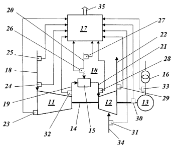
A gas turbine installation for generating electric
power customarily comprises according to Fig. 1 a
compressor 11 which draws in air from the environment
via a compressor inlet 18, compresses this, and
delivers the compressed air via a compressor outlet 19
to a subsequent combustion chamber 15 where it is used
for combusting a liquid or gaseous fuel which is
introduced through a fuel feed line 20. The hot gas
which results during the combustion is transmitted via
a turbine inlet 21 to a turbine 12 which is connected
downstream, where it is expanded, performing work. The
expanded gas is discharged as exhaust gas at a turbine
exhaust 22. Via a common shaft 14, the turbine 12
drives both the compressor 11 and a generator 13, at
the terminals of which electric power can be tapped and
transmitted via a transformer 16 to a local or national
power supply network.
The output power of the gas turbine installation at the
generator terminals is one of the main control
parameters of the power plant. If the
gas turbine is
part of a so-called "power island" (note: an isolated
CA 02656418 2008-12-30
2
local network, which is separated from the national
grid, with limited electrical capacity is to be
understood by "power island" in this connection;
typical examples of power islands are metallurgical
plants, paper mills or rolling plants), the controlling
of the gas turbine and its precise and reliable
operation takes place in an environment which is
characterized by a continuous power demand of the
individual, often fluctuating consumers on the power
island. In such a complex environment, the controlling
of the gas turbine requires particular attention.
While the efficient and accurate controlling of a gas
turbine installation in a generally "rigid" national
grid already represents a challenge, the requirements
increase if a comparatively smaller isolated local
network with individual consumers and associated
critical processes is to be operated and kept alive.
The controlling of the gas turbine installation
especially requires improved and further developed
control strategies for modern gas turbine installations
during faster transition phases with potential network
frequency fluctuations.
A special demand upon gas turbine controlling in
isolated power islands with potential network frequency
fluctuations results from the fact that the active
power at the generator terminals (PGENo) comprises a
kinetic power (P
KINETIC) KINETIC ) in addition to the thermal power
(PGT) of the gas turbine, which kinetic power is
proportional both to the time derivative of the network
frequency (dn/dt) and to the total inertia moment
(JISLAND) of the consumers which are connected up to the
island during such an event.
A device for calculating the mechanical output power of
a gas turbine is known from publication US-Al-
2005/0131616, in which by means of a wattmeter and a
CA 02656418 2014-03-05
79291-80
3
tachometer the electric power at the generator
terminals and the speed of the turbine are measured,
and from the two values the mechanical Output power of
the turbine is calculated by means of an equation.
This solution is dependent upon measuring at the
generator terminals and therefore cannot be applied in
cases in which this measuring cannot be carried out, is
not quick enough, or is falsified by interruptions.
This is especially the case with the aforementioned
power islands.
A method for controlling the power of a turbogroup is
known from EP-A1-0 903 469, in which the power which is
delivered by the generator is determined and the
thermal power of the turbine is controlled in
dependence upon the measured electric power of the
generator, wherein the kinetic power which is absorbed
or delivered by the shaft is additionally determined
and the thermal power is controlled in accordance with
the sum of the electric power and kinetic power. The
electric power in this case can especially be
calculated from the rotational frequency of the shaft
and the torque acting on the shaft. This solution is
not suitable for power islands either.
ak 02656418 2016-08-22
74278-63
4
Summary of the invention
Embodiments of the invention may provide a method for operating
a gas turbine, and also a gas turbine for carrying out the
method, which avoid the disadvantages of known solutions and
which are especially suitable for installations which are used
in power islands.
According to an aspect, there is provided a method for
operating a gas turbine, which comprises a compressor for
compressing combustion air which is drawn in from the
environment, a combustion chamber for combusting supplied fuel
by means of the compressed combustion air, a turbine which is
driven by hot gas from the combustion chamber, and a generator,
which is driven by the turbine, for generating electric power,
the method comprising: providing at least one transducer for
measuring or determining at least the following parameters of
the gas turbine, specifically a temperature (T2) at an inlet of
the compressor, a total or static absolute or gauge pressure
(p3) at an outlet of the compressor, a speed (nGT) of the gas
turbine or a frequency of a power supply network to which the
gas turbine feeds power, a measured or predetermined mass flow
(Infuel) of the fuel which is fed to the combustion chamber, and
a lower heating value (LHV) of the fuel wherein from the
measured or determined parameters an effective thermal output
power (PGT) of the gas turbine is calculated, wherein the
effective thermal output power (PGT) of the gas turbine is
approximated by a mathematical function of the following type:
PGT afl (133) f2 (Infuei) = f3 (LHV) = f4 (n
--GT) = f5 (T2)
CA 02656418 2016-08-22
I t.
74278-63
4a
wherein fl,..,f5 are functions which are to be determined for
respective cases, p3 is the compressor outlet pressure, m
¨fuel i
the fuel mass flow, LHV is the lower heating value of the fuel,
and nGT is the speed of the gas turbine, and wherein the
calculated effective thermal output power (PGT) is used for
controlling the gas turbine.
A further aspect provides a method for operating a gas turbine,
which comprises a compressor for compressing combustion air
which is drawn in from the environment, a combustion chamber
for combusting supplied fuel by means of the compressed
combustion air, a turbine which is driven by hot gas from the
combustion chamber, and a generator, which is driven by the
turbine, for generating electric power, the method comprising:
providing at least one transducer for measuring or determining
at least the following parameters of the gas turbine,
specifically an ambient temperature (TI), a total or static
absolute or gauge pressure (p3) at an outlet of the compressor,
a speed (nGT) of the gas turbine or a frequency of a power
supply network to which the gas turbine feeds power, a measured
or predetermined mass flow (mfuei) of the fuel which is fed to
the combustion chamber, and a lower heating value (LHV) of the
fuel wherein from the measured or determined parameters an
effective thermal output power (PGT) of the gas turbine is
calculated, wherein the effective thermal output power (PGT) of
the gas turbine is approximated by a mathematical function of
the following type:
PGT af 1 (P3) ' f2 On fuel) = f3 (LHV) = f4 (nGT) = f5 (Ti)
wherein fl,..,f5 are functions which are to be determined for
respective cases, p3 is the compressor outlet pressure, m
¨fuel is
CA 02656418 2016-08-22
74278-63
4b
the fuel mass flow, LHV is the lower heating value of the fuel,
and ngr is the speed of the gas turbine, and wherein the
calculated effective thermal output power (Pm) is used for
controlling the gas turbine.
There is also provided a method for operating a gas turbine,
which comprises a compressor for compressing combustion air which
is drawn in from the environment, a combustion chamber for
combusting supplied fuel by means of the compressed combustion
air, a turbine which is driven by hot gas from the combustion
chamber, and a generator, which is driven by the turbine, for
generating electric power, wherein one or more of the following
parameters of the gas turbine, specifically an ambient
temperature (T1), a temperature (T2) at an inlet of the
compressor, a temperature at an outlet of the compressor, a
turbine exhaust temperature, an ambient air pressure, a total or
static absolute or gauge pressure (p3) at the compressor outlet, a
total or static absolute or gauge pressure at an inlet of the
turbine, a pressure loss between the compressor outlet and the
turbine inlet, a speed (nm) of the gas turbine or a frequency of
a power supply network to which the gas turbine feeds power, a
measured or predetermined mass flow (mthel) of the fuel which is
fed to the combustion chamber, and a lower heating value (LHV) of
the fuel are measured or determined, wherein from the measured or
determined one or more parameters an effective thermal output
power (Pm) of the gas turbine is calculated, and wherein the
calculated effective thermal output power (PGT) is used for
controlling the gas turbine, wherein the effective thermal output
power (PGT) of the gas turbine is continuously measured, the
measured value of the effective thermal output power (Pm) is used
for controlling the gas turbine if the gas turbine is in a steady
operating state, and wherein the calculated value of the
CA 02656418 2016-08-22
t.
74278-63
4c
effective thermal output power (PGT) is used if the gas turbine is
in a fast changing transition state, the power supply network is
unstable, or both.
In accordance with still further aspect, there is provided a gas
turbine for carrying out such a method, comprising the compressor
for compressing the combustion air which is drawn in from the
environment, the combustion chamber for combusting the supplied
fuel by means of the compressed combustion air, the turbine which
is driven by the hot gas from the combustion chamber, and the
generator, which is driven by the turbine for generating electric
power, wherein a control unit is provided for controlling
operation of the gas turbine, wherein at associated points of the
gas turbine the at least one transducer is provided for measuring
or determining the parameters, and are connected to the control
unit, and wherein the control unit is designed for calculating
the effective thermal output power (PGT) of the gas turbine from
the measured or determined parameters.
According to another aspect, there is provided a gas turbine for
carrying out such a method, comprising the compressor for
compressing the combustion air which is drawn in from the
environment, the combustion chamber for combusting the supplied
fuel by means of the compressed combustion air, the turbine which
is driven by the hot gas from the combustion chamber, and the
generator, which is driven by the turbine for generating electric
power, wherein a control unit is provided for controlling
operation of the gas turbine, wherein at associated points of the
gas turbine at least one transducer is provided for measuring or
determining the one or more parameters, and connected to the
control unit, and wherein the control unit is designed for
calculating the effective thermal output power (PGT) of the gas
turbine from the measured or determined one or more parameters.
CA 02656418 2016-08-22
74278-63
4d
=
According .to one. embodiment of. the invention,, the
compressor comprises variable inlet guide vanes and the
position of the variable inlet guide vanes is taken
into consideration as a further parameter = when
0 calculating the effective thermal output power.
Another embodiment of the invention is characterized in
that a cooling medium, especially water or steam, is
fed to the gas turbine at a chosen point, and in that
the mass flow of the cooling medium is taken into
consideration as a further parameter when calculating
=
the effective thermal output power. =
=
A preferred embodiment of the invention .is
characterized in that the effective thermal output
power of the gas turbine is calculated in accordance
with the equation
=
=
CA 02656418 2008-12-30
PGT a fi (P3) f2 (nfuel) = f3 (LHV) = f4 (nGT) = f5 (T2)
wherein fl,..,f5 are functions which are to be
5 determined for the respective case, p3 is the
compressor outlet pressure, Mfuel is the fuel mass flow,
LHV is the lower heating value of the fuel, nGT is the
speed of the gas turbine, and T2 is the compressor
inlet temperature.
In this case, the ambient temperature can especially be
used as a variable in the equation instead of the
compressor inlet temperature as long as available
devices for cooling or for preheating the ambient air
which is drawn in by the compressor are not activated.
A preferred embodiment is characterized in that for
taking into consideration ageing effects and other
changes in the gas turbine the effective thermal output
power of the gas turbine is measured at determined time
points, and in that the coefficients which occur in the
equation are adjusted by comparison with the calculated
effective thermal output power. Furthermore, the lower
heating value of the fuel in the equation can also be
adjusted from time to time.
A further embodiment of the invention is characterized
in that the effective thermal output power of the gas
turbine is continuously measured, in that for the
controlling of the gas turbine the measured or
calculated value of the effective thermal output power
is selectively used, and in that the controlling of the
gas turbine is automatically changed over from one to
the other value depending upon the state of the gas
turbine and of the power supply network.
The measured value of the effective thermal output
power can especially be used in this case for
controlling the gas turbine if the gas turbine is in a'
CA 02656418 2008-12-30
6
steady operating state, and the calculated value of the
effective thermal output power is used if the gas
turbine is in a fast changing transition state and/or
the power supply network is unstable.
An embodiment of the gas turbine according to the
invention is characterized in that the compressor
comprises variable inlet guide vanes, and in that a
transducer, which is connected to the control unit, is
arranged on the compressor for sensing the position of
the variable inlet guide vanes.
Another embodiment is characterized in that devices for
cooling the gas turbine by means of a cooling medium
are provided on the gas turbine, and in that a
transducer, which is connected to the control unit, is
arranged on the gas turbine for measuring the mass flow
of the cooling medium.
According to a further embodiment of the invention,
means, which are connected to the control unit, are
attached on the terminals of the generator for
measuring the power which is delivered at the generator
terminals.
In this case the invention is not limited to a gas
turbine according to the description and figure which
follow here, but it also covers gas turbines with a
sequential firing, as originates from EP-B1-0620362.
This whole publication in this case forms an integral
part of this application.
Brief explanation of the figures
The invention is to be subsequently explained in more
detail based on exemplary embodiments in conjunction
with the drawing. The single figure shows a connection
diagram of a gas turbine with a control unit according
CA 02656418 2008-12-30
7
to a preferred exemplary embodiment of the invention.
Ways of implementing the invention
The invention is based on the fact that, as already
further mentioned above, the active power at the
generator terminals (PGENO) comprises a kinetic power
(PKINETTc) in addition to the thermal power (PGT) of the
gas turbine, which kinetic power is proportional both
to the time derivative of the network frequency (dn/dt)
and to the total inertia moment ( JISLAND ) of the
consumers which are connected up to the island during
such an event.
Since the inertia moment is to be predicted only with
difficulty due to the practically unlimited combination
possibilities of the individual consumers, it is
simpler to determine the effective thermal power ( PGT )
by means of suitable physical/mathematical methods as
input values for the control system of the gas turbine.
The physical formulation for the description of the
aforementioned transient effects uses the following
equation:
(1) PGENO = PGT PKINETIC = PGT ' 7
ISLAND -11.(dn)
dt
wherein the equation for the steady state can be
simplified to
(2) PGENO = PGT
The proposed method is based on the determining of the
effective thermal output power of the gas turbine by
means of various measured characteristic parameters..
Taking into consideration the thermodynamics of an open
gas, turbine cyclic process (Joule-Brayton cyclic
CA 02656418 2008-12-30
8
process), the thermal output power of a gas turbine in
simple values follows the relationship
(3) PGT a Mexh (h6 h7) r
wherein the indices "6" and "7" refer to the conditions
at the turbine inlet (21) and turbine exhaust (22).
In the case of an idealized uncooled turbine, the value
Mexh represents the total exhaust gas flow which passes
through the turbine (12), while the inlet enthalpy h6
is linked with the turbine inlet temperature (TIT)
according to international standard ISO 2314:1989.
If a constructed gas turbine with a prespecified
swallowing capacity and a defined operating concept is
taken as a starting point, the operating range of the
gas turbine is consequently established, and the
thermal output power of the gas turbine can be
approximated by a mathematical function of the
following type:
(4) PGT a fl(p3)=f2(rn
,---fuel) =
The compressor outlet pressure p3 in the equation (4)
= is directly linked with the exhaust gas mass flow m
¨exhr
while the fuel mass flow m
¨fuel represents a suitable
measurement for the firing degree of the gas turbine,
i.e. for the inlet enthalpy h6 from equation (3).
In order to compensate for possible fluctuations in the
lower heating value (LHV) of the fuel, the equation (4)
can be expanded as follows:
(5) PGT a f / (P3) = f 2 (Infuei) -f3(LHV).
If, furthermore, fluctuations are to be compensated for
in the network frequency (which are equivalent to the
relative change in the rotor speed of the gas turbine),
CA 02656418 2008-12-30
9
and changes in the ambient temperature are to be taken
into consideration, the following equation finally ,
results from the equation (5):
(6) PGT a fl (p3) =f2(Infue1) =f3 (LHV) =f4(nGT) =f5 (Ti) =
If the ambient temperature T1 is substituted by the
compressor inlet temperature T2, there finally follows:
(7) PGT a fl (33) =f2(111fuei) -f3(LHV) =f4(nGT) =f5 (T2) =
The last-mentioned equation (7) can be referred to as a
so-called "power formula".
The most suitable structure of the functions fl,..,f5
in equation (7) follows from the specific operating
characteristic of the respective gas turbine and must
be determined individually on the basis either of
suitable calculations of the cyclic process or from
direct measurements on the gas turbine.
If the functions fl,..,f5 of the equation (7) are
defined in a suitable manner, the correlation for the
effective thermal power according to equation (6) or
(7) can be integrated in a simple manner into the
control system of the gas turbine, in which the
following parameters are measured individually or in
combination and processed in the control unit of the
gas turbine:
- the ambient temperature T1,
- the compressor inlet temperature T2,
- the compressor outlet temperature
- the turbine exhaust temperature
- the ambient air pressure
- the total or static absolute or gauge pressure
p3 at the compressor outlet 19,
- the total or static absolute or gauge pressure
at the turbine inlet 21,
- the pressure loss between compressor outlet 19
CA 02656418 2008-12-30
and turbine inlet 21,
- the speed nGT of the gas turbine 10 or the
frequency of the power supply network,
- the position of the variable inlet guide vanes
5 VIGV of the compressor 11,
- the measured or predetermined mass flow m
¨fuel of
the fuel which is fed to the combustion chamber
15,
- the measured or predetermined mass flow of the
10 water or steam if either of these is
additionally injected into a component of the
gas turbine; and
- the lower heating value (LHV) of the fuel on
the basis of for example an online gas
chromatograph (GC).
In order to provide corresponding parameter values for
the control unit 17, according to the figure various
transducers 23,..,32 are provided in a distributed
manner in the gas turbine 10 and are connected to the
control unit 17:
-. the transducer 23 is provided for the position
= of the variable inlet guide vanes VIGV of the
compressor 11;
- the transducers 24 at the compressor inlet 18
are provided for the pressure and/or for the
temperature at the compressor inlet 18;
- the transducer 25 is provided for the ambient
temperature Tl and/or for the ambient air
pressure;
- the transducer 26 on the fuel feed line 20
measures the fuel mass flow m
¨fuel ;
- the transducer 27 on the fuel feed line 20 for
example is formed as a gas chromatograph and
measures the lower heating value LHV of the
fuel;
- the transducer 28 which is arranged at the
turbine inlet 21 measures the turbine inlet
pressure;
CA 02656418 2008-12-30
11
- the transducer 29 which is arranged at the
turbine exhaust 22 is provided for measuring
the turbine exhaust temperature;
- the transducer 30 which is arranged on the
shaft 14 senses the speed of the shaft 14;
- the transducer 31 which is arranged on the
cooling medium feed line 34 measures the mass
flow of the cooling medium;
- the transducer 32 which is provided at the
compressor outlet 19 measures the compressor
outlet temperature and the compressor outlet
pressure; and
- the transducer which is arranged on the
generator terminals measures the electric power
at the generator terminals.
From the incoming measured values the control unit
calculates the effective thermal power of the gas
turbine 10 in accordance with the equations (6) or (7),
and from it derives control signals which are delivered
at the output 35 of the control unit for controlling
the gas turbine 10 in a manner known per se.
It can be advantageous within the scope of the
invention if the "power formula" according to equation
(6) or (7) is adapted continuously (online adaptation)
to permanent or temporary changes in the gas turbine
10. Thus, it is difficult to incorporate ageing
effects and the thermal state of the gas turbine into
the "power formula" from the outset. The
calculated
power, therefore, will not be exactly the same as the
power which is measured by means of the transducer 33.
In this case, assistance can be created by the
coefficients of the "power formula" being automatically
altered online in order to correlate the measured power
with the calculated power.
In case the lower heating value LHV of the fuel is not
measured online by means of a gas chromatograph, or the
CA 02656418 2008-12-30
12
delay time of the gas chromatograph is too long, it is
practical to correspondingly adjust the lower heating
value LHV in the "power formula".
If the gas turbine 10 is in a steady state or stable
state, the power which is measured at the generator
terminals is of higher accuracy. If, on
the other
hand, the gas turbine 10 is in a fast changing
transient operating state, or if the network is
unstable, the inaccuracy of the measured power is
great. This inaccuracy can have the following causes:
- the lacking dynamics of the power measuring
(i.e. the measuring is not quick enough);
- and/or the kinetic power of the power train.
In these cases, the calculated power can be used for
controlling the gas turbine 10 instead of the measured
power. An automatic switching can be provided in the
control unit 17 so as to use the suitable power value
(measured or calculated) in accordance with the
operating state of the gas turbine 10 and of the
network.
The described method can not only be advantageously
used in power islands but can generally be used in the
following situations:
1. The active power of the gas turbine cannot be
directly measured at the generator terminals
(PGENo) = This is especially the case with
a. a gas turbine operation for supporting
a power island, i.e. especially during
fast transient operating states and/or
network fluctuations;
b. gas turbine operation in a combined
cycle power plant with a single-shaft
configuration.
2. The measuring of the active power at the
generator terminals (PGENo) is not quick enough.
3. The measuring of the active power at the
generator terminals (PGENo) is interrupted.
CA 02656418 2008-12-30
13
In all, a gas turbine operation is created with the
invention in which the controlling both in the steady
state and in transient operating states is improved and
the availability and reliability especially of the
critical local isolated networks ("power islands") is
increased.
CA 02656418 2008-12-30
14
List of designations
Gas turbine
11 Compressor
12 Turbine
13 Generator
14 Shaft
Combustion chamber
16 Transformer
17 Control unit
18 Compressor inlet
19 Compressor outlet
Fuel feed line
21 Turbine inlet
22 Turbine exhaust
23,.33 Transducer
34 Cooling medium feed line
35 Control output
=