Note: Descriptions are shown in the official language in which they were submitted.
CA 02656437 2009-02-27
DEVICE AND MEDICAL INSTRUMENT FOR PREVENTING
EXCESSIVE INSERTION OF A ROD-LIKE MEMBER
FIELD OF THE INVENTION
[0001] The present invention relates to a device for preventing excessive
insertion
which is used when a rod-like member is inserted into a gastrostomy catheter
which is
positioned in a fistula formed in a patient's body, and to a medical
instrument provided with
the same.
BACKGROUND OF THE INVENTION
[0002] It is conventional practice to position a gastrostomy catheter in a
fistula
formed in a patient's body, and to insert an endoscope into the gastrostomy
catheter to
observe the inside of the stomach as well as to confirm the position of the
gastrostomy
catheter. In such cases, it is necessary to change the orientation of the tip
end of the
endoscope so as to be able to see in various directions in order to accurately
confirm the state
of the inside of the stomach and position of the gastrostomy catheter.
Consequently, a
bending instrument or the like which can change the orientation of the tip end
of the
endoscope is used when the endoscope is inserted a prescribed length into the
gastrostomy
catheter. In such cases, if more than is necessary of the endoscope is
inserted into the stomach
from the gastrostomy catheter, the bent portion of the endoscope grows larger,
making it
impossible to make accurate observations. Additionally, the endoscope may be
damaged.
[0003] In order to prevent this, it has been envisaged to prevent the
endoscope from
being inserted beyond a prescribed length into the gastrostomy catheter using
a stopper, or
the like (see Japanese Unexamined Utility Model Registration Application H1-
130317, for
example). The laser probe disclosed in H 1-130317 consists of a probe main
body in which an
optical fiber serves as a light guide. The probe main body has a configuration
in which it is
inserted into the endoscope for use. A stopper or the like is then fixed to a
prescribed portion
of the probe main body, and it is possible to regulate the probe main body by
means of the
stopper so that it is not inserted more than necessary into the endoscope.
[0004] However, with the laser probe mentioned above, when the probe main body
is inserted into endoscopes of different lengths, the length of the tip end
portion of the probe
main body which projects from the tip end of the endoscope may be too great or
too small.
Consequently, when the laser probe is inserted into the stomach via the
gastrostomy catheter,
the tip end of the laser probe cannot be inserted into the stomach to a
suitable length in
1
CA 02656437 2009-02-27
accordance with the length of the gastrostomy catheter. Furthermore, it is not
just the
endoscope which is inserted into the gastrostomy catheter, but also a push-
rod, for example,
for making the stomach-internal fixed part extend in an elongate fashion when
the
gastrostomy catheter is positioned in the fistula formed in the body of the
patient. Here too it
is necessary to insert the push-rod to a suitable length in accordance with
the length of the
gastrostomy catheter.
SUMMARY OF THE INVENTION
100051 In one aspect of the present invention, a device is used for preventing
excessive insertion when a rod-like member is inserted into a gastrostomy
catheter
comprising a tubular part and a stomach-internal fixed part. The fixed part
comprises an
expanded body which links with a tip end of the tubular part. The tip end is
provided with a
through-hole, and said fixed part extends in an elongate fashion due to a
portion on a
through-hole side being pushed in the direction of a tip end side. The device
generally
comprises a reference position establishment part which can be installed at a
prescribed
portion on a base end opening side of the gastrostomy catheter in a state in
which it can move
in a longitudinal direction of the rod-like member. A mobile part can be fixed
to a prescribed
portion of the rod-like member. A linking part can change a gap between the
reference
position establishment part and the mobile part within a range which is no
greater than a set
length, and links the reference position establishment part and the mobile
part.
[0006] In another aspect of the present invention, a medical instrument in
combination with the device described in the preceding paragraph.
[0007] Other objects and features will be in part apparent and in part pointed
out
hereinafter.
BRIEF DESCRIPTION OF THE DRAWINGS
[0008] FIG. 1 shows a gastrostomy catheter, where (a) is a plan view, (b) is a
front
view, and (c) is a bottom view.
100091 FIG. 2 is a front view showing a state in which the device for
preventing
excessive insertion according to the first embodiment of the present invention
is fitted to an
endoscope.
[0010] FIG. 3 is a front view showing the endoscope.
2
CA 02656437 2009-02-27
[0011] FIG. 4 shows the device for preventing excessive insertion according to
the
first embodiment of the present invention, where (a) is a plan view, (b) is a
front view, (c) is a
side view, and (d) is a bottom view.
[0012] FIG. 5 shows a state in which the mobile part of the device for
preventing
excessive insertion according to the first embodiment has moved to the
reference position
establishment part side, where (a) is a front view, and (b) is a side view.
[0013] FIG. 6 is an oblique view showing a bending instrument.
[0014] FIG. 7 is a fragmentary cutaway in cross section showing a state in
which
the endoscope, to which the device for preventing excessive insertion
according to the first
embodiment is fitted, is positioned above the gastrostomy catheter in the
patient's body.
[0015] FIG. 8 is a fragmentary cutaway in cross section showing a state in
which
the endoscope, to which the device for preventing excessive insertion
according to the first
embodiment is fitted, is inserted into the gastrostomy catheter in the
patient's body.
[0016] FIG. 9 is a fragmentary cutaway in cross section showing a state in
which
the position of the gastrostomy catheter is confirmed using the endoscope to
which the device
for preventing excessive insertion according to the first embodiment is
fitted.
[0017] FIG. 10 shows the device for preventing excessive insertion according
to a
second embodiment of the present invention, where (a) is a plan view, (b) is a
front view, and
(c) is a bottom view.
[0018] FIG. 11 is a fragmentary cutaway in cross section showing a state in
which
the endoscope, to which the device for preventing excessive insertion
according to the second
embodiment is fitted, is inserted in the gastrostomy catheter in the patient's
body.
[0019] FIG. 12 is a fragmentary cutaway in cross section showing a state in
which
the position of the gastrostomy catheter is confirmed using the endoscope to
which the device
for preventing excessive insertion according to the second embodiment is
fitted.
[0020] FIG. 13 is a front view showing the device for preventing excessive
insertion
according to a third embodiment of the present invention.
[0021] FIG. 14 is a front view showing a state in which the linking part of
the
device for preventing excessive insertion according to the third embodiment of
the present
invention is in a contracted state.
[0022] FIG. 15 is a fragmentary cutaway in cross section showing a state in
which
the endoscope, to which the device for preventing excessive insertion
according to the third
embodiment is fitted, is inserted in the gastrostomy catheter in the patient's
body.
3
CA 02656437 2009-02-27
[0023] FIG. 16 is a fragmentary cutaway in cross section showing a state in
which
the position of the gastrostomy catheter is confirmed using the endoscope to
which the device
for preventing excessive insertion according to the third embodiment is
fitted.
[0024] FIG. 17 shows the device for preventing excessive insertion according
to a
fourth embodiment of the present invention, where (a) is a plan view, (b) is a
front view, and
(c) is a bottom view.
[0025] FIG. 18 is an oblique view showing the fitting instrument which is used
according to the fourth embodiment of the present invention.
[0026] FIG. 19 is a front view showing a state in which the push-rod of the
fitting
instrument to which the device for preventing excessive insertion according to
the fourth
embodiment is attached is inserted in the gastrostomy catheter.
[0027] FIG. 20 is a front view showing a state in which the stomach-internal
fixed
part of the gastrostomy catheter is extended using the fitting instrument to
which the device
for preventing excessive insertion according to the fourth embodiment is
attached.
100281 FIG. 21 is a fragmentary cutaway in cross section showing a state in
which
the stomach-internal fixed part of the gastrostomy catheter has entered the
stomach by means
of the fitting instrument to which the device for preventing excessive
insertion according to
the fourth embodiment is attached.
100291 Corresponding reference characters indicate corresponding parts
throughout
the drawings.
DESCRIPTION OF THE PREFERRED EMBODIMENTS
[0030] A first embodiment of the present invention is described below using
the
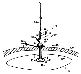
figures. Figure 1 shows a gastrostomy catheter 10 pertaining to the first
embodiment. Figure
2 shows a state in which a device 30 for preventing excessive insertion, a
bending instrument
40, and an insertion aid 50 etc. are fitted to an endoscope 20 which acts as
the rod-like
member according to the present invention which is inserted into the
gastrostomy catheter 10.
The medical instrument according to the first embodiment comprises the
gastrostomy
catheter 10, endoscope 20, device 30 for preventing excessive insertion,
bending instrument
40 and insertion aid 50, among other things. The gastrostomy catheter 10
consists of an
external fixed part 11, a tubular part 12 which is linked to the centre of the
lower surface of
the external fixed part 11, and a stomach-internal fixed part 13 which is
attached to the lower
end of the tubular part 12. All the components are made of a soft plastic
material such as
polyurethane or silicone.
4
CA 02656437 2009-02-27
100311 In the description that follows, the external fixed part 11 will be
referred to
as the upper side, and the stomach-internal fixed part 13 will be referred to
as the lower side.
The external fixed part 11 comprises an insertion opening I 1 a which is
annular and fairly
thick, and projecting pieces l lb, 1 lc which project at both sides from the
lower end of both
side parts of the insertion opening l la. The outline of the portion including
the projecting
pieces Ilb, Ilc and the insertion opening Ila is elliptical, when seen as a
plane, and the
function of these projecting pieces I lb, l lc is to prevent the gastrostomy
catheter 10 from
being pulled into the stomach S (see FIGs. 7 to 9). A valve body 14a which is
formed with a
central slit is then provided on the inner peripheral surface of an insertion
hole 14 which is
formed in the centre of the insertion opening 11 a, passing through
vertically. Furthermore, an
engagement groove is formed along the circumference at the upper side of the
valve body 14a
on the inner peripheral surface of the insertion hole 14, although this is not
depicted.
[0032] A cover part 15 for closing off the insertion hole 14 of the insertion
opening
I la is then joined to the tip end of the projecting piece l lb. The cover
part 15 comprises an
elongate strip-shaped linking part 15a which is linked to the end of the
projecting piece 1 Ib,
and a broad part 15b which is shorter and wider than the strip-shaped linking
part 15a, and is
formed at the tip end of the strip-shaped linking part 15a. A stopper part 16
shaped like a
column which is short in the axial direction is then provided on the broad
part 15b. The strip-
shaped linking part 15a is flexible, and it can flex so as to vertically
rotate, or bend at a sharp
angle, with the linking part to the projecting piece 1lb at the centre. The
stopper part 16 is
provided on the strip-shaped linking part 15a side portion of the broad part
15b, so as to face
the insertion hole 14 when the strip-shaped linking part 15a is bent to
position the broad part
15b above the insertion opening 11 a.
[0033] The stopper part 16 is formed with a columnar shape which can fit into
the
insertion hole 14, and it is provided on its outer peripheral surface with an
annular projection
16a running along its periphery, the projection being able to detachably
engage with the
engagement groove formed on the inner peripheral surface of the insertion hole
14.
Accordingly, it is possible to engage the engagement groove with the annular
projection 16a
by bending the strip-shaped linking part 15a so that it is upwardly inverted,
and pushing the
stopper part 16 into the insertion hole 14, and this makes it possible to
close off the insertion
hole 14 of the insertion opening 11 a in an airtight and liquid-tight manner.
It is also possible
to open the insertion hole 14 of the insertion opening 11 a by pulling the
broad part 15b to
release the fitting between the stopper part 16 and the insertion hole 14.
CA 02656437 2009-02-27
[0034] The tubular part 12 is formed as a cylindrical shape, and a through-
orifice
(not depicted) for allowing the passage of fluids such as nutrients and food
in fluid form is
formed inside it; the upper end of the through-orifice links in communication
with the
insertion hole 14 of the external fixed part 11. The stomach-internal fixed
part 13 is
connected to the tubular part 12 via a connection part 17 which is fixed to
the lower end of
the tubular part 12. The connection part 17 is formed as a cylinder for
covering the outer
peripheral surface of the tubular part 12 and is integrally formed with the
stomach-internal
fixed part 13. The connection part 17 is fixed to the lower end of the tubular
part 12, in a state
in which it cannot be removed from the tubular part 12.
[0035] The stomach-internal fixed part 13 comprises four strip-shaped linking
parts
13a which are linked to the edge of a lower end opening of the connection part
17 and extend
in four directions, four linking film parts 13b which are provided between the
upper parts of
each of the linking parts 13a and form a substantially dome-shaped stomach
wall contact part
with the four linking parts 13a, and a converging part 13c where the tip ends
of all of the
linking parts 13a converge. The four linking parts 13a comprise strip-shaped
members which
are bent into substantially semi-circular shapes which split into four
directions from the lower
end of the connection part 17, respectively extending downwards from the
horizontal, after
which they converge below the central axis of the tubular part 12, linking to
form the
converging part 13c. In other words, the converging part 13c allows each of
the linking parts
13a to link by joining the lower ends of all of the linking parts 13a, and it
is also positioned
by all of the linking parts 13a below the central axis of the tubular part 12.
[00361 Moreover, the stomach-internal fixed part 13 which comprises the
linking
parts 13a, linking film parts 13b and the converging part 13c is integrally
formed together
with the connection part 17. Furthermore, all of the linking parts 13a and
linking film parts
13b are made of a soft, flexible, elastic material, and the overall flat,
substantially spherical
shape is normally maintained by means of its elasticity, as shown in FIG. 1.
The linking parts
13a and linking film parts 13b can then be extended to make them straight and
elongate by
pulling the converging part 13c downwards. Furthermore, the lower end of the
through-
orifice of the tubular part 12 opens between the upper ends of the linking
parts 13a.
[0037] Spaces formed between the lower parts of each of the linking parts 13a
then
form channels for the passage of fluids such as nutrients and food in fluid
form sent out from
the through-hole of the tubular part 12 into the stomach S. A through-hole 18
is additionally
formed in the centre of the converging part 13c, and a cylindrical engagement
part 18a (see
FIGs. 7 to 9) is formed at the upper part of the through-hole 18 (converging
part 13c). Hence,
6
CA 02656437 2009-02-27
the through-hole 18 is configured by the inner peripheral surface of the
cylindrical
engagement part 18a, and its diameter is smaller than the diameter of the
insertion hole 14 of
the external fixed part I 1 and the diameter of the through-orifice of the
tubular part 12. The
stomach-internal fixed part 13 configured in this manner is positioned on the
inner surface of
the patient's stomach wall SW (see FIGs. 7 to 9) and its function is to
prevent the gastrostomy
catheter 10 from being removed from the patient's body.
[0038) As shown in FIG. 3, the endoscope 20 has a configuration in which a
lens 22
is attached to the tip end of a shaft 21, and a connection part 23 is attached
to the rear end
thereof. The shaft 21 consists of a bundle of fibres comprising a plurality of
light guides (not
depicted) for irradiating light onto the stomach wall SW, and an image guide
(not depicted)
for sending reflected light via the lens, and it is flexible. The connection
part 23 is linked to
wiring 24 which connects the image guide to an image display device (not
depicted), and to
wiring 25 which connects the light guides to a light source device (not
depicted). The lens 22
sends images obtained by the irradiated light to the image display device via
the image guide
and the wiring 24.
[0039] Hence, the light guides irradiate the inner surface of the stomach wall
SW
with light sent from the light source device to make observation possible, and
the image
guide sends the light which is reflected from the inner surface of the stomach
wall SW and
focused by means of the lens 22 to the image display device. The image display
device then
enlarges the images based on the reflected light sent and displays them on an
image display
part provided in the image display device. Furthermore, as shown in FIG. 2,
the shaft 21 is
covered by a sheath 26, and it is possible to prevent soiling of the shaft by
covering it with
the sheath 26. The sheath 26 consists of a tube in which the tip end is closed
off by a light-
transmissive window part (not depicted), and in which the diameter of the base
end 26a on
the opening side is somewhat larger than the other portion, and it is
flexible.
100401 The sheath 26 is formed with a thickness such that it can cover the
shaft 21
in a state in which it is in close contact with the outer peripheral surface
of the shaft 21, and it
is attached to the shaft 21 by pushing the tip-end narrow-diameter part 23a of
the connection
part 23 into the base end 26a. The sheath 26 is prevented from being removed
from the shaft
21 using a member such as a clamp, a fastener, a clasp or the like. When
assembled in this
state, a configuration is adopted so that the lens 22 is in contact with the
inner surface of the
window part. Furthermore, the surface of the window part forms a curving
protrusion which
projects downwards.
7
CA 02656437 2009-02-27
[0041] As shown in FIG. 4, the device 30 for preventing excessive insertion
consists of a reference position establishment part 31, a mobile part 32 and a
linking part 33.
The reference position establishment part 31 consists of an annular body in
the centre of the
disc of which is formed a through-hole 34 through which the shaft 21 which is
covered by the
sheath 26 can pass with clearance. The mobile part 32 consists of a mobile
part main body 35
which is formed with plane parts in which both the left- and right-hand
portions of the disc
(the left- and right-hand side portions in the states shown in FIGs. 4(a) and
(b)) have been cut
away, these plane parts running parallel to each other on both the left- and
right-hand sides,
and guide screws 36 which are each attached to the plane parts of the mobile
part main body
35.
[0042] Furthermore, the diameter at the centre of the mobile part main body 35
is
smaller than the through-hole 34, but a through-hole 37 through which the
shaft 21 covered
by the sheath 26 can pass is formed therein. Screw holes are formed from the
centre of both
plane parts of the mobile part main body 35 towards the inner peripheral
surface of the
through-hole 37, and the guide screws 36 screw into these screw holes. When
one end of the
guide screws 36 is positioned on the inner peripheral surface of the through-
hole 37, the other
end of the guide screws reaches a state in which it protrudes outwards from
the plane parts,
and one end of the guide screws 36 can be made to project into the through-
hole 37 by
turning the guide screws 36 in one direction.
[0043] The linking part 33 is integrally formed with the reference position
establishment part 31, and consists of a pair of rail-like guiding pieces 38
which run
vertically. The outline of the guide pieces 38 has a shape seen from above in
which both
arcuate end parts are joined by a straight line, and seen from the front they
are arranged
laterally symmetrically, comprising members formed as a longitudinal frame
with a gap
between them. Hence, when the mobile part main body 35 has been positioned
between the
pair of guide pieces 38 in a state in which the plane parts of the mobile main
body 35 and the
plane parts of the guide pieces 38 are aligned, the pair of guide pieces 38 is
formed so that the
outline is circular when seen from above. Consequently, the mobile part main
body 35 can
slide vertically between the pair of guide pieces 38 in a state in which the
axial rotation
thereof is controlled.
[0044] Furthermore, opposing guide holes 39 are formed in the centre of the
two
guide pieces 38, running vertically. These guide holes 39 have a width
enabling the guide
screws 36 of the mobile part 32 to be positioned inside in a mobile fashion.
The mobile part
32 is arranged between the pair of guide pieces 38 in a state in which the two
guide screws 36
8
CA 02656437 2009-02-27
are positioned inside the guide holes 39 of the respectively opposing guide
pieces 38, and the
mobile part is prevented from being removed from the linking part 33 by the
engagement of
the guide screws 36 with the peripheral edge of the guide holes 39. Figure 5
shows a state in
which the mobile part 32 has moved to the lower end of the linking part 33,
and the mobile
part 32 can be moved between the position shown in FIGs. 4(b) and (c) and the
position
shown in FIG. 5. The maximum length which the mobile part 32 can move along
the guide
holes 39 is the set length pertaining to the present invention.
[0045] The bending instrument 40 is used to bend the tip end portion of the
shaft 21
of the endoscope 20 so as to change the direction of observation of the
endoscope 20. As
shown in FIG. 6, the bending instrument 40 consists of a cylindrical fixed
part 41, a
cylindrical stepped sliding part 42 which is longer in the axial direction
than the fixed part 41,
and a linear linking part 43 which links the fixed part 41 and the sliding
part 42. The fixed
part 41 consists of a cylindrical body in which the diameter of the lower
portion tapers to
become somewhat smaller than the diameter of the upper portion. The inner
diameter of the
upper portion of the fixed part 41 is somewhat greater than the outer diameter
of the sheath
26, and the inner diameter of the lower end part of the fixed part 41 is
somewhat smaller than
the outer diameter of the sheath 26. Furthermore, the outer diameter of the
upper portion of
the fixed part 41 is smaller than the diameter of the through-hole 18 of the
stomach-internal
fixed part 13.
[0046] Consequently, the fixed part 41 can penetrate into the gastrostomy
catheter
from the insertion hole 14 towards the through-hole 18. Furthermore, when the
sheath 26
is inserted into the fixed part 41 from the upper part towards the lower part
from the tip end,
the outer peripheral part of the tip end of the sheath 26 abuts the inner
peripheral part at the
lower end of the fixed part 41. Consequently, the sheath 26 cannot pass
through inside the
fixed part 41 and it is in a state in which it covers the shaft 21. Moreover,
when the bending
instrument 40 is being used, the fixed part 41 is fixed to the outer
peripheral part of the tip
end of the sheath 26 by means of adhesive.
[0047] The inner diameter of the sliding part 42 is somewhat greater than the
outer
diameter of the sheath 26, and when the sheath 26 passes through the sliding
part 42, the
sliding part 42 is able to slide along in the length direction of the sheath
26. Furthermore, a
latch part 44 which has a greater diameter than the lower portion of the
sliding part 42 is
formed at the upper part of the sliding part 42. The latch part 44 is formed
with a shape which
tapers upwards in which the outer diameter at the upper portion is smaller
than the outer
9
CA 02656437 2009-02-27
diameter at the lower portion. A step part 45 having a horizontal surface is
then formed at the
lower end of the latch part 44.
100481 The outer diameter of the step part 45 is smaller than the diameter of
the
insertion hole 14 of the external fixed part 11 and of the through-hole of the
tubular part 12,
but greater than the diameter of the through-hole 18 of the stomach-internal
fixed part 13.
Consequently, when the bending instrument 40 is inserted into the gastrostomy
catheter 10
from the insertion hole 14 towards the through-hole 18, the bending instrument
40 passes
through the insertion hole 14 of the external fixed part 11 and the through-
hole of the tubular
part 12. The lower portion of the sliding part 42 then also passes through the
through-hole 18
of the stomach-internal fixed part 13, but when the step part 45 reaches the
cylindrical
engagement part 18a, the step part 45 and the cylindrical engagement part 18a
engage, and
the latch part 44 cannot pass through the through-hole 18.
[0049] Furthermore, the linear linking part 43 is flexible and links the upper
end
edge of the fixed part 41 and the portion opposite at the lower end edge of
the sliding part 42.
After the shaft 21 of the endoscope 20 has passed inside the bending
instrument 40 together
with the sheath 26, and the outer peripheral part of the tip end of the sheath
26 has engaged
with the inner peripheral part at the lower end of the fixed part 41, when the
sheath 26 etc. are
inserted, the direction in which the tip end of the endoscope 20 is oriented
can be changed by
bending the linear linking part 43. The linear linking part 43 is positioned
on the inner
peripheral side when the shaft 21 etc. is bent, and it keeps the distance
between the upper end
edge of the fixed part 41 and the lower end edge of the sliding part 42
substantially constant.
100501 The insertion aid 50 is attached to the gastrostomy catheter 10 to
provide
smoother insertion of the endoscope 20 etc. into the gastrostomy catheter 10,
and it consists
of a connection part 51, insertion opening 52 and an air supply opening 53.
The connection
part 51 consists of a substantially cylindrical engagement part 55 which is
formed in the
centre of the lower surface of an annular connection part main body 54, and a
through-hole
for allowing the insertion of the shaft 21 covered by the sheath 26 is formed
therein.
Furthermore, the connection part main body 54 is formed with an annular shape
which is
somewhat smaller than the insertion opening 11 a of the gastrostomy catheter
10, and the
engagement part 55 is formed with a cylindrical shape having four different
levels.
[0051] The engagement part 55 is made up of an uppermost level in which the
outer
peripheral surface which has a larger diameter at its upper part than its
lower part has an
oblique surface, a second level which has the same diameter as the lower part
of the
uppermost level, a third level which has substantially the same diameter as
the upper part of
CA 02656437 2009-02-27
the uppermost level, and a lowermost level in which the outer peripheral
surface which has
substantially the same diameter as the second level at its upper part, and a
smaller diameter at
its lower part than its upper part has an oblique surface. The third level of
the engagement
part 55 configures an annular projection 56 which is able to detachably engage
with the
engagement groove formed in the insertion hole 14 of the gastrostomy catheter
10, and when
the annular projection 56 engages with the engagement groove, a state of air-
tightness and
liquid-tightness is achieved between the engagement part 55 and the peripheral
surface of the
insertion hole 14.
100521 The insertion opening 52 is formed with a cylindrical shape and an
insertion
hole enabling the insertion of the shaft 21 covered by the sheath 26 is formed
therein, an
annular reinforcing rib 57 being formed on the edge of the opening at the
upper end.
Furthermore, the through-hole formed inside the insertion opening 52 and the
insertion hole
formed inside the connection part 51 have the same diameter and are also
coaxially linked in
communication. The air supply opening 53 is formed as a cylindrical shape
extending
obliquely upwards from the side at the lower end of the insertion opening 52
in a state in
which it is inclined at approximately 45 to the insertion opening 52, and it
is narrower in
diameter than the insertion opening 52. An annular reinforcing rib 58 is
furthermore formed
on the edge of the opening at the upper end of the air supply opening 53.
[0053] An air supply device (not depicted) is connected to the reinforcing rib
58 of
the air supply opening 53, and air which is supplied from the air supply
device passes through
inside the air supply opening 53 and is sent to the lower end inside the
insertion opening 52.
Furthermore, an airflow channel (not depicted) for allowing the passage of air
is formed
between the lower end inside the insertion opening 52 and the lower end inside
the
connection part 51; air sent to the lower end inside the insertion opening 52
is released to the
outside from the lower end of the connection part 51. A substantially
triangular sheet-like
reinforcing grip part 59 for strengthening the area between the insertion
opening 52 and the
air supply opening 53 and also for facilitating holding of the insertion aid
50 with the hand is
formed between the insertion opening 52 and the air supply opening 53.
[0054] A description of the method of confirming the position of the
gastrostomy
catheter 10 using the endoscope 20, sheath 26, device 30 for preventing
excessive insertion,
bending instrument 40 and insertion aid 50 configured in the manner described
above will be
given next, with reference to FIGs. 7 to 9. Figure 7 shows a state in which
the gastrostomy
catheter 10 is positioned in a fistula provided in the abdominal wall AW and
the stomach wall
SW of a patient, where the gastrostomy catheter 10 is positioned in the
fistula using an
11
CA 02656437 2009-02-27
instrument for fitting it which will be described later. In the state shown in
FIG. 7, the stopper
part 16 of the gastrostomy catheter 10 is removed from the insertion hole 14
to open the
upper end of the insertion hole 14. Furthermore, the endoscope 20 to which are
fitted the
sheath 26, device 30 for preventing excessive insertion, bending instrument 40
and insertion
aid 50 is positioned above the gastrostomy catheter 10.
[0055] The endoscope 20 and other components which are in this state are moved
down in the direction of the arrow in the figures so that the shaft 21
projecting from the lower
end of the insertion aid 50 is inserted into the insertion hole 14 of the
gastrostomy catheter 10
together with the sheath 26 and bending aid 40. At this time, an operator
holds both sides of
the insertion opening lla where the projecting pieces llb, llc are not formed
on the
gastrostomy catheter 10 with one hand, and holds the insertion aid 50 with the
other hand,
and pushes the insertion aid 50 into the gastrostomy catheter 10. As shown in
FIG. 8, this
makes it possible to engage the insertion aid 50 with the gastrostomy catheter
10.
[0056] The engagement is brought about by the engagement of the engagement
part
55 of the insertion aid 50 with the engagement groove of the gastrostomy
catheter 10, and a
state of air-tightness and liquid-tightness is achieved between the insertion
aid 50 and the
gastrostomy catheter 10. In this state, the endoscope 20 is then further
inserted towards the
lower side of the gastrostomy catheter 10 together with the sheath 26 and
bending instrument
40. This operation is carried out while the operator is looking at the image
display part of the
image display device, and insertion of the endoscope 20 and other members is
stopped when
the tip end of the endoscope 20 has reached the cylindrical engagement part
18a, and the
device 30 for preventing excessive insertion is fixed to the shaft 21 with the
sheath 26
interposed.
[0057] The mobile part 32 is positioned at the upper end of the guide holes 39
of the
linking part 33, in a state in which the reference position establishment part
of the device 30
for preventing excessive insertion is in abutment with the reinforcing rib 57
of the insertion
aid 50. The guide screws 36 are then turned so that the shaft 21 which is
positioned inside the
mobile part main body 35 is pressured, via the sheath 26, at its tip end. By
means of this, the
mobile part 32 is fixed to the shaft 21. Moreover, after the insertion aid 50
has been
connected to the gastrostomy catheter 10, the shaft 21 and the bending
instrument 40 etc. can
pass through the insertion aid 50. Furthermore, engaging parts which can be
detached from
each other may be provided between the reference position establishment part
31 of the
device 30 for preventing excessive insertion and the reinforcing rib 57 of the
insertion aid 50.
12
CA 02656437 2009-02-27
[0058] Next, air is supplied from the air supply device to inside the air
supply
opening 53, and the air is sent into the stomach S from the connection part 51
via the tubular
part 12 of the gastrostomy catheter 10. This allows the stomach S to expand,
as shown in
FIG. 9. The respective areas between the gastrostomy catheter 10 and the
insertion aid 50,
and between the insertion aid 50 and the sheath 26 are closed off, and
therefore the air inside
the stomach S does not leak outside. Light which is generated by means of the
light source
device then passes through the wiring 25 and the light guides of the shaft 21,
and is irradiated
towards the stomach wall SW. Furthermore, the portion at the lower part of the
shaft 21 can
be made to flex together with the sheath 26 so that it is possible to change
the position of
irradiation of the stomach wall SW, and thig is achieved by pushing the shaft
21 and the
sheath 26 etc. further into the body, as shown in FIG. 9.
[0059] The mobile part 32 of the device 30 for preventing excessive insertion
gradually comes closer to the reference position establishment part 31, and
the position of
irradiation of the stomach wall SW by the light guides moves upwards from
below in
accordance with this. At this time, the whole surface of the stomach wall SW
can be
irradiated by the light guides by turning the shaft 21 etc. in the axial
direction. Then, when
the mobile part 32 is in abutment with the reference position establishment
part 31, the shaft
21 etc. cannot be pushed any further into the body. By means of this, the
shaft 21 etc. is
prevented from being inserted more than necessary into the stomach S.
[0060] In this way, by means of this medical instrument, the position of
irradiation
of the stomach wall SW by the light guides can be changed between the state
shown in FIG. 8
in which the shaft 21, sheath 26 and bending instrument 40 extend straight
ahead, and the
state shown in FIG. 9 in which the shaft etc. is bent. When the shaft 21 etc.
is pulled more
with respect to the bending instrument 40 from the state shown in FIG. 8, the
fixed part 41 of
the bending instrument 40 and the portion at the lower part of the sliding
part 42 pass through
the through-hole 18 of the stomach-internal fixed part 13 and enter the
stomach S, but the
latch part 44 engages with the cylindrical engagement part 18a of the through-
hole 18 and is
held inside the stomach-internal fixed part 13.
[0061] Consequently, the fixed part 41 moves so as to describe the arc of a
circle,
with the linear linking part 43 as the radius, and the tip end portion of the
shaft 21 and the
sheath 26 follow this movement of the fixed part 41 while bending, and
protrude inside the
stomach S. The range shown by the two-dot chain line a in FIG. 9 shows the
range of light
irradiation by the light guides. Light which is irradiated by means of the
light guides and
13
CA 02656437 2009-02-27
reflected off the stomach wall SW is focused by the lens 22, after which it is
sent to the image
display device by way of the image guide and the wiring 24 of the shaft 21.
[0062] Images which are sent to the image display device are enlarged in the
image
display part of the image display device and displayed, and therefore it is
possible to confirm
whether or not the stomach-internal fixed part 13 of the gastrostomy catheter
10 is positioned
in the correct state inside the stomach S, from the images displayed in the
image display part.
If it is possible to confirm that the gastrostomy catheter 10 is positioned in
the correct state,
an operation is carried out in which the endoscope 20 is removed from the
gastrostomy
catheter 10 together with the sheath 26, bending instrument 40 and insertion
aid 50, and also
the sheath 26, device 30 for preventing excessive insertion, the bending
instrument 40 and the
insertion aid 50 are removed from the shaft 21.
100631 In this operation, the endoscope 20 is first of all pulled slightly
upwards
together with the sheath 26, device 30 for preventing excessive insertion, and
bending
instrument 40, and then in the state shown in FIG. 8, the engagement between
the
engagement part 55 of the insertion aid 50 and the engagement groove of the
gastrostomy
catheter 10 is released. At this time, the mobile part 32 of the device 30 for
preventing
excessive insertion gradually moves away from the reference position
establishment part 31
and is positioned at the upper end of the guide holes 39 of the linking part
33. The endoscope
20 is then removed from the gastrostomy catheter 10 by pulling it upwards
together with the
sheath 26, device 30 for preventing excessive insertion, bending instrument 40
and insertion
aid 50. In addition, the device 30 for preventing excessive insertion, bending
instrument 40
and insertion aid 50 are removed from the sheath 26, after which the shaft 21
is pulled out of
the sheath 26. The guide screws 36 of the mobile part 32 are loosened.
[0064] The sheath 26 and the bending instrument 40 are then disposed of, and
the
endoscope 20 can be reused next time. Furthermore, if the device 30 for
preventing excessive
insertion and the insertion aid 50 are not soiled by gastric juices or the
like, they can be
reused next time. At this time, the shaft 21 and the lens 22 of the endoscope
20 do not come
into contact with the liquids and residues inside the patient's body and
stomach S, so they are
not soiled and there is no need for the most part to clean or sterilize them.
Moreover, in the
operation described above, the engagement between the engagement part 55 of
the insertion
aid 50 and the engagement groove of the gastrostomy catheter 10 is released,
and the
endoscope 20 is removed from the gastrostomy catheter 10 together with the
bending
instrument 40 and the insertion aid 50, but it is also possible to remove the
endoscope 20 etc.
14
CA 02656437 2009-02-27
from the insertion aid 50, and then to release the engagement between the
engagement part 55
of the insertion aid 50 and the engagement groove of the gastrostomy catheter
10.
[0065] Furthermore, when nutrient fluid is supplied to the patient's stomach
S, for
example, by way of the gastrostomy catheter 10 which is positioned in the
patient's body, a
connector for a tube extending from a container housing the nutrients is
connected to the
insertion hole 14 of the gastrostomy catheter 10. In this state, nutrients are
supplied to the
patient by way of the tube and the gastrostomy catheter 10. At this time,
nutrients coming out
of the tubular part 12 pass from the stomach-internal fixed part 13 through
each of the linking
parts 13a, and enter the stomach S. Furthermore, after use, the tube from the
container of
nutrients is removed from the insertion hole 14 of the gastrostomy catheter
10, and the
insertion hole 14 is closed using the stopper part 16. Then, when it becomes
necessary to
replace the gastrostomy catheter 10 after a prescribed period of use, it can
be replaced with a
new gastrostomy catheter 10. Here too, the position of the gastrostomy
catheter 10 in the
fistula can be confirmed using the endoscope 20, device 30 for preventing
excessive
insertion, bending instrument 40 and insertion aid 50 which have been
described above.
[0066] In this way, the device 30 for preventing excessive insertion according
to
this embodiment consists of the reference position establishment part 31,
mobile part 32, and
linking part 33, and the linking part 33 can change the gap between the
reference position
establishment part 31 and the mobile part 32 within a range which is no
greater than a set
length. Consequently, when the position of the gastrostomy catheter 10 is
confirmed using
the endoscope 20 provided with the bending instrument 40, the tip end portion
of the
endoscope 20 bends suitably in a feasible range so as to be able to observe
the whole of the
inside of the stomach S.
[0067] In other words, when the position of the gastrostomy catheter 10 is
confirmed, if the endoscope 20 to which the device 30 for preventing excessive
insertion etc.
is attached is inserted from the insertion hole 14, the tip end portion of the
endoscope 20
gradually bends, and the mobile part 32 abuts the reference position
establishment part 31 at
the point where the whole of the inside of the stomach S can be observed by
the endoscope
20, and the mobile part 32 cannot move any further. By this means, the
endoscope 20 cannot
be inserted any further either, and therefore it is possible to prevent the
endoscope 20 from
being inserted more than necessary into the stomach S. As a result, it is
possible to prevent
the bending portion of the endoscope 20 from increasing in size, which makes
accurate
observation impossible, and to prevent damage to the endoscope 20.
CA 02656437 2009-02-27
[0068] Figure 10 shows a device 60 for preventing excessive insertion
according to
a second embodiment of the present invention. The device 60 for preventing
excessive
insertion consists of a reference position establishment part 61, a mobile
part 62 and a linking
part 63. The reference position establishment part 61 consists of an elastic
plate which is
substantially C-shaped when viewed from above, and a through-hole 64 which is
formed in
the centre is of a size that enables the shaft 21 covered by the sheath 26 to
pass through with
clearance. The mobile part 62 consists of an elastic plate which is
substantially C-shaped
when viewed from above, and a through-hole 67 which is formed in the centre is
of a size
that enables it to fasten onto the shaft 21 covered by the sheath 26.
[0069] The linking part 63 links the reference position establishment part 61
to the
mobile part 62 due to the fact that it is formed as a single piece with the
reference position
establishment part 61 and the mobile part 62, and it consists of a narrow,
flexible linear part
which runs vertically. The reference position establishment part 61 and the
mobile part 62 are
both flexible, and the gap between both ends can be enlarged so that the shaft
21 covered by
the sheath 26 can be inserted into the respective through-holes 64, 67, by
pushing the area
between both ends with the outer peripheral surface of the shaft 21 covered by
the sheath 26.
[0070] At this time, the reference position establishment part 61 can move in
the
axial direction of the shaft 21, and the mobile part 62 is fixed to the shaft
21. Consequently,
the reference position establishment part 61 and the mobile part 62 can
advance and retract
with respect to each other within a range that is no greater than the length
of the linking part
63. In other words, with the device 60 for preventing excessive insertion, the
length of the
linking part 63 is the set length pertaining to the present invention. The
structural components
of the medical instrument provided with the device 60 for preventing excessive
insertion
other than the device 60 for preventing excessive insertion are the same as
those for the
medical instrument provided with the device 30 for preventing excessive
insertion, other than
the device 30 for preventing excessive insertion.
[0071] When the position of the gastrostomy catheter 10 is confirmed by means
of
the endoscope 20 using the device 60 for preventing excessive insertion
configured in the
manner described above, the endoscope 20 to which are attached the sheath 26,
bending
instrument 40 and insertion aid 50 is first of all positioned above the
gastrostomy catheter 10.
The endoscope 20 and other components in this state are moved down and then
insertion of
the endoscope 20 etc. is stopped at the point where it has been ascertained on
the image
display part of the image display device that the tip end of the endoscope 20
has reached the
16
CA 02656437 2009-02-27
cylindrical engagement part 18a. In this state, an operation is carried out to
attach the device
60 for preventing excessive insertion to the shaft 21, with the sheath 26
interposed.
[0072] The reference position establishment part 61 is attached to the shaft
21 by
first of all bringing the reference position establishment part 61 of the
device 60 for
preventing excessive insertion into abutment with the upper surface of the
reinforcing rib 57
of the insertion aid 50 so that the area between both ends of the reference
position
establishment part 61 are pressed by the shaft 21. Next, with the linking part
63 extending
straight ahead vertically, the mobile part 62 is fixed to the shaft 21 by
pressing the area
between the two end parts of the mobile part 62 with the shaft 21, and the
state shown in FIG.
11 is reached. Next, the stomach S is expanded by sending air into the stomach
S, after which
the shaft 21 etc. is pushed further into the body.
[0073] By means of this, as shown in FIG. 12, the portion at the lower part of
the
shaft 21 bends together with the sheath 26 so that the position of irradiation
of the stomach
wall SW by the light guides can be changed. Here too, the mobile part 62
gradually moves
closer to the reference position establishment part 61, and the position of
irradiation of the
stomach wall SW by the light guides moves upwards from below in accordance
with this. At
this time, the linking part 63 bends and projects outwards. Here too, the
whole surface of the
stomach wall SW can be irradiated by the light guides by turning the shaft 21
etc. in the axial
direction. Then, when the mobile part 62 is in abutment with the reference
position
establishment part 61, the shaft 21 etc. cannot be pushed any further into the
body. By this
means, the shaft 21 etc. is prevented from being inserted more than necessary
into the
stomach S.
[0074] According to the device 60 for preventing excessive insertion, the
linking
part 63 can be endowed with a simple configuration. Furthermore, when the
shaft 21 is
inserted into the gastrostomy catheter 10, the operation to turn the shaft in
the axial direction
is simple. Furthermore, when the shaft 21 is inserted into the gastrostomy
catheter 10, the
length of insertion of the shaft 21 is determined at the point when the mobile
part 62 is fixed
to the shaft 21, even if the reference position establishment part 61 is
separated from the
reinforcing rib 57 of the insertion aid 50, and therefore there are no
difficulties unless the
reference position establishment part 61 and mobile part 62 are removed from
the shaft 21.
The other operational effects of the device 60 for preventing excessive
insertion and the
medical instrument provided with the device 60 for preventing excessive
insertion are the
same as the device 30 for preventing excessive insertion and the medical
instrument provided
with the device 30 for preventing excessive insertion described above.
17
CA 02656437 2009-02-27
[0075] Figures 13 and 14 show a device 70 for preventing excessive insertion
according to a third embodiment of the present invention. The device 70 for
preventing
excessive insertion consists of a reference position establishment part 71, a
mobile part 72
and a linking part 73. The reference position establishment part 71 consists
of an annular
body in the centre of the disc of which is formed a through-hole 74 through
which the shaft
21 covered by the sheath 26 can pass with clearance. The mobile part 72
consists of a mobile
part main body 75 and a fastening screw 76 which screws onto the upper end of
the mobile
part main body 75. The mobile part main body 75 has a smaller diameter at its
centre than the
through-hole 74 of the reference position establishment part 71, but it
consists of an annular
body formed with a through-hole 77 through which the shaft 21 covered by the
sheath 26 can
pass.
[0076] A screw (not depicted) is then formed on the outer periphery at the top
of the
mobile part main body 75, and a plurality of flexible fastening pieces (not
depicted)
extending upwards are provided around the circumference at the upper-end edge
of the
mobile part main body 75. Furthermore, the fastening screw 76 consists of an
annular body in
the centre of which is formed a through-hole 78 through which the shaft 21
covered by the
sheath 26 can pass, and a screw with which the screw of the mobile part main
body 75 screws
together is formed on the inner peripheral surface. When the screw of the
fastening screw 76
is screwed together with the screw of the mobile part main body 75, the
flexible fastening
pieces of the mobile part main body 75 can be made to project to the inside of
the mobile part
main body 75 by turning the fastening screw 76 in the direction of fastening
with respect to
the mobile part main body 75. By this means, the mobile part 72 can be fixed
to the shaft 21
covered by the sheath 26.
[0077] The linking part 73 is formed as a single piece with the reference
position
establishment part 71 and the mobile part main body 75 of the mobile part 72,
and it consists
of a substantially cylindrical bellows-like body which can extend vertically.
The device 70
for preventing excessive insertion is extendible between the state shown in
FIG. 13 in which
the linking part 73 is extended to its maximum length, and the state shown in
FIG. 14 in
which the linking part 73 is contracted to its minimum length. That is to say,
with the device
70 for preventing excessive insertion, the difference between the maximum
length and the
minimum length of the linking part 73 constitutes the set length according to
the present
invention. The configuration of the components of the medical instrument
provided with the
device 70 for preventing excessive insertion other than the device 70 for
preventing excessive
insertion is the same as that of the components of the medical instrument
provided with the
18
CA 02656437 2009-02-27
device 30 for preventing excessive insertion other than the device 30 for
preventing excessive
insertion described above.
[0078] When the position of the gastrostomy catheter 10 is confirmed by means
of
the endoscope 20 using the device 70 for preventing excessive insertion
configured in the
manner described above, the endoscope 20 to which are attached the sheath 26,
bending
instrument 40, insertion aid 50 and device 70 for preventing excessive
insertion is first of all
positioned above the gastrostomy catheter 10. The endoscope 20 and other
components in
this state are moved down, and the portion at the tip end is inserted into the
insertion hole 14
of the gastrostomy catheter 10 and then insertion of the endoscope 20 etc. is
stopped at the
point where it has been ascertained on the image display part of the image
display device that
the tip end of the endoscope 20 has reached the cylindrical engagement part
18a. The
operation to attach the device 70 for preventing excessive insertion to the
shaft 21, with the
sheath 26 interposed, is then carried out.
[0079] In a state in which the reference position establishment part 71 of the
device
70 for preventing excessive insertion is in abutment with the upper surface of
the reinforcing
rib 57 of the insertion aid 50, the mobile part 72 is pulled upwards to
vertically extend the
linking part 73. In this state, the mobile part 72 is fixed to the shaft 21 to
achieve the state
shown in FIG. 15 by turning the fastening screw 76 of the mobile part 72 in
the direction of
fastening with respect to the mobile part main body 75. Next, the stomach S is
expanded by
sending air into the stomach S, after which the shaft 21 etc. is pushed
further into the body.
[0080] By this means, as shown in FIG. 16, the portion at the lower part of
the shaft
21 bends together with the sheath 26 so that the position of irradiation of
the stomach wall
SW by the light guides can be changed. Here too, , the mobile part 72
gradually moves closer
to the reference position establishment part 71, and the position of
irradiation of the stomach
wall SW by the light guides moves upwards from below in accordance with this.
At this time,
the linking part 73 folds and contracts. Here too, the whole surface of the
stomach wall SW
can be irradiated by the light guides by turning the shaft 21 etc. in the
axial direction. Then,
when the linking part 73 has contracted to its minimum length, the shaft 21
etc. cannot be
pushed any further inside the body. By this means, the shaft 21 etc. is
prevented from being
inserted more than necessary into the stomach S.
[0081] According to the device 70 for preventing excessive insertion, the
whole of
the device 70 for preventing excessive insertion contracts along the shaft 21,
and therefore
the linking part 73 does not impede operation when the shaft 21 and other
components are
inserted into the gastrostomy catheter 10. Furthermore, the mobile part 72 can
be fixed more
19
CA 02656437 2009-02-27
reliably to the shaft 21. The other operational effects of the device 70 for
preventing
excessive insertion and the medical instrument provided with the device 70 for
preventing
excessive insertion are the same as the device 30 for preventing excessive
insertion and the
medical instrument provided with the device 30 for preventing excessive
insertion described
above.
[0082] Figure 17 shows a device 80 for preventing excessive insertion
according to
a fourth embodiment of the present invention. The device 80 for preventing
excessive
insertion is used when the gastrostomy catheter 10 is fitted into a fistula
formed in the
patient's body using a fitting instrument 90 (see FIG. 18), and it consists of
a reference
position establishment part 81, mobile part 82 and linking part 83. The
reference position
establishment part 81 consists of an elastic plate which is substantially C-
shaped when
viewed from above, and a through-hole 84 of which one side is open is formed
in the centre
thereof. The mobile part 82 consists of an elastic plate which is
substantially C-shaped when
viewed from above, and a through-hole 87 of which one side is open is formed
in the centre
thereof. The through-hole 84 of the reference position establishment part 81
is larger than the
insertion hole 87 of the mobile part 82.
[0083] The linking part 83 links the reference position establishment part 81
to the
mobile part 82 due to the fact that it is formed as a single piece with the
reference position
establishment part 81 and the mobile part 82, and it consists of a narrow,
flexible linear part
which runs vertically. Furthermore, the reference position establishment part
81 and the
mobile part 82 are both flexible, and it is possible to widen the gap between
both ends, and
when the force to widen the gap is released, they return to their original
shape due to the
elasticity. In other words, the device 80 for preventing excessive insertion
is configured in the
same manner as the device 60 for preventing excessive insertion described
above, but with a
linking part that is shorter than the linking part 63, and the reference
position establishment
part 81 can be attached in a state in which it can move in the longitudinal
direction and the
mobile part 82 can be fixed, with respect to a specific rod-like member.
Consequently, the
reference position establishment part 81 and the mobile part 82 can advance
and retract with
respect to each other within a range that is no greater than the length of the
linking part 83. In
other words, with the device 80 for preventing excessive insertion, the length
of the linking
part 83 constitutes the set length according to the present invention.
[0084] Figure 18 shows the fitting instrument 90 consisting of a push-rod 91
which
acts as the rod-like member according to the present invention, and an
engagement member
92 with which the push-rod 91 can engage. The push-rod 91 is provided with a
main body
CA 02656437 2009-02-27
part 93 comprising a rod body made of stainless steel, and a grip part 94 made
of plastic. A
pushing part 95 made of plastic is attached to the tip end of the main body
part 93. The
pushing part 95 consists of a fixed part 95a which is fixed to the main body
part 93 in a state
in which the peripheral surface of the lower end of the main body part is
covered, and a
pushing piece 95b which extends down from the lower end of the fixed part 95a.
[0085] The outer diameter of the fixed part 95a is set to be greater than the
diameter
of the through-hole 18 of the gastrostomy catheter 10, and the diameter of the
pushing piece
95b is set to be smaller than the diameter of the through-hole 18.
Accordingly, when the
push-rod 91 is pushed downwards from the insertion hole 14 of the gastrostomy
catheter 10,
the pushing piece 95b enters the through-hole 18, and the fixed part 95a
achieves a state in
which its lower surface is in abutment with the upper surface of the
cylindrical engagement
part 18a. Consequently, when the push-rod 91 is pushed further downwards into
the
gastrostomy catheter 10, the stomach-internal fixed part 13 becomes elongate
and extends.
[0086] Furthermore, a cylindrical part 96 which is configured as a single
piece with
the grip part 94 is formed to cover the peripheral surface of the main body
part 93 at the
lower portion of the grip part 94 at the top portion of the main body part 93,
and a plurality of
engaging steps 96a are formed on the outer peripheral surface thereof. The
engaging steps
96a comprise annular protrusions which are semi-circular in cross section and
are formed
around the periphery of the cylindrical part 96, and five of them are formed
around the axial
direction of the cylindrical part 96 at constant spacing. Furthermore, the
upper surface of the
grip part 94 is formed with an indented arcuate curved surface so that a hand
or finger,
especially the thumb, can be readily pressed against it when it is operated.
[0087] The engagement member 92 is endowed with the shape shown in FIG. 18 by
processing a sheet of stainless steel, and it is provided with a lower
engagement part 97 and
an upper engagement part 98. The lower engagement part 97 and the upper
engagement part
98 are linked by means of a linking piece 99 which is a rectangular plate that
is longer in the
vertical direction. The lower engagement part 97 consists of: a retaining
piece 97a which is
like a horizontal plate and is formed to be orthogonal with the linking piece
99, extending
horizontally towards the front of the drawing from the lower end of the
linking piece 99; and
a pair of hook parts 97b which are like vertical plates running orthogonal to
the linking part
99 from both sides at the lower end portion of the linking part 99, and are
provided parallel to
the retaining piece 97a, constantly spaced from the retaining piece 97a.
[0088] The shape of the retaining piece 97a when viewed from above is
substantially U-shaped, with the tip ends being open, and the shape of the
hook parts 97b
21
CA 02656437 2009-02-27
when viewed from the side is substantially rectangular, being elongate in the
horizontal
direction and with the tip end being semi-circular. Furthermore, the inner
portion of the
substantial U-shape of the retaining piece 97a is formed as a recess of a size
such that the
boundary part between the external fixed part 11 and the tubular part 12 of
the gastrostomy
catheter 10 can enter it, and the gap between the retaining piece 97a and the
hook parts 97b is
set to be of a size such that the projecting pieces 1 lb, l lc are gripped
from above and below.
The upper engagement part 98 is formed to be orthogonal with the linking piece
99,
extending horizontally towards the front of the drawing from the upper end of
the linking
piece 99, and it consists of a transversely-long horizontal plate-like body
which extends to
both sides of the linking piece 99.
[0089] Furthermore, the length of the upper engagement part in the front to
rear
direction is set to be shorter, and an engaging recess 98a into which the
portions between the
engaging steps 96a of the push-rod 91 can be inserted is formed in the centre
thereof at the
front. Furthermore, a pair of protrusions 98b, for engaging with the engaging
steps 96a to
prevent the release of the engagement between the push-rod 91 and the engaging
member 92
when a portion between the engaging steps 96a of the push-rod 91 has entered
the engaging
recess 98a, are provided on both sides of the engaging recess 98a at the front
of the upper
engagement part 98. Furthermore, the portions on both the left and right of
the upper
engagement part 98 are curved downwards in order to facilitate the operation
to grasp them
with the hand, and the tip end of the retaining piece 97a is curved downwards
in order to
prevent the release of the engagement with the projecting pieces l lb, 11c.
[0090] When the fitting instrument 90 and device 80 for preventing excessive
insertion which are configured in this manner are used to make the gastrostomy
catheter 10
positioned in the fistula formed in the patient's abdomen, the push-rod 91 is
first of all
inserted downwards into the tubular part 12 from the insertion hole 14 which
is in an open
state. The pushing piece 95b of the push-rod 91 is then pushed into the
through-hole 18 of the
stomach-internal fixed part 13, and the fixed part 95a is brought into
abutment with the upper
surface of the cylindrical engagement part 18a. Next, the projecting pieces l
lb, l lc of the
gastrostomy catheter 10 in this state are grasped by the retaining piece 97a
and hook parts
97b of the engagement member 92, along with which the engagement member 92 is
attached
to the gastrostomy catheter 10 and the push-rod 91, in a state in which the
main body part 93
is positioned inside the engaging recess 98a.
[0091] An operation is then carried out to attach the device 80 for preventing
excessive insertion to the push-rod 91. The reference position establishment
part 81 of the
22
CA 02656437 2009-02-27
device 80 for preventing excessive insertion is attached to the main body part
93 by bringing
the reference position establishment part 81 into abutment with the upper
surface of the
external fixed part 11 of the gastrostomy catheter 10, so that the area
between both ends of
the reference position establishment part 81 is pushed by the main body part
93. Next, the
mobile part 82 is fixed to the main body part 93 by pushing the area between
both ends of the
mobile part 82 with the main body part 93, in a state in which the linking
part 83 is extended
vertically in a straight line, and the state shown in FIG. 19 is achieved. In
this state, the push
rod 91 is pushed further inside the gastrostomy catheter 10.
[0092] With the upper surface of the grip part 94 being pushed using the hand,
and
the pushing piece 95b being prevented from separating from the through-hole
18, the fingers
are hooked under the upper engagement part 98 and the engagement member 92 is
pulled
upwards. By this means, the stomach-internal fixed part 13 is extended to make
it elongate,
and the mobile part 82 is gradually brought closer to the reference position
establishment part
81. At this time, the linking part 83 is bent so that it protrudes outwards.
When the mobile
part 82 is in abutment with the reference position establishment part 81, the
push-rod 91
cannot be pushed any further into the gastrostomy catheter 10. This means that
the stomach-
internal fixed part 13 is prevented from extending more than necessary, and
the stomach-
internal fixed part 13 becomes appropriately narrow to pass through the
fistula.
100931 In this state, the edge of the engaging recess 98a of the engagement
member
92 is engaged with a prescribed opposing engaging step 96a of the push-rod 91.
By means of
this, as shown in FIG. 20, the tubular part 12 and the stomach-internal fixed
part 13 reach a
state in which they approximate a single rod. The stomach-internal fixed part
which has
extended in this way passes through the fistula formed in the abdominal wall
AW and
stomach wall SW of the patient together with the tip end portion of the push-
rod 91. Then,
once the stomach-internal fixed part has entered the patient's stomach S, the
fingers are
hooked under the upper engagement part 98 to pull the engagement member 92
upwards, and
the engaging recess 98a is released from the engaging step 96a. By this means,
as shown in
FIG. 21, the shape of the stomach-external fixed part 13 reverts to its
original substantially
spherical, expanded state, and the push-rod 91 is moved upwards. Consequently,
the mobile
part 82 also moves upwards together with the push-rod 91, and the linking part
83 reaches a
state in which it extends straight.
[0094] As a result, the gastrostomy catheter 10 is maintained in a state in
which it is
prevented from being withdrawn from the fistula and is fitted in the patient's
abdomen. In
this state, the retaining piece 97a and the hook parts 97b are removed from
the projecting
23
CA 02656437 2009-02-27
pieces l lb, l lc, and the engagement member 92 is removed from the
gastrostomy catheter
10, and also the push-rod 91 is withdrawn from the gastrostomy catheter 10.
The strip-shaped
linking part 15a is then bent and the stopper part 16 is pushed into the
insertion hole 14 to
close off the insertion hole 14. Furthermore, the operation described for the
first embodiment
is carried out when a patient is to be supplied with fluids such as nutrients
and food in fluid
form.
[00951 Then, when the gastrostomy catheter 10 becomes stretched or undergoes
some other physical change after a certain period of use so that it has to be
replaced, the
operation described above is carried out to make the stomach-internal fixed
part elongate,
after which an operation is carried out to withdraw it from the fistula, but
in this instance the
device for preventing excessive insertion may or may not be used. With the
device 80 for
preventing excessive insertion according to this mode of embodiment, the
stomach-internal
fixed part 13 of the gastrostomy catheter 10 can be extended to make it
appropriately narrow,
and therefore the operation to make the gastrostomy catheter 10 positioned in
the fistula is
simple.
[0096] The present invention has been devised in order to deal with one or
more of
the problems described above, and it aims to provide a device for preventing
excessive
insertion rod-like member into a gastrostomy catheter, and a medical
instrument is provided
with the same.
[0097] In order to achieve the aim mentioned in the preceding paragraph,
structural
features of the device are designed based on the fact that it is used for
preventing excessive
insertion which is used when a rod-like member is inserted into a gastrostomy
catheter. The
catheter comprises in one embodiment a tubular part and a stomach-internal
fixed part
comprising an expanded body which links with the tip end of the tubular part
and is provided
with a through-hole at the tip end, the stomach-internal fixed part extending
in an elongate
fashion due to a portion on the through-hole side being pushed in the
direction of the tip end
side. The device comprises a reference position establishment part which can
be installed at a
prescribed portion on the base end opening side of the gastrostomy catheter in
a state in
which it can move in the longitudinal direction of the rod-like member; a
mobile part which
can be fixed to a prescribed portion of the rod-like member; and a linking
part which can
change the gap between the reference position establishment part and the
mobile part within a
range which is no greater than a set length, and further links the reference
position
establishment part and the mobile part.
24
CA 02656437 2009-02-27
[0098] The device for preventing excessive insertion according to one
embodiment
of the present invention comprises a reference position establishment part, a
mobile part, and
a linking part for linking the reference position establishment part and the
mobile part. The
linking part can change the gap between the reference position establishment
part and the
mobile part within a range which is no greater than a set length. The set
length is the most
suitable length or the maximum length when the rod-like member is inserted
into the
gastrostomy catheter. Then, when the rod-like member is inserted into the
gastrostomy
catheter, the tip end of the rod-like member is first inserted from the base
end opening, and
positioned at a prescribed position in the vicinity of the through-hole of the
stomach-internal
fixed part. In this state, the reference position establishment part is placed
on the base end
opening side, and also the operating part is fixed to the rod-like member in a
state in which
the length by which the mobile part can move is the set length.
[0099] Then, when the rod-like member is further inserted into the tip end
side of
the gastrostomy catheter, the reference position establishment part maintains
a state in which
it is placed at a portion on the base end opening side of the gastrostomy
catheter. The rod-like
member is inserted therein, and the mobile part moves to the reference
position establishment
part side together with the rod-like member. Consequently, when the gap
between the
reference position establishment part and the mobile part has become smaller
and the
movement distance of the mobile part has reached the set length, the mobile
part can move no
further, and therefore the rod-like member to which the mobile part is fixed
cannot be
inserted any further either. The insertion length of the rod-like member into
the gastrostomy
catheter accurately reaches the set length. Moreover, the reference position
establishment part
may be directly placed at the base end opening of the gastrostomy catheter, or
it may be
placed with another member interposed.
[0100] Furthermore, the reference position establishment part may be engaged
with
the base end opening of the gastrostomy catheter, or with another member
attached to the
base end opening, or it may simply be in a state of abutment with the base end
opening of the
gastrostomy catheter or the other member. In addition, a component provided
with an
external fixed part linked to the base end of the tubular part and formed with
a tubular
insertion hole passing through inside may be used as the gastrostomy catheter,
and the
reference position establishment part may be placed directly on the external
fixed part, or it
may be placed with another member interposed. If the reference position
establishment part is
placed directly on the external fixed part, it is simple to place the
reference position
establishment part on the gastrostomy catheter.
CA 02656437 2009-02-27
[0101] Furthermore, other structural features of the device for preventing
excessive
insertion according to an embodiment of the present invention describe the
reference position
establishment part as consisting of an annular body inside which the rod-like
member can be
inserted. Hence, the reference position establishment part can be attached to
the rod-like
member simply by inserting the rod-like member into the reference position
establishment
part, and therefore the operation to attach the reference position
establishment part is simple.
In such an embodiment, the reference position establishment part may be formed
as a
cylindrical shape, or it may be formed as an annular shape.
[0102] Furthermore, additional structural features of the device for
preventing
excessive insertion according to an embodiment of the present invention
describe the
reference position establishment part as consisting of an elastic member which
is
substantially C-shaped in transverse section, and the rod-like member can be
inserted into the
reference position establishment part in a state in which the gap between the
end parts of the
substantial C-shape of the elastic member is widened. Hence, the reference
position
establishment part can be attached to the rod-like member in a state in which
the tip end of
the rod-like member has been inserted up to the stomach-internal fixed part of
the
gastrostomy catheter, and therefore the operation when the rod-like member is
inserted into
the gastrostomy catheter is simple.
[0103] Furthermore, additional structural features of the device for
preventing
excessive insertion according to an embodiment of the present invention
describe the mobile
part as comprising an annular body provided with a fastening mechanism, and
the mobile part
can be fixed to a prescribed portion of the rod-like member by fastening the
rod-like member
using the fastening mechanism in a state in which the rod-like member is
inserted into the
mobile part. Hence, the mobile part can be easily attached to the rod-like
member simply by
inserting the rod-like member into the mobile part, and therefore the
operation to attach the
mobile part is simple. Furthermore, it is possible to use, as the fastening
mechanism, a
mechanism in which a cylindrical body, which is formed with a plurality of
fastening pieces
on the edge of the opening, and an annular body are screwed together. The
fastening pieces
are urged inwards by means of the screwing process, or by any mechanism with
which it is
possible to cause a screw to project inwards from the outer peripheral surface
by screwing it
into a screw hole passing from the outer peripheral surface to the inner
peripheral surface of
the annular body.
[0104] Furthermore, additional structural features of the device for
preventing
excessive insertion according to an embodiment of the present invention
describe the mobile
26
CA 02656437 2009-02-27
part as comprising an elastic member which can pinch the outer peripheral part
of the rod-like
member from both sides. The mobile part can be fixed to a prescribed portion
of the rod-like
member by first inserting the rod-like member into the mobile part in a state
in which the
mobile part is widened, and then fastening the rod-like member using the
elasticity of the
mobile part.
[0105] Hence, the mobile part can be attached to the rod-like member in a
state in
which the tip end of the rod-like member has been inserted up to the stomach-
internal fixed
part of the gastrostomy catheter, and therefore the operation when the rod-
like member is
inserted into the gastrostomy catheter is simple. Moreover, the mobile part
may be a
component in which the mobile part itself is formed from an elastic material,
or it may be a
component which can fix the rod-like member by pressing a certain piece
against it with an
elastic member such as a spring interposed. If the mobile part comprises an
elastic material, it
is possible to use a member having a substantially C-shaped transverse
section, and the
assembly can be designed so that the rod-like member can be inserted into the
mobile part in
a state in which the end parts of the substantial C-shape of the mobile part
are widened, and
the mobile part can be fixed to a prescribed portion of the rod-like member by
fastening using
the elasticity of the mobile part. Furthermore, if an elastic member such as a
spring is used in
the mobile part, a clip or other member like a clothes peg may be used.
[0106] Furthermore, additional structural features of the device for
preventing
excessive insertion according to an embodiment of the present invention
describe the linking
part as consisting of a rigid rail member, and the mobile part can slide on
the linking part
which comprises the rail member. Hence, the mobile part can be accurately
moved by the set
length.
[0107] Furthermore, additional structural features of the device for
preventing
excessive insertion according to an embodiment of the present invention
describe the linking
part as consisting of a flexible linear part which links the respective
prescribed portions of the
reference position establishment part and of the mobile part. This means that
the linking part
can be simply configured. Furthermore, when the rod-like member is inserted
into the
gastrostomy catheter, the mobile part can be accurately moved by the set
length even if the
rod-like member rotates about the axis of the gastrostomy catheter.
[0108] Furthermore, additional structural features of the device for
preventing
excessive insertion according to an embodiment of the present invention lie in
the fact that
the linking part may comprise an extendible bellows-like part inside which the
rod-like
member can be inserted. Hence, the overall device for preventing excessive
insertion is
27
CA 02656437 2009-02-27
extendible along the rod-like member, and therefore the linking part does not
impede
operation when the rod-like member is inserted into the gastrostomy catheter.
[0109] Furthermore, structural features of the medical instrument according to
an
embodiment of the present invention describe that the medical instrument is
provided with
the device for preventing excessive insertion, where the medical instrument
comprises an
endoscope provided with a mechanism for bending the tip end portion when the
rod-like
member is inserted into the gastrostomy catheter and the tip end portion
projects outward by
a prescribed length from the through-hole of the stomach-internal fixed part.
Hence, the tip
end portion of the endoscope can be bent to a suitable angle inside the
stomach, and therefore
it is possible to reliably confirm the state of the gastrostomy catheter and
the state of the
stomach wall. The set length is set at the minimum length in the range whereby
the whole
surface of the stomach wall can be checked while the tip end portion of the
endoscope is
changed from a linear state to a bent state. In other words, the set length is
set at a length such
that any insertion beyond this is unnecessary.
[0110] Furthermore, other structural features of the medical instrument
according to
an embodiment of the present invention describe that the medical instrument is
provided with
the device for preventing excessive insertion, where the medical instrument
comprises a
push-rod which can push a portion on the through-hole side in the direction of
the tip end side
in a state in which the rod-like member is inserted into the gastrostomy
catheter and the tip
end is engaged with the peripheral edge of the through-hole of the stomach-
internal fixed
part. Hence, the stomach-internal fixed part of the catheter can extend to
become suitably
narrow, and therefore the operation to position the gastrostomy catheter in
the fistula is
simple. The set length is a suitable length so that the stomach-internal fixed
part can extend to
a suitable thickness.
101111 Furthermore, the device for preventing excessive insertion according to
the
present invention is not limited to the modes of embodiment described above,
and various
modifications can be made within the technical scope of the present invention.
For example,
in the various embodiments described above, use is made of the gastrostomy
catheter 10
provided with the external fixed part 11, but in modes of embodiment 1 to 3, a
gastrostomy
catheter which is not provided with an external fixed part 11 may be used. The
insertion aid
50 may also be omitted. In addition, the assemblies comprising the reference
position
establishment parts 31, 61, 71, 81, mobile parts 32, 62, 72, 82, and linking
parts 33, 63, 73,
83 in the devices 30, 60, 70, 80 for preventing excessive insertion which were
used in the
exemplary embodiments described above can be changed, respectively. In
addition, an
28
CA 02656437 2009-02-27
assembly in which specific pieces are pushed into contact with the endoscope
20 or push-rod
91, with an elastic member such as a spring interposed, may also be used.
[0112] Having described the invention in detail, it will be apparent that
modifications and variations are possible without departing from the scope of
the invention
defined in the appended claims.
[0113] When introducing elements of the present invention or the preferred
embodiments(s) thereof, the articles "a", "an", "the" and "said" are intended
to mean that
there are one or more of the elements. The terms "comprising", "including" and
"having" are
intended to be inclusive and mean that there may be additional elements other
than the listed
elements.
[0114] In view of the above, it will be seen that the several objects of the
invention
are achieved and other advantageous results attained.
[0115] As various changes could be made in the above constructions without
departing from the scope of the invention, it is intended that all matter
contained in the above
description and shown in the accompanying drawing[s] shall be interpreted as
illustrative and
not in a limiting sense.
29