Note: Descriptions are shown in the official language in which they were submitted.
CA 02656522 2012-09-06
COMPOSITIONS AND METHODS FOR ENGAGING LINES
FIELD OF THE INVENTION
Aspects of the present invention relate generally to lines (e.g., ropes,
string, cable, wire,
cords, fishing lines, etc), and more particularly to novel line engaging (e.g.
line clamping,
pinching, attaching, etc.) members and devices, and methods for adjustably and
reversibly
engaging a line at an engagement position and/or for demarcating one or more
positions and/or
spans along a line, for appending additional elements to the line and for
joining another line to
the line via attachment of sad additional element or line to the engaging
(e.g. line clamping,
pinching, attaching, etc.) members and devices.
BACKGROUND
Strike indicators for fishing, including fly fishing and non-fly fishing, are
known in the
art. Typically, strike indicators are comprised of a buoyant material, and are
large enough,
and/or of suitable character (e.g., color, fluorescence, etc.), to be viewable
at a operational
distance by a fisherperson monitoring the indicator. Buoyant strike
indicators, in operation, are
designed to attachable to a fishing line, and thereby serve to suspend the
line, with one or more
attached fishing hooks or members at the end thereof, at a distance under the
water
corresponding to the length of line between the hook member and the strike
indicator
attachment point. When a fish strikes the suspended hook(s), the strike
indicator is
correspondingly displaced at the surface, thereby signaling the fisherperson
to respond,
typically by `setting' the hook into the fish using appropriate rod/line
action. Therefore, such
strike indicators function as a strike indicator, and also may, in particular
instances, serve as a
fishing depth positioning means.
1
CA 02656522 2008-12-24
WO 2007/150076 PCT/US2007/072057
To be operationally viewable, strike indicators are typically larger than the
line `guides'
of a fishing rod (particularly the guides of fly rods, which are relatively
small) and are typically
attached at a fixed position along the fishing line. Therefore, without
fisherperson intervention
and removal of the attached indicator, the attached line is only retrievable
through the guides of
a fishing rod to the point of attachment of the strike indicator. For some
fishing situations, this
line retrieval limitation may not present a problem, because the length of
line from the strike
indicator attachment point to the hook(s) is less than or roughly equal to the
rod length, enabling
sufficient retrieval of line so that a hooked fish can be maneuvered to a
position close enough for
effective capture by the fisherperson. However, the line retrieval problem
caused by prior art
strike indicators is severe in many situations, and particularly in low-
profile constrained contexts
(e.g., boat or float-tube fishing), involving fishing with a hook suspended on
a line from a strike
indicator at depths that significantly exceed that of the rod length.
Specifically, where the
fishing depth exceeds the rod length, the line is not retrievable beyond the
strike indicator
attachment point (the strike indicator cannot pass through the line guides),
and the distance from
the rod tip to a hooked fish may be much greater than the rod length, making
capture of the fish
difficult if not impossible in low-profile and/or constrained fishing
contexts. This substantial
limitation not only reduces the number of fish catchable within a given time
period because of
loss of fish, but often results in harm to hooked fish because of the non-
optimal capture
conditions (hooked fish too far from the rod tip). While strike indicators
that can be
repositioned are known in the art, such repositioning is typically done by the
fisherperson, and,
practically speaking, cannot be effectively done once a fish has been hooked
and the
fisherperson and the fish are operationally engaged in an excited state.
One known approach to providing a strike indicator that is more easily
slidable is the
adjustable Frog HairTM EZ-ON indicator (Gamma Technologies, Pittsburg, PA),
designed to be
manually adjustable by sliding along a length of `tippet' material. This
approach is based on
inserting line `tippet' consecutively through two elastic positioning
retainers that are retained at
and within opposite ends of the axial bore of a buoyant indicator body (see
Figure 9). The
elastic retainers enable the indicator to be forcibly repositioned along the
leader, while providing
sufficient gripping pressure against the leader to maintain its position. This
system, however,
2
CA 02656522 2008-12-24
WO 2007/150076 PCT/US2007/072057
has substantial drawbacks, because, due to the nature of the elastic
positioning retainers, they
become worn and cannot be reused, and the indicator cannot be reinstalled
after removal from
the leader (at least without obtaining new retainers and threading tippet
therethrough using a
special wire-loop threading tool). Additionally, while being slidably
adjustable, these indicators
are not quick release, and such adjustment is by means of significant force
applied by the
fisherperson, and does not enable, for example, practical repositioning of the
indicator during a
fish `hook-up' when fish and fisherperson are actively engaged. Moreover, the
elastic
positioning retainers cannot pass over knots (e.g., `blood' knots) that are
typically found in most
leaders being used, and even if they could their gripping character would be
degraded, thereby
rendering the indicator effectively useless in a short time.
A known approach to providing a releasable and slidable strike indicator is a
quick
release indicator (Waters West, Port Angeles, WA) designed to release in
response to a fish
`hook-up.' This approach is based on inserting line `tippet' consecutively
through the axial
bores of an foam-based (StyrofoamTM-based) indicator and a black plastic
stopper, forming a
tippet loop in the tippet at a position between the indicator and the stopper,
tucking a portion of
the tippet loop into a stopper-receiving slot of the indicator, and inserting
the stopper into the
stopper receiving slot, thereby wedging, by pressure, the tucked tippet
portion between the wall
of the receiving slot and the stopper to reversibly attach the indicator
stopper combination to the
line tippet (see Figures 8A and 8B). With a fish `hook-up,' the tension in the
line increases and
frees the tucked loop, thereafter allowing the indicator and stopper to freely
slide along the
fishing line. However, there are substantial drawbacks to this solution,
including the fact that it
is difficult, if not impossible, upon repeated use, to consistently wedge the
tippet loop with a
reproducible amount of force to provide the right amount of tension for
triggering release on
`hook-up.' This is because, even if one were able to insert the stopper with
consistent force into
the receiving slot of the indicator, the amount of the tippet loop thereby
wedge varies from event
to event, and even more problematic, the amount of force required to
effectively wedge the loop
is enough to cause the loop material to deteriorate (e.g., deform, gouge,
etc.) the wall of the
receiving slot, giving rise to inconsistent and progressively deteriorating
performance of the
indicator system. Additionally, there is no provision for re-attaching the
indicator at a set line
3
CA 02656522 2008-12-24
WO 2007/150076 PCT/US2007/072057
position from one `hook-up' to another to allow for reproducibly fishing at a
set depth, and there
is no provision (except the hook and the lines guides of the rod) to limit the
slidable range.
Moreover, because of the necessity to wedge enough stopper and tippet loop
surface areas
against the receiving slot wall to provide sufficient resistance to preclude
inadvertent release
events, the stopper and receiving slot must be of a sufficient size, thereby
defining a minimum
size (e.g., no such indicators are marketed that are smaller than about 1/2
inches to about 3/8
inches in diameter). Furthermore, the high profile of the stopper and the
asymmetric design of
the indicator/stopper combination are less than desirable in terms of line-
fouling characteristics.
Therefore, there is a pronounced need in the art for strike indicators that
are more easily
and consistently disengagable from an attendant line or leader, and that are
substantially more
reusable. There is a pronounced need in the art for strike indicators that are
disengagable by
means other than direct contact or mediation by a fisherperson. There is a
pronounced need in
the art for strike indicators that are more easily and consistently
disengagable, and thereafter
readily slidable along a fishing line. There is a pronounced need in the art
for a strike indicator
system that is slidable along a fishing line within a user-settable defined
range along a fishing
line and/or leader. There is a pronounced need in the art for a strike
indicator system that
enables more effective and reproducible fishing with a strike indicator at
depths significantly
greater than the rod length.
There is a pronounced need in the art for novel devices and methods for
adjustably and
reversibly engaging a line (including, but not limited to fishing lines,
ropes, string, cable, wire,
cords, etc.) at an engagement position and/or for demarcating one or more
positions and/or spans
along a line.
SUMMARY OF THE INVENTION
Particular aspects of the present invention provide novel devices and methods
for
adjustably and reversibly engaging a line (including, but not limited to
fishing lines, ropes,
string, cable, wire, cords, etc.) at an engagement position and/or for
demarcating one or more
positions and/or spans along a line, for appending additional elements to the
line and for joining
4
CA 02656522 2012-09-06
another line to the line via attachment of sad additional element or line to
the engaging (e.g.
line clamping, pinching, attaching, etc.) members and devices. The inventive
line-stop
members are reversibly disengagable, and thereby slidably adjustable and
positionable along a
line, and two or more such line-stop members can be used to define user-
selectable ranges or
spans therebetween along a line, or can be used herein as modular means for
joining two or
more lines.
Various embodiments of this invention provide a reversibly disengagable line-
stop
member, comprising: an elongated line-clamping member having, at a line-
clamping end, a
plurality of line-clamping arms each with a line-gripping surface, at least
one of said line-
clamping arms having a line-clamping arm collar-stop element, the elongated
line-clamping
member having, at an opposing collar-mounting and retention end, a collar-
mounting and
retention portion having a retention portion collar-stop element, the
elongated line clamping
member having a longitudinal axial bore or channel suitable to allow slidable
passage of a line
therethrough; an engagement collar having an engagement collar channel
therethrough and
positionable along the line-clamping member, the engagement collar
positionable in a line-
engagement position to operatively and reversibly hold the plurality of line-
clamping arms in a
line-clamping or line-engagement position sufficient for fixedly engaging a
line between a
respective plurality of the line-gripping surfaces, and additionally
positionable in a line-
disengagement position to operatively and reversibly disengage the line from
the respective
plurality of line gripping surfaces; and an engagement collar positioning
portion disposed
between the line-clamping arm collar-stop element and the retention portion
collar-stop
element, the engagement collar positioning portion comprising means to
reversibly position and
retain the engagement collar on the line-clamping member in the line-
engagement position, or
in the line-disengagement position, wherein the retention portion collar-stop
element is
configured to delimit positioning of the engagement collar to preclude
separation thereof from
5
CA 02656522 2012-09-06
the elongated line-clamping member when the engagement collar is in the line-
disengagement
position, and wherein the line-clamping member is fixedly repositionable along
a line. Such a
line-stop member may further comprise means for attachment of an additional
object or
element to the member to provide for operative or spatial association of the
additional object or
element with the line.
In preferred embodiments, the inventive line-stop members comprise: an
elongated line
clamping member having a line gripping member, or a plurality or at least one
pair of line-
gripping members (e.g., clamping arms or clamping surface or surfaces; e.g.,
one, two, three or
more clamping arms or surfaces.) and having a longitudinal axial bore or
channel suitable to
allow slidable passage of a line through the line stop or clamping member; and
an engagement
collar (e.g., cylindrical or other shaped engagement collar) having a collar
channel therethrough
and slidably positionable along the line-clamping member, and suitable and
positionable to
reversibly hold the line-clamping member in a line-clamping position (e.g., a
line-engagement
position) to engage a line, and suitable and positionable (e.g., in a line-
disengagement position)
to reversibly disengage the line-clamping member from the line-clamping
position to reversibly
disengage a line.
In particular embodiments, as described in detail herein, the inventive line-
stop
members are insertable, attachable, engageable, etc., with and/or into a
strike indicator or other
buoyant flotation member to provide for a strike indicator system, and method
of using same.
In additional embodiments, the inventive line-stop members are insertable,
attachable,
engageable, etc., with and/or into other objects or elements to be associated
with the line via the
line-stop member. For example, in certain embodiments, the surface of the
engagement collar,
or other accessible surface of the line-stop member, comprises at least one
attachment means
(e.g., at least one hook, loop, eye, snap, pin, clasp swivel, clevis clip,
etc) to provide for
attaching one or more additional objects (e.g., line, swivel member, blade
member, propeller
blade, weight or sinker, float member, etc.) to the line-stop member. In
particular line-stop
member embodiments, the attachment means comprises an accessory collar that
attaches to the
line stop member (e.g., to the `collar mounting and retention portion,' as
defined herein below,
5a
CA 02656522 2008-12-24
WO 2007/150076 PCT/US2007/072057
of the line-stop member). Preferably the accessory collar is rotatably
attached to the line-stop
member so that the collar (and anything attached to the attachment means of
the collar) is free to
rotate about the line-stop member (e.g., about the longitudinal axis thereof).
In certain
embodiments, the accessory collar comprises at least one attachment means on
its surface (e.g.,
at least one hook, loop, eye, snap, pin, clasp swivel, clevis clip, etc) to
provide for attaching one
or more additional elements or objects (e.g., line, swivel member, blade
member, weight or
sinker, float member, etc.) to the line-stop member. In additional
embodiments, the accessory
collar comprises integral or attached blades or fins to modulate or direct
movement of the collar
in a fluid (e.g., air, water, etc.). For example the accessory collar may
comprise integral
propeller like blades or fins to impart rotation in a fluid environment.
Preferably, the accessory
collar is configured to rotate about the axis of the line stop member. The
inventive line-stop
members, therefore, not only have utility for engaging and/or demarcating one
or more positions
and/or spans along a line, rope, etc., and for attaching to strike indicators,
but also have
substantial utility for attaching to essentially anything that is desired to
be brought in operable
and/or spatial association with a line, rope, etc. In particular embodiments
the line stop
members are lures or attractors having blades or fins to impart movement or
rotation when
traveling through water. In particular lure or attractor embodiments, the
engagement collar
comprises such blades, fins or attachment means. In preferred, alternative
embodiments, the
accessory collar comprises such blades, fins or attachment means. Preferably,
the accessory
collar is configured to rotate about the axis of the line stop member.
In particular embodiments, the accessory collar is reversibly mountable upon
the line
stop member. In certain embodiments, the accessory collar is configured with a
mounting slot
such that the collar is mountable upon a line stop member already attached to
a line. The collar
is positioned around the line by lateral passage of the line through the slot,
followed by
subsequent mounting of the collar on the line stop member having, for example,
compressible
collar retaining means (e.g., the accessory collar, slotted or otherwise, can
be snapped over the
compressible collar retaining means as described herein).
6
CA 02656522 2008-12-24
WO 2007/150076 PCT/US2007/072057
Particular embodiments provide a novel strike indicator system for fishing
lines (e.g., fly
fishing lines and/or leaders), the system comprising: a disegagable fishing
line strike indicator
that is, in operation, disengagable from and thereafter slidable along a
fishing line and/or leader;
and at least one strike indicator line-stop member (as described herein)
attachable to a fishing
line or leader, and sufficient, in operation, to limit slidable travel of the
disengaged strike
indicator. In particular embodiments, the system comprises two attachable
strike indicator line-
stop members, suitable, in operation of the system, to delimit a slidable
range of a disengaged
slidable strike indicator along a fishing line and/or leader. In additional
embodiments, the
system further comprises a fishing line for attachment of the disengagable
strike indicator and at
least one strike indicator line-stop member. In particular aspects, the
disengagable strike
indicators comprise: a buoyant main body portion having an exterior surface,
first and second
main body ends, and an axial channel therebetween, with corresponding first
and second main
body end surface openings, wherein the channel is sufficient to accommodate
slidable passage of
a fishing line therethrough. There is an exterior line retaining member seat
(e.g., a groove within
the main body having sides and a bottom, or a ridge protruding from the main
body surface
having sides and a top), said retaining member seat running around the
exterior surface of the
main body. In preferred embodiments, the groove or ridge encompasses the
channel axis such
that the first and second end surface openings are disposed on opposite sides
of the groove or
ridge. In alternate embodiments, the retaining member seat (e.g., groove or
ridge), while
running around the exterior surface of the main body, does not thereby
encompass the channel
axis, such that the first and second end surface openings are disposed on the
same side of the
groove or ridge instead of on opposite sides as in preferred embodiments. A
resilient annular
line retention member having a suitable shape and size so as to be reversibly
receivable and
retainable by the retaining member seat (e.g., receivable within the groove,
or upon the ridge), is
operative with the seat to retain a fishing line passing therebetween at two
points. Upon
application of sufficient line tension, the resilient member is displaced from
the groove or ridge,
thereby disengaging the strike indicator and thereafter allowing sliding of
the strike indicator
main body axial channel along the fishing line.
7
CA 02656522 2008-12-24
WO 2007/150076 PCT/US2007/072057
Further aspects provide a method of fishing (for any type of water and
fishing; eg., salt
water, fresh water, rivers, lakes, trout, salmon, bass, bluefish, etc.) with
the inventive strike
indicator system, comprising: a fishing line and/or leader; a buoyant
disengagable fishing line
strike indicator that is reversibly attachable to, disengagable from and
thereafter slidable along a
fishing line and/or leader; and at least one strike indicator line-stop
member, as described and
disclosed herein, that is attachable to a user-selectable position along the
fishing line, and
sufficient, in operation, to limit slidable travel of the disengaged strike
indicator along the
fishing line. In particular embodiments, the method is practiced with a system
that comprises
first and second attachable strike indicator stop members attached at
different user-selected
positions along the fishing line and/or leader, and suitable, in operation of
the system, to delimit
a slidable range of the disengaged slidable strike indicator along the fishing
line. In particular
aspects, the inventive disengagable strike indicator is attached to the line
in engagement with the
first line stop member attached at a first fixed line position, and upon
disengagement, the
disengaged strike indicator is thereafter slidable along the fishing line
between the first and
second line stop members, enabling, for example, practical and effective
fishing with a strike
indicator at depths greater than the rod length.
BRIEF DESCRIPTION OF THE DRAWINGS
Figure 1 shows, according to particular aspects of the present invention, a
side view of an
exemplary disengagable strike indicator embodiment having an axial channel
from end to end,
an exterior groove within and around the exterior surface that encompasses the
channel axis such
that channel end openings are disposed on opposite sides of the groove, along
with a resilient
annular line retention member operative to retain a fishing line passing
thereunder at two points
within the groove.
Figure 2 shows the exemplary disengagable strike indicator embodiment of
Figure 1,
wherein the resilient annular line retention member is seated in the exterior
groove to retain a
fishing line passing thereunder at two points within the groove.
8
CA 02656522 2008-12-24
WO 2007/150076 PCT/US2007/072057
Figure 3 shows, according to particular aspects, side views of three exemplary
line stop
member embodiments that are attachable to a fishing line at user-selectable
positions. The
inventive line stop members are receivable into the axial channel of the main
body of the
inventive disengagable strike indicators to provide for a disengagable strike
indicator system,
and wherein the shape and/or dimension of the line stop members is operative
to engage the line
stop member within the main body channel of the inventive strike indicators to
limit slidable
travel of the disengaged strike indicator along a fishing line. The line stop
members, when
engaged by the indictor main body, may be flush, recessed, or protruding from
the main body
surface.
Figure 4 shows, according to particular aspects, a side view of an exemplary
disengagable strike indicator system embodiment having a line stop member
engaged therein,
and a line stop member located at a remote distance along the line, the two
stop members
defining a user-selectable range of slidable travel.
Figures 5A and 5B show, according to particular aspects, a side view of an
exemplary
disengagable strike indicator system embodiment having a line stop member
engaged therein
(Figure 5A) to attach the indicator at a user-selected position, and further
shows (Figure 513)
how the annular line retention member is displaceable from the exterior groove
of the main body
upon application of sufficient line tension (indicated the pair of opposing
arrows), which
disengages the strike indicators and thereafter allows sliding of the
indicator along the line (e.g.,
between a pair of stop members attached to the line at user-selected
positions). Typically, in
such embodiments, the resilient retention member is displaced on the side of
the larger (or
otherwise asymmetric) aspect of a (e.g., ovoid) main body in the rod-proximal
direction.
Figures 6A-6G show, according to particular aspects, side views of seven
additional
exemplary disengagable strike indicator embodiments to illustrate that the
shape and size of the
indicator main body, and the inventive system generally, can assume many
different variations.
Figure 7 shows, according to particular aspects, an illustration of an
inventive method for
fishing with a disengagable and slidable strike indicator at a depth (e.g.,
`concentration feeding
9
CA 02656522 2008-12-24
WO 2007/150076 PCT/US2007/072057
zone,' or `holding zone' depth) greater than the length of a fishing rod. The
method comprises
use of an inventive disengagable strike indicator system, and not only
facilitates effective fishing
at a consistent user-selected depth, but also facilitates effective and
efficient capture of a hooked
fish, which in turn enhances the overall fishing experience, and reduces
injury to captured fish.
Figures 8A and 8B show a prior art quick release strike indicator. With a fish
`hook-up,'
tension in the line frees a tippet loop that is wedged between a rubber
stopper and the wall of a
stopper receiving slot in the indicator body, thereafter allowing the
indicator and stopper to
freely slide along the fishing line. This indicator, and the substantial
drawbacks thereof, are
discussed herein above under "Background."
Figure 9 shows a prior art slidable strike indicator. Elastic positioning
retainers enable
the indicator to be manually and forcibly repositioned along the leader, while
providing
sufficient gripping pressure against the leader to maintain its position. This
indicator, and the
substantial drawbacks thereof, are discussed herein above under "Background."
Figure 10 shows, according to particular aspects, another exemplary embodiment
similar
to that of Figures 1 and 2, but having a line retaining member seat that is in
the form of a
rounded ridge protruding from the main body surface, instead of a groove
within the main body.
The line retaining member has a groove on its inner surface that cooperatively
conforms to the
rounded ridge retaining member seat, and is operative with the ridge seat to
retain a fishing line
passing therebetween at two points.
Figure 11 shows, according to particular aspects, another exemplary embodiment
similar
to that of Figures 1 and 2, but having a line retaining member seat that is in
the form of an
inverted "V"-shaped ridge protruding from the main body surface, instead of a
groove within the
main body. The line retaining member has a groove on its inner surface that
cooperatively
conforms to the "V"-shaped ridge retaining member seat, and is operative with
the ridge seat to
retain a fishing line passing therebetween at two points.
Figures 12A and 12B show, according to additional aspects, two alternate
exemplary
embodiments, which are similar to those shown in Figures 2 and 4, except the
retaining member
CA 02656522 2008-12-24
WO 2007/150076 PCT/US2007/072057
seat (e.g., groove or ridge), while running around the exterior surface of the
main body, does not
thereby encompass the channel axis, such that the first and second end surface
openings are
disposed on the same side of the retaining member seat (e.g., groove or ridge)
instead of on
opposite sides.
Figures 13A-E show a particularly preferred `tapered-depth' retention member
seat
embodiment of a disengagable strike indicator 28 for a fishing line.
Figure 14 shows another cross-sectional view of the particularly preferred
`tapered-
depth' retention member seat embodiment of a disengagable strike indicator 28
for a fishing line
shown in Figures 13A-E.
Figure 15 shows an alternate `off-set' bore embodiment of a disengagable
strike
indicator 28 for a fishing line.
Figures 16A-G, show, according to one exemplary embodiment of the present
invention,
a snap-collar clamping line-stop member.
Figures 17A-M show, according to another exemplary embodiment of the present
invention, a screw-collar clamping line-stop member.
Figures 18A-C show, according to yet another exemplary embodiment of the
present
invention, a screw-collar clamping line-stop member in combination with a
strike indicator
having an internal engagement collar 24 within the axial channel 10. Figures
18A and 18B
show the combination before and after, respectively, engagement of the screw-
collar clamping
line-stop member with the internal engagement collar 24. Figure 18C shows,
according to
further aspects, an exemplary tool for disengaging the screw-collar clamping
line-stop member
from the internal engagement collar 24. In this exemplary embodiment, the
internal engagement
collar 24 and the counterbores 22 are asymmetrically configured within the
strike indicator main
body.
Figures 19A-C show, according to additional embodiments, a screw-collar
clamping
line-stop member in combination with a strike indicator having an internal
engagement collar 24
11
CA 02656522 2008-12-24
WO 2007/150076 PCT/US2007/072057
within the axial channel 10. Figures 19A and 19B show the combination before
and after,
respectively, engagement of the screw-collar clamping line-stop member with
the internal
engagement collar 24. Figure 19C shows, according to further aspects, an
exemplary tool for
disengaging the screw-collar clamping line-stop member from the internal
engagement collar 24.
In this exemplary embodiment, the internal engagement collar 24 and the
counterbores 22 are
asymmetrically configured within the strike indicator main body.
DETAILED DESCRIPTION OF THE INVENTION
Particular aspects of the present invention provide novel devices and methods
for
adjustably and reversibly engaging a line (including, but not limited to
fishing lines, ropes,
string, cable, wire, cords, etc.) at an engagement position and/or for
demarcating one or more
positions and/or spans along a line, for appending additional elements to the
line and for joining
another line to the line via attachment of sad additional element or line to
the engaging (e.g. line
clamping, pinching, attaching, etc.) members and devices. The inventive line-
stop members are
reversibly disengagable, and thereby slidably adjustable and positionable
along a line, and two
or more such line-stop members can be used to define one or more user-
selectable ranges or
spans therebetween along the line, or can be used herein as modular means for
joining two or
more lines by means of a line or connected therebetween.
The term "lines" as used herein refers to linear material that can be
demarcated and
includes but is not limited to fishing lines, ropes, string, cable, wire,
cords, ribbons, or any
material that can be formed into a line-like structure and to which the
present inventive line stop
members can be attached.
Additional aspects provide novel disengagable strike indicator systems that
comprise, in
addition to a disengagable strike indicator, at least one strike indicator
line-stop member (as
described herein) that is attachable at a user-selected fixed position along a
fishing line, and is
also engagable with the inventive strike indicator main bodies to limit
slidable travel of a
disengaged strike indicator along the fishing line.
12
CA 02656522 2008-12-24
WO 2007/150076 PCT/US2007/072057
Further aspects provide novel methods for fishing, comprising fishing with an
inventive
disengagable strike indicator, or the inventive strike indicator system.
Yet further aspects provide novel methods for effective and efficient fishing
with a strike
indicator at a depth greater than the length of a fishing rod, comprising
fishing with an inventive
disengagable strike indicator, or strike indicator system. The methods
facilitate efficient capture
of a hooked fish, increase fishing efficiency and the overall fishing
experience, and decrease
attendant injury to captured fish.
The following discussion describes in detail particular aspects and
embodiments of the
invention and several variations thereof. This discussion should not be
construed as limiting the
invention to the particular embodiments or to those particular variations.
Practitioners skilled in
the art will recognize numerous other embodiments and variations, as well,
that are
encompassed within the scope of the claim subject matter.
Disengagable Line-stop member:
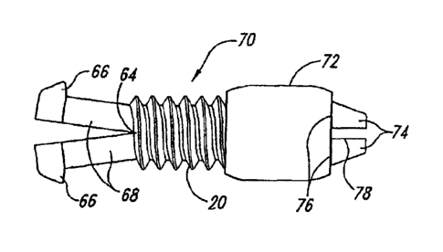
Figures 16 A-G, show, according to one exemplary embodiment of the present
invention,
a slide-collar clamping line-stop member. The line-stop member 10 comprises a
generally
elongated line-clamping member 60 having a length and outer surface and having
a longitudinal
or axial bore suitable for operative passage of a line, and an engagement
collar 72 (e.g.,
cylindrical collar) having a collar channel therethrough for receiving (e.g.,
reversibly receiving)
the line-clamping member, and slidably positionable along the line-clamping
member 60, and
suitable and positionable to reversibly hold the line-clamping means 68 (e.g.,
line-clamping
arms 68) of the line-clamping member 60 in a line-clamping position to engage,
during
operation of the line stop member, a line p, and suitable and positionable to
reversibly disengage
the line-clamping means 68 of the line-clamping member 60 from the line-
clamping position to
reversibly disengage a line. The line-clamping member 60 comprises a
longitudinal axial bore
or channel suitable to allow slidable passage of a line therethrough (see,
e.g., Figure 17H). The
line-clamping member 60 additionally comprises, at one end, a line-clamping or
line retaining
portion, e.g., one or a plurality of line-clamping members or line-clamping
arms 68 (e.g., two or
13
CA 02656522 2008-12-24
WO 2007/150076 PCT/US2007/072057
three such arms) or members, and at least one of the arms or members, or each
arm or member
having a collar-stop member (e.g., flange) 66 at one end thereof, the line-
clamping arms 68 or
members operative with the engagement collar 72, and operatively associated
and positionable
with respect to each other (e.g., by means of at least one hinge or pivot
element 64, etc) to allow
for clamping a line therebetween to engage a line. Preferably, the axial bore
passes through at
least through the collar-mounting and retention portion 62 (see Figure 16G) of
the line clamping
member 60, and may extend somewhat into but not necessarily through the
lengths of the line-
clamping arms. The line clamping arms are preferably flat on their surface or
at least a majority
of their surface, or substantially flat on their surface or on a majority
thereof. In particular
embodiments, the portions of the retention arms adjacent to the hinge
position(s)/axial bore
comprise tapered (e.g., half-funnel or half-conical) grooves 82 extending, at
a base diameter of
the taper, from approximately the arm pivot position of line gripping surface
of the arms and
tapering to an apex at the line-gripping surface (see, e.g., the threaded
collar embodiment of
Figure 17H). Such line access tapers 82 in the clamping arms, extend only
partially (e.g., from
about 1% to about 50%, from about 5% to about 45%, about 20%, about 30%, about
40%, etc.)
along the length of the line-gripping surface of the arms, and facilitate
unobstructed introduction
of a line through the line-clamping member 60 and arm base (pivot position)
even when the
arms, in the non-line retention position, are disposed at an acute angle with
respect to each other
(e.g., 15-30 degrees). In other embodiments for retaining larger diameter
lines, ropes, wires,
etc., the line clamping arms may comprise axial line grooves (e.g., half-
circular grooves) on the
entire length of their opposing gripping surfaces to accommodate better
retention of larger lines,
wherein the radius or dimension of the grooves are proportioned to be
correspondingly smaller
than the radius or proportion of the lines to be retained therein, so as to
yet allow for line
retention when the arms are clamped in the line-retention position (and the
surrounding non-
grooved clamping surfaces of the clamping arms are yet engageable and clamped
together). In
particular embodiments, the line stop members are, for example, about 0.5
inches in length, and
the line-clamping arms 68 are about 0.15 inches in length.
Figures 16F, 16G, 17E and 17F show preferred embodiments comprising line-
clamping
arms that are tapered or beveled or ramped to be thicker at their collar stop
member (e.g., flange)
14
CA 02656522 2008-12-24
WO 2007/150076 PCT/US2007/072057
ends. Preferably, although the engagement collar of Figure 16G is shown in an
intermediate
position, for both tapered and untapered arm embodiments the engagement collar
is positioned
near or against the collar stop member 66 when positioned to hold the line-
clamping means 68
(e.g., line-clamping arms 68) of the line-clamping member 60 in a line-
clamping position.
According to preferred embodiments, such tapering (e.g., ramping, beveling,
thickening, etc.)
allows for application of more line pressure when the engagement collar is
positioned in the
engagement position. As will be appreciated by one of ordinary skill in the
art, a variety of
collar and tapered member configurations can be used to customize and provide
for the desired
amount of line pressure, and to accommodate different line diameters. The line
clamping
members may comprise or be of essentially any material (e.g., nylon, plastic,
polypropylene,
metal, rubber, etc), but preferably comprise or are of a material that affords
adequate frictional
gripping and resilience without damaging the line, and many configurations and
materials are
encompassed within the scope of the present invention and will be appreciated
by those of skill
in the art. In particular embodiments, the line-clamping surfaces of the line-
clamping member,
members or arms comprise texturing or other gripping means to enhance line
retention therein or
therebetween. In particular embodiments, such gripping means comprise textured
surfaces,
grooves, ridges, and/or surface protrusions or extensions that conform and are
receivable into
complementary receiving surfaces on the opposing gripping surface or opposing
clamping arm
surface, etc. Additionally gripping materials may also be incorporated into or
onto, or integrated
within, the gripping surfaces or the clamping member, members or arms, etc.
The line-clamping member 60 additionally comprises, at the other end, a collar-
mounting
and retention portion 62, comprising a collar mounting and retention member,
or comprising a
plurality of spaced, resilient collar-mounting and retention arms 74 having a
retention arm
collar-stop flange 76. In particular embodiments, a plurality of resilient
collar-mounting and
retention arms 74 are spaced or separated by at least one slot 78, the slot
suitable to allow for
reversibly decreasing (e.g., by compressing the arms toward each other) the
distance between the
collar-mounting and retention arms, or between a portion thereof, to allow for
initial mounting
and retention (by virtue of the retention arm collar-stop flanges) of the
engagement collar 72 on
the line-clamping member 60. In certain embodiments, and situated
approximately between the
CA 02656522 2008-12-24
WO 2007/150076 PCT/US2007/072057
pair of line-clamping arms 68 and the collar-mounting and retention portion 62
is an
engagement collar positioning portion 20 or member. The engagement collar
positioning
portion 20 comprises means to position the engagement collar 72 at a
particular position or end
the line-clamping member 60. In one aspect, the engagement collar positioning
portion 20
allows for engaging a line by positioning or retaining the engagement collar
72 on the line-
clamping member 60 in a position (e.g., a line-engagement position) that
affords operative
association with the line-clamping arms 68 or member(s) to allow for clamping
a line
therebetween. In another aspect, the engagement collar positioning portion 20
allows for
disengaging a line by positioning or retaining the engagement collar 72 on the
line-clamping
member 60 in a position (e.g., a line-disengagement position) that precludes
operative
association of the engagement collar 72 with the line-clamping arms 8, or
clamping member(s).
In the exemplary embodiment shown, the engagement collar positioning portion
20 comprises a
resilient compressible bulge having, in the uncompressed state, an outside
diameter larger than
the engagement collar channel diameter such that the engagement collar
positioning portion 20
must be compressed (e.g., by applying sufficient force with the engagement
collar) to reposition
the collar between the line-engagement position and the line disengagement
position. It will be
obvious to those of ordinary skill in the art that the engagement collar
positioning portion 20
could alternatively be engageable into a complementary receiving means within
the engagement
collar, and that such complimentary engagement could position or retain the
engagement collar
72 on the line-clamping member 60 in a position (e.g., in a line-engagement,
or a line-
disengagement position) that provides for, or precludes operative association
of the engagement
collar 72 with the line-clamping arms 68, or clamping member(s).
Figures 17A-J, show, according to another exemplary embodiment of the present
invention, a screw-collar clamping line-stop member. The line-stop member
comprises an
elongated line-clamping member 70, and an cylindrical engagement collar 72
having a collar
channel therethrough and positionable along the line-clamping member 70, and
suitable and
positionable to reversibly hold the line-clamping member 70 in a line-clamping
position to
engage a line, and suitable and positionable to reversibly disengage the line-
clamping member
70 from the line-clamping position to reversibly disengage a line. The line-
clamping member 70
16
CA 02656522 2008-12-24
WO 2007/150076 PCT/US2007/072057
comprises a longitudinal axial bore or channel suitable to allow slidable
passage of a line
therethrough. The line-clamping member 70 additionally comprises, at one end,
a line clamping
means, for example, one or a plurality of line-clamping arms 68 or members, at
least one arm or
member having a collar-stop flange 66 at one end thereof, the line-clamping
arms or members
operative with the engagement collar 72, and operatively associated and
positionable with
respect to each other (e.g., by means of at least one hinge or pivot element
64, etc) to allow for
clamping a line, wire, rope, etc., therebetween to engage the line, wire,
rope, etc. Preferably, the
axial bore passes through at least through the collar-mounting and retention
portion 80 (see
Figure 17H) of the line clamping member 70, and may extend somewhat into but
not necessary
through the lengths of the line-clamping arms 68. The line clamping arms are
preferably flat on
their surface or at least a majority of their surface, or substantially flat
on their surface or on a
majority thereof. In particular embodiments, the portions of the retention
arms adjacent to the
hinge position(s)/axial bore comprise tapered (e.g., half-funnel or half-
conical) grooves 82
extending, at a base diameter of the taper, from approximately the arm pivot
position of line
gripping surface of the arms and tapering to an apex at the line-gripping
surface (see, e.g., the
threaded collar embodiment of Figure 17H, Detail B). Such line access tapers
82 in the
clamping arms, preferably extend only partially (e.g., from about 1% to about
50%, from about
5% to about 45%, about 20%, about 30%, about 40%, etc.) along the length of
the line-gripping
surface of the arms, and facilitate unobstructed introduction of a line
through the line-claming
member 70 and arm base (pivot positioned) even when the arms, in the non-line
retention
position, are disposed at an acute angle with respect to each other (e.g., 15-
30 degrees). In other
embodiments for retaining larger diameter lines, ropes, wires, etc., the line
clamping arms may
comprise axial line grooves (e.g., half-circular grooves) on the entire length
of their opposing
gripping surfaces to accommodate better retention of larger lines, wherein the
radius or
dimension of the grooves are proportioned to be correspondingly smaller than
the radius or
proportion of the lines to be retained therein, so as to yet allow for line
retention when the arms
are clamped in the line-retention position (and the surrounding non-grooved
clamping surfaces
of the clamping arms are yet engageable and clamped together). In particular
embodiments, the
17
CA 02656522 2008-12-24
WO 2007/150076 PCT/US2007/072057
line stop members are, for example, about 0.5 inches in length, and the line-
clamping arms 68
are about 0.15 inches in length.
The line-clamping member 70 additionally comprises, at the other end, a collar-
mounting
and retention portion 80, comprising a collar-mounting and retention member,
or a plurality of
spaced, resilient collar-mounting and retention arms 74, at least one such
member or arm having
a retention arm collar-stop flange 76. In particular embodiments, the
plurality of resilient collar-
mounting and retention arms are spaced or separated by at least one slot 78,
the slot suitable to
allow for reversibly decreasing (e.g., by compressing the arms toward each
other) the distance
between the collar-mounting and retention arms to allow for initial mounting
and retention (by
virtue of the retention arm collar-stop flanges) of the engagement collar 72
on the line-clamping
member 70. Situated between the pair of line-clamping arms 68 and the collar-
mounting and
retention portion 80 is an engagement collar positioning portion 20. The
engagement collar
positioning portion 20 comprises means to position the engagement collar 72 on
the line-
clamping member 70. In one aspect, the engagement collar positioning portion
20 allows for
engaging a line by positioning or retaining the engagement collar 72 on the
line-clamping
member 70 in a position (e.g., a line-engagement position) that affords
operative association
with the line-clamping arms 68 or members to allow for clamping a line
therebetween. In
another aspect, the engagement collar positioning portion 20 allows for
disengaging a line by
positioning the engagement collar 72 on the line-clamping member 70 in a
position (e.g., a line-
disengagement position) that precludes operative association with the line-
clamping arms 68. In
the exemplary embodiment shown, the engagement collar positioning portion 20
comprises
thread means complementary to thread receiving means located within the
engagement collar
channel such that the engagement collar positioning portion 20 can be engaged
by threading or
screwing the engagement collar thereon between the line-engagement position
and the line
disengagement position.
In particular embodiments, the engagement collar comprises a texture or
surface pattern
to facilitate gripping and/or turning, positioning or threading the engagement
collar on the line-
clamping member. Figure 17K shows an engagement collar having longitudinal
ridges and/or
18
CA 02656522 2008-12-24
WO 2007/150076 PCT/US2007/072057
grooves on the exterior surface to facilitate gripping and/or turning,
positioning or threading
thereof. The ends of the engagement collar are preferentially beveled or
angled. In particular
embodiments, the engagement collar comprises or consists of a material that is
different than the
material of the line-clamping member with which it interacts or engages. For
example, the line-
clamping member 60 or 70, may comprise or consist of polypropylene, where the
engagement
collar may comprise or consist of metal, polycarbonate, DELRIN (e.g.,
DuPontTM Delrin
acetal polyoxymethylene (POM) resin). In particular embodiments, the collar
comprises or
consists of metal (e.g., lead, steel, iron, etc.) and provides a weight to the
line stop member, and
such weighted embodiments can be used as adjustable line weights for fishing
and other
applications where it is desirable to reversibly and/or adjustably impart a
weight to a line. The
weight of such weights can be varied by varying the length, thickness and/or
material of the
engagement collar.
In particular embodiments, the engagement collar comprises one or more
attachment
members suitable for attaching one or more elements (e.g., lines, spoons 29,
blades, hooks 31,
swivels 33, streamers, etc.) thereto (see, e.g., the engagement collar 72 of
Figure 17F). In
certain embodiments, the engagement collar comprises one or more full loop or
`eye' members,
and/or comprises one or more clip (e.g., clevis clip) members, for attachment
of or more
elements (e.g., lines, spoons 29, blades, hooks 31, swivels 33, and other
elements used in the
fishing or other arts for example) thereto. In this way, the line stop member
can further provide
an attachment means, and can be converted into a lure, attractor member, or
some other function
member via attachment of additional elements to the engagement collar. In
particular
embodiments the engagement collar comprises one or more attached or integral
fins, blades or
propeller surfaces for imparting motion to the line stop member as it travels
through, for
example, water while attached to a fishing line. The engagement collar may be
of a different
color than the line-clamping member to which it is associated. In particular
embodiments, the
line-clamping member is clear and/or translucent, while the engagement collar
is colored and/or
opaque. The engagement collar and/or line-clamping member may be fluorescent,
phosphorescent, or luminescent.
19
CA 02656522 2008-12-24
WO 2007/150076 PCT/US2007/072057
In particular embodiments, the line stop members comprise, in addition to the
engagement collar, an accessory collar 28 that comprises one or more
attachment members
suitable for attaching one or more elements (e.g., lines, spoons 29, blades,
hooks 31, swivels 33,
streamers, etc.) thereto (see, e.g., the accessory collar 28 of Figure 16G,
17F, 17G). In certain
embodiments, the accessory collar 28 comprises one or more full loop or `eye'
members, and/or
comprises one or more clip (e.g., clevis clip) members, for attachment of or
more elements (e.g.,
lines, spoons, blades, hooks, swivels, and other elements used in the fishing
or other arts for
example) thereto. Therefore, either the engagement collar, the accessory
collar, or both may
comprise one or more attachment members suitable for attaching one or more
elements (e.g.,
lines, spoons 29, blades, hooks 31, swivels 33, streamers, etc.) thereto. In
this way, the line stop
member can further provide an attachment means, and can be converted into a
lure, attractor
member, weight element, or some other functional member via attachment of
additional
elements to the accessory collar. In particular embodiments, the accessory
collar comprises one
or more attached or integral fins, blades or propeller surfaces for imparting
motion to the line
stop member as it travels through, for example, water while attached to a
fishing line. The
accessory collar, like the engagement collar, may be of a different color than
the line-clamping
member to which it is associated. In particular embodiments, the line-clamping
member is clear
and/or translucent, while the accessory collar is colored and/or opaque. The
accessory collar,
and/or the engagement collar, and/or the line-clamping member may be colored,
clear,
fluorescent, phosphorescent, or luminescent. In particular embodiments, the
accessory collar
comprises or consists of metal (e.g., lead, steel, iron, etc.) and provides a
weight to the line stop
member, and such weighted embodiments can be used as adjustable line weights
for fishing and
other applications where it is desirable to reversibly and/or adjustably
impart a weight to a line.
The weight of such weights can be varied by varying the length, thickness
and/or material of the
engagement collar.
In particular embodiments (Figure 17G), the accessory collar is slotted (e.g.,
comprises
a'slotted' cylinder) otherwise equipped with line access means (e.g., carbiner
type, or closeable
"C" type means) to provide line access for mounting onto a line for subsequent
engagement of
the accessory collar with a line-stop member that is already mounted on the
line. In this way,
CA 02656522 2008-12-24
WO 2007/150076 PCT/US2007/072057
accessory collars comprising various accessories can be interchangeably,
removeably attached to
and detached from a line-mounted line-stop member so as to provide for
unprecedented
flexibility and adaptability for a variety of needs (e.g., different fishing
accessories) under a
variety of conditions and environments.
In certain embodiments (e.g., fishing embodiments), the accessory collar is
configured so
that it is free to rotate about the longitudinal axis of the line-clamping
member. In other
embodiments, the accessory collar and/or the line-clamping member is
configured with stop
members to partially limit, demarcate or preclude rotation about the axis of
the line-clamping
member. The accessory collars may, for example, be freely rotatable, or may
rotate 45 degrees,
90 degrees, 180 degrees, etc., about the longitudinal axis of the line-
clamping member.
In particular embodiments, lights and or other sensory emitting elements can
be mounted
to the line-stop members and/or to the engagement and/or accessory collars
thereof. In
particular embodiments, the line stop members and/or collars comprise or are
made of
electrically conductive materials. In alternative embodiments, the line stop
members and/or
collars comprise or are made of electrically non-conductive materials.
Particular embodiments
can be used in decorative and/or functional lighting, where flexibility in
color, and/or in another
sensory aspect, and/or position is desired (home lighting, Christmas tree
lighting, holiday
lighting, safety lighting, indoor and outdoor lighting, etc.).
The inventive line stop members are useful for a broad array of applications
in the
fishing and non-fishing arts. The line stop members can be used essentially
anywhere lines,
ropes, wires, ribbons, and the like are used, and where line-related
information, decoration,
functions, attachments, etc., are needed and/or desired, including but not
limited to line
markings, line attachments, and/or decorations in: fencing; construction
sites, framing,
surveying, building, mock-ups, indoor and outdoor lighting, clothes lines,
camping (e.g., tent
lines, pack lines, tether lines, animal tether and/or handing lines and
leashes, etc), fresh water
marine lines, salt water marine lines (preferably using non-corrosive
materials), games, apparel,
belts, packs, straps, connecting lines, etc.
21
CA 02656522 2008-12-24
WO 2007/150076 PCT/US2007/072057
In particular embodiments the line stop member comprises a leveling means
(e.g, bubble
level, electronic level, laser levels, sonic levels, or the like).
In particular embodiments, the line stop members comprise a target (e.g.,
shooting or
archery target, etc.) attached, for example, to the attachment members of the
engagement and/or
accessory collar.
In particular embodiments, the line stop members comprise a signage (e.g.,
notices,
advertisements, warnings, designations, labels, directional indicators, etc)
attached, for example,
to the attachment members of the engagement and/or accessory collar.
According to preferred aspects of the present invention, the inventive line-
stop members
can be used as part of a system, in combination with disengagable strike
indicators as described
herein in detail. Moreover, while the above-described inventive line-stop
members can be
designed in essentially any size to accommodate a variety of line types and
diameters, in
preferred aspects, the inventive line-stop members are designed to be
dimensionally compatible
for engagement within the axial bores (axial channels) of the disengagable
strike indicators
described in detail herein.
Disengagable Strike Indicator:
With reference to FIGURES 1, 2, 5A, 513, 6A-6G, 10A, 10B, 11A, 11B, 12A and
12B,
13A-E, 14 and 15A and B, particular embodiments of the present invention are
directed to a
disengagable strike indicator 28 for a fishing line, comprising a buoyant main
body portion 16
having an exterior surface 14, first and second main body ends, and an axial
channel 10
therebetween, with corresponding first and second main body end surface
openings 8, the
channel 10 sufficient to accommodate slidable passage of a fishing line 2
therethrough. The
main body 16 additionally comprises an exterior line retaining member seat
(e.g., groove,
channel, raised ridge, etc.), which in this embodiment is a groove 6, having
sides and a bottom,
within and around the exterior surface 14, wherein, in this embodiment, the
groove 6
encompasses the channel 10 axis such that the first and second end surface
openings 8 are
disposed on opposite sides of the groove 6. In alternate exemplary embodiments
(see FIGURES
22
CA 02656522 2008-12-24
WO 2007/150076 PCT/US2007/072057
10A and 11A), the line retaining member seat comprises an elevation or ridge 7
(e.g., rounded or
inverted "V"-shaped) protruding, at least to some extent, from the main body
surface 14. In
particular less preferred alternate embodiments (see FIGURES 12A and 12B), the
line retaining
member seat (e.g., groove, channel, raised ridge, etc.) is disposed around the
exterior surface 14,
but does not encompass the channel 10 axis, such that the first and second end
surface openings
8 are disposed on the same side of the retaining member seat (e.g., groove 6).
Embodiments as
shown in FIGURES 12A and 12B are less preferred, because, inter alia (and
absent additional
retentions means), the retaining member 4 is not retained on the line after
disengagement (see
below). The exemplary disengagable strike indicator 28 of FIGURES 1 and 2
further comprises
a resilient (e.g.: elastic; pliant; supple; flexible, etc.) line retention
member 4 having a suitable
shape (e.g., annular) and size so as to be reversibly receivable and
retainable by the line
retaining member seat (e.g., within the groove 6, or upon the ridge 7 (see
FIGURES 10A, 10B,
11A and 11B), and operative with the seat to sufficiently retain a fishing
line 2 passing
therebetween at two points. In particular embodiments of the exemplary strike
indicator 28 (see
FIGURES 1 and 2), the main body channel 10 axis intersects a plane defined by
the retention
member seat (e.g., the exterior groove 6) at a right angle. In preferred
embodiments, however,
the main body channel 10 axis intersects a plane defined by the annular
retention member seat
(e.g., the exterior groove 6) at an acute angle (i.e., less than ninety
degrees). Preferably, the
angle between the main body channel 10 axis at one or the other main body end
8, and a plane
defined by the retention member seat (e.g., the exterior groove 6) is selected
from the range
group consisting of: 180 degrees to 0 degrees, 90 degrees to 0 degrees, 45
degrees to 0 degrees
less than about 90 degrees and greater than about 1 degree, less than about 90
degrees and
greater than about 2 degrees, less than about 45 degrees and greater than
about 1 degrees, less
than about 30 degrees and greater than about 2 degrees; less than about 20
degrees and greater
than about 5 degrees; less than about 15 degrees and greater than about 7
degrees, less than
about 29 degrees and greater than about 25 degrees, about 28 degrees, and 28
degrees.
Preferably, the angle between the main body channel 10 axis at one or the
other main body end
8, and a plane defined by the retention member seat (e.g., groove 6) is less
than about 15 degrees
and greater than about 7 degrees. Preferably, the angle between the main body
channel 10 axis
23
CA 02656522 2008-12-24
WO 2007/150076 PCT/US2007/072057
at one or the other main body end 8, and a plane defined by the retention
member seat (e.g.,
groove 6) is less than about 29 degrees and greater than about 27 degrees. In
particular
embodiments, the angles, in opposite directions, between the main body channel
10 axis at the
respective opposite main body ends 8, and a plane defined by the retention
member seat (e.g.,
groove 6) are the same or substantially the same. In alternate embodiments,
the angles, in
opposite directions, between the main body channel 10 axis at the respective
opposite main body
ends 8, and a plane defined by the retention member seat (e.g., groove 6) are
different. In
particular embodiments, the distance, in opposite directions, from the first
and second main
body end surface openings 8 to the retention member seat (e.g., groove 6) is
the same or
substantially the same. In alternate embodiments, the distances, in opposite
directions, from the
first and second main body end surface openings 8 to the retention member seat
(e.g., groove 6)
are different. Preferably, intersection of plane defined by the retention
member seat (e.g.,
groove 6c channel, raised ridge, etc.) by the main body channel 10 axis is at
a position
corresponding to the center of the main body channel.
In alternate less preferred embodiments (see FIGURES 12A and 12B), the main
body
channel 10 axis does not intersect a plane defined by the retention member
seat (e.g., the exterior
groove 6 or ridge 7, etc.). In particular embodiments, the resilient annular
line retention member
4 protrudes, at least to some extent, beyond exterior surface 14.
In embodiments where the resilient line retention member 4 is receivable into
a groove 6
or channel, the retention member 4 is preferably receivable into the groove 6
to a distance not
greater than about one-half the radial width of the resilient member 4, so
that at least about half
of the member 4 protrudes above the surface 14. However, according to aspects
of the present
invention, the extent of receipt of the retention member 4 into the groove 6
may vary, so long as
the retention member 4 is sufficiently and reversibly retainable. In preferred
embodiments, the
depth of the retention member seat is in the range of about 0.025 cm to about
0.127 cm (e.g.,
0.01 to about 0.05 inches), about 0.038 cm to about 0.10 cm (e.g., 0.015 to
about 0.04 inches),
about 0.05 cm to about 0.076 cm (e.g., 0.02 to about 0.03 inches). Preferably,
the depth of the
24
CA 02656522 2008-12-24
WO 2007/150076 PCT/US2007/072057
retention member seat is in the range of about 0.043 cm to about 0.086 cm
(e.g., 0.017 to about
0.034 inches).
In particularly preferred embodiments (see FIGURES 13A-E and 14), the depth of
the
retention member seat (e.g., groove, channel, raised ridge, etc.) is greater
at or near the main
body ends than at or near the main body sides (central side areas).
Preferably, in such
embodiments, the depth of the retention member seat is greater at or near the
main body ends
and tapers to a lesser depth at or near the main body sides (i.e., central
side areas; corresponding
to a position at or near the center of the main body channel). In particularly
preferred
embodiments, the depth of the retention member seat at or near the main body
ends tapers to a
lesser depth at or near the main body sides (central side areas), with the
depth at or near the main
body ends being twice, or about twice, the seat depth at or near the main body
sides (central side
areas). For example, in particular embodiments, the seat depth at or near the
main body ends is
about 0.086 cm (e.g., about 0.034 inches), and tapers to a depth at or near
the main body sides
(central side areas) of about 0.043 cm (e.g., about 0.017 inches). Without
being bound by
theory, it is believed that upon application of sufficient line tension, the
retention member is first
disengaged from the retention member seat portions at or near the ends of the
main body, and
that further disengagement of the retention member from the main body side
portions of the
retention member seat is advantageously propagated or facilitated by such
tapered-depth
retention seats to provide for a more efficient full disengagement of the
retention member. Such
retention member seat depth tapering can, for example, be continuous tapering,
discontinuous
tapering, stepped tapering, combinations thereof, etc, with the advantage
being afforded by a
method of decreasing the effective retention member seat depth in going from
the main body
ends to the main body central portions. In embodiments with retention member
seats that are
raised ridges or the like, the height of the retention member seat (e.g.,
ridge), the advantage can
be afforded by decreasing the effective retention member seat height in going
from the main
body ends to the main body central portions. Preferable, in such embodiments,
the depth of the
complementary retention member aspect (e.g., the depth of a complementary
retention member
groove that conforms to a raised ridge retention member seat) tapers in
conformity with the
tapered height of the retention member seat (e.g., ridge).
CA 02656522 2008-12-24
WO 2007/150076 PCT/US2007/072057
In particular embodiments, the depth (or height in, e.g., raised ridge
embodiments) of the
retention seat at or near the main body ends is about one-half the thickness
or diameter of the
material comprising the retention member, and tapers to a depth (or height in,
e. g., raised ridge
embodiments) at or near the main body sides (central side areas) of about one-
quarter the
thickness or diameter of the material comprising the retention member.
In embodiments where the resilient line retention member 4 is receivable onto
a ridge 7
(e.g., FIGURES 10A, lOB, 11A and 11B), the retention member 4 is preferably
receivable onto
the ridge 7 to a distance not greater than about one-half the radial width of
the resilient member
4, so that at least about half of the member 4 protrudes above the top of the
ridge 7. However,
according to aspects of the present invention, the extent of receipt of the
retention member 4
onto the ridge 7 may vary, so long as the retention member is sufficiently and
reversibly
retainable upon the ridge 7. FIGURES 10B and 11B show blow-up cross-sectional
views of
exemplary retention member 4 sections to illustrate that. in these elevated
seat or `ridge'
embodiments, the inner surfaces of the retention members provides a
complementary aspect that
conform to the respective exemplary retention member seats (e.g., rounded and
inverted "V"-
shaped ridges, respectively). In particular embodiments, the resilient line
retention member 4 is
elastic or stretchable, and of a size and dimension such that it is
stretchably received and
retained within the groove 6. In preferred embodiments, the line retention
member 4 is annular
(e.g., in the form of an o-ring) or equivalent rubber ring, or resilient ring
of another elastic
material (e.g., plastic, etc.). In particular embodiments, the retention
member seat (e.g., groove
6 or ridge 7) is continuous around the exterior surface 14. In alternative
embodiments, the
retention member seat (e.g., exterior groove 6, or ridge 7) is formed of a
plurality of
discontinuous seat elements (e.g., repeated finite groove or ridge elements or
sections)
appropriately disposed around the exterior surface 14 to form a discontinuous
seat pattern
sufficient to receive and retain the resilient retention member 4. In
preferred embodiments (e.g.,
FIGURES 1, 2, 4, 5A, 513, 10A, 11A, 12A and 12B) the main body 16 is generally
ovoid or
ellipsoid, and the retention member seat is a generally elliptical or annular
groove 6. However,
according to alternate aspects of the present invention, the main body 16, may
assume a variety
of shapes (e.g., FIGURES 6A-6G) and dimensions. The inventive design allows
for essentially
26
CA 02656522 2008-12-24
WO 2007/150076 PCT/US2007/072057
any size of main body 16, and the retention member 4 and corresponding seat
(e.g., 6 or 7) may
assume a variety of sizes, widths, depths, etc., depending on the desired
size, shape or design of
the indicator main body 16. While essentially any main body size could be
made, in preferred
aspects for particular fishing situations, the main body 16 length or diameter
is from about 0.6
cm to about 7.6 cm (e.g., 1/4 to about 3 inches), from about 1.3 cm to about
5.1 cm (e.g., 1/2 to
about 2 inches), from about 0.9 cm to about 3.75 cm (e.g., 7/8 to about 1.5
inches), or from
about 2.8 cm to about 0.64 cm (e.g., 9/8 to about 1.25 inches), depending upon
the type of
application. In preferred aspects the main body length is about 2.7 cm (e.g.,
about 1 1/16
inches), 2.22 cm (e.g., about 7/8 inches), about 1.74 cm (e.g., about 11/16
inches) and 1.27 cm
(e.g., about 0.5 inches), with respective main body widths of about 1.86 cm
(e.g., about 0.734
inches), 1.55 cm (e.g., about 0.61 inches), about 1.25 cm (e.g., about 0.49
inches) and 0.99 cm
(e.g., about 0.39 inches).
Preferably, and preferably for all embodiments, while the main body portion 16
is
buoyant and may be of any suitable material and/or shape, the surface of the
main body portion,
and particularly that part of the surface adjacent to the retention member
seat surface (e.g., at the
retention member seat edge or shoulder), is preferably sufficiently rigid
(e.g., sufficiently non-
deformable or non-compressible) such that during strike-mediated
disengagement, the `moment
arm' of leverage, provided by the orientation and position of the edge of the
retention member
seat with respect to the strike-tensioned line 2 in disengaging the retention
member 4, is not lost,
decreased or compromised because of compression or deformation of the edge of
the retention
member seat.
In particular aspects, corresponding retention members 4 are of a dimension to
be
receivable and retainable within or upon the conforming retention member seats
(e.g., 6 or 7) of
such preferred main body 16 size ranges (e.g., from about 0.6 cm to about 7.6
cm (e.g., from
about 1/4 to about 3 inches) in diameter, etc.). Retention member seat (e.g.,
6 or 7) design and
dimensions reflect the size and shape of the main body 16 and the retention
members 4, and
sufficiently conform to the retention members 4, so as to operationally
reversibly receive and
retain the retention members 4. Such seats (e.g., 6 or 7) can be grooves 6,
channels or slots, etc.,
27
CA 02656522 2008-12-24
WO 2007/150076 PCT/US2007/072057
within the main body bodies 16, or can be elevated surfaces or ridges 7
protruding from the
main body surface 14, and preferably conform in design and dimension to the
main bodies 16
and the retention members 4. Preferred widths (e.g., cross-sectional) for
retention members 4
are those that conform to that of the retention member seats. In preferred
aspects, retention
member cross-sectional widths range from about 0.08 cm to about 0.64 cm (e.g.,
about 1/32 to
about 1/4 inches), etc. In particular aspects the retention members consist,
or are comprised of
elastic, stretchable, resilient material. The dimensions and/or compositions
and/or elasticity
parameters of such resilient retention members are selected to provide
suitable line retention
strengths for different types of fishing and fishing situations. Commercially
available `O-rings'
are a preferred type of resilient annular retention member 4. However a
variety of resilient
materials could be used (e.g., rubber washers, elastic bands, rubber bands,
etc.), or any material
or any structure (resilient or not) that could be reversibly seated and
unseated to reversibly retain
a line 2 thereunder in operative association with the retention member seat.
Preferably, the line-
contact surface of the retention member is of a material that sufficiently
grips the line (e.g.,
rubber, soft plastic, etc.) to preclude line slippage while the main body is
engaged on a line. The
retention members 4 may have a variety of cross-sectional widths and shapes
(e.g., circular,
ovoid, octagonal, square, rectangular, triangular, etc.), provided that they
are reversibly
receivable and retainable into or onto the retention member seat (e.g., 6 or
7). Preferable, the
retaining member 4 sufficiently conforms in shape to the retention member seat
(e.g., 6 or 7) to
provide for adequate retention of the line in the retention member seat when
the main body is
engaged on a line.
In particular embodiments, the line retention member 4 is selected to have
sufficient
retentive force (offers sufficient resistance to being disengaged from the
seat) when engaged
within or upon the line retention member seat (e.g., 6 or 7), so as to
effectively provide for a
`non-strike-disengageable' strike indicator (i.e., wherein the line is held
sufficient tightly
between the retention member and seat so that fish strikes and fish `hook-ups'
do not disengage
the retention member 4 and indicator 28. Moreover, such `fixed' line position
embodiments are
highly useful for particular types of fishing (where a strike-disengageable
and/or slidable
indicator is not needed), and are nonetheless novel and surprisingly effective
by virtue of the
28
CA 02656522 2008-12-24
WO 2007/150076 PCT/US2007/072057
instant inventive line-retention means, which nonetheless makes the indictors
easily adjustable
along a line, and reusable.
In additional aspects, the strike indicator 28, further comprises a fishing
line 2 extending
through the main body channel 10, the line being reversibly attached to the
main body 16 at two
points along the line 2 by means of the exterior retaining member seat (e.g.,
groove 6 or ridge 7)
and the retention member 4, wherein the strike indicator 28 is disengagable
from the line 2 upon
application of sufficient tension to the line 2 (across the two attachment
points) and is thereafter
slidable (e.g., freely slidable) along the line 2. Therefore, in particular
embodiments, the strike
indicator 28, further comprises a fishing line extending through the main body
channel 10, and,
after emerging at the two opposing end openings 8, passing therefrom in, e.g.,
opposing
directions between the retention member 4 and the retention member seat (e.g.,
passing between
the retention member 4 and the external groove 6, or passing between the
retention member 4
and the external ridge 7), wherein the strike indicator 28 is thereby
reversibly attached at two
points along the line 2. The strike indicator 28 is thereby disengagable from
the line 2 upon
application of sufficient tension to the line 2 (to disengage the retention
member 4 from the
retention member seat) and is thereafter slidable along the line 2 (see, e.g.,
FIGURES 5A and
5B).
FIGURE 2 shows the exemplary disengagable strike indicator embodiment 28 of
FIGURE 1, wherein the resilient annular line retention member 4 is seated in
the exterior groove
6 to retain an exemplary fishing line 2 passing therebetween at two points
within the groove 6
(e.g., in this embodiment, positions near and offset from the respective
channel end openings 8).
In particular embodiments, the resilient retention member 4 is, upon
application of sufficient line
tension, preferentially displaced onto the line on the rod-proximal (e.g.,
larger), side of the main
body 16 (e.g., on the side of the larger aspect of the ovoid main body 16 as
in shown in
FIGURES 1, 513, 10A, 11A), which facilitates retention of the line retention
member 4 on the
rod-proximal (hook-distal) side of the strike indicator 28 after disengagement
thereof from the
line 2. Alternately, the resilient retention member 4 is displacable on the
side of the smaller or
opposite aspect of the main body 16. According to particular aspects, the
shape of the indicator
29
CA 02656522 2008-12-24
WO 2007/150076 PCT/US2007/072057
main body 16 and the disposition of the retention member seat (e.g., 6 or 7)
thereto, can be
selected to facilitate displacement of the line retention member to one side
or another of the
indicator main body upon disengagement (see e.g., FIGURES 1, 5B, 10A, 11A and
6B). In
either case, the line retention member 4 is retained around the line 2, and
thus operationally
retrievable for reuse.
In other aspects, the retention member can be constructed, or torsionally-
loaded so as to
predispose disengagement to one side or another of the indicator main body
upon
disengagement. In preferred embodiments (e.g., in particular, with annular,
elastic retention
members), the design and/or manner of attaching the indicator main body
portion to the line
using the line retention member provides for disengaging (upon application of
sufficient line
tension) the retention member to the rod-proximal side of the indicator body.
Preferably, and
with reference to FIGURES 4, 5A and 5B for example, to insure that the
retention member 4
disengages to the rod-proximal side of a line-mounted main body 14 (as shown
in FIGURES 4,
5A and 5B), the retention member (e.g., O-ring) 4 is `torsionally-loaded' by
first engaging and
retaining (e.g., by applying pressure using a finger or thumb) one portion of
the retention
member 4, and the line 2, to be stationary in the hook-proximal area/end of
the line retention
member seat 6 of the main body 14 (e.g., in the hook-proximal (left side of
FIGURE 4) end
groove area of the retention member seat 6), and then `rolling' the non-
engaged diametrically
opposed portion of the retention member 4 along the surface of the main body
14 (e.g., in a
direction from left to right along the upper surface of the main body 14 of
FIGURE 4 for
example) to engage and retain the rolled retention member 4 portion and line 2
into the hook-
distal portion (right side of FIGURE 4) of the line retention member seat 6 of
the main body 14
to provide for a torsionally-loaded retained retention member 4 within the
retention member seat
6, wherein the line retention member 4 is torsionally-loaded within the line
retention member
seat 6 by virtue of the retained rolling. The rolling or torsional loading is
retained within the
seat 6 because, in preferred aspects, the retention member 4 is elastic and
sized in its unstretched
(unstressed) and unrolled annular diameter to be sufficiently smaller than the
corresponding
retention member seat 6, such that the retention member 4 must be stressed
(stretched) (with or
without such rolling) to be retained within the retention member seat 6,
resulting in a `strained'
CA 02656522 2008-12-24
WO 2007/150076 PCT/US2007/072057
(deformed) seated retention member 4 that is held seated within the retention
member by virtue
of the `strain' (elastic, resiliant) forces. Preferably, in the case of
asymmetric main bodies 14
(e.g., ovoid, etc) the smaller end of the indicator main body portion 14 is
oriented in the hook-
proximal orientation (left in FIGURES 4, 5A and 5B), so that the retention
member 4 is first
retained within the retention member seat 6 at the small main body end, and
then rolled along
the surface side of the main body 14 and retained in the retention member seat
at the larger main
body end (right in FIGURES 4, 5A and 5B), to provide for a torsionally-loaded
retention
member 4.
Without being bound by theory it is believed that in such preferred
embodiments,
initially retaining a portion of, for example, a circular retention member 4
(and the line 2) to be
stationary within the hook-proximal area of the retention member seat 6,
followed by rolling a
diametrically opposed portion of the retention member 4 along the main body
surface toward the
hook-distal end of the main body portion 14, and engaging the rolled retention
member 4 (and
the line 2) therein, provides for a torsionally-loaded retention member 4,
wherein the torsional
forces (rolled windings) are asymmetrically distributed toward the rod-
proximal portions of the
retention member 4 and corresponding seat portions. This asymmetrical
torsional distribution is
believed to facilitate or predispose disengagement (upon application of
sufficient line tension) of
the retention member 4 to the rod-proximal side of the line-mounted main body
portion 14 (as
shown in FIGURE 5B). Without being bound by theory, it is believed that the
asymmetrical
torsional distribution decreases the elasticity (or increases the stiffness or
modulus of elasticity;
e.g., increased Young's modulus) of the retention member 4 in the torsionally-
loaded rod-
proximal portion of the retention member 4 relative to the hook-proximal
portion thereof. With
reference to FIGURE 5A, upon application of sufficient line-tension,
therefore, the relatively
elastic hook-proximal portion of the retention member 4 is disengaged from the
retention
member seat firs, or more easily, and is subsequently and vigorously drawn
around the hook-
proximal end of the main body 14 and toward the rod-proximal end of the main
body 14 as the
torsional loading of rod-proximal portion of the retention member 4 (which,
during application
of such sufficient force, remains engaged in the retention member seat 6 for a
longer time
relative to the hook-proximal portion thereof) is relieved.
31
CA 02656522 2008-12-24
WO 2007/150076 PCT/US2007/072057
Essentially, therefore, it is believed that such asymmetric torsional loading
allows for
initial disengagement (from the retention member seat) of the relatively
elastic hook-proximal
portion of the asymmetrically torsionally-loaded retention member 4 first,
whereupon the
retention member `springs' to the rod-proximal side of the main body 14 in
relief of the
asymmetric torsional loading.
Alternatively, according to further aspects of the present invention, an
asymmetric
modulus of elasticity or torsional-loading distribution may be created in the
construction (e.g.,
materials, methods) and/or design of the retention member per se (e.g., to
obviate the need for
`rolling' or the like to asymmetrically increase the modulus of elasticity).
However, rolled,
torsionally-loaded embodiments are preferred, because they provide asymmetric
torsional
loading without the requirement for complex retention member design and/or
materials, while
nonetheless providing for an efficient, controlled strike-activated
disengagement of the retention
member from its seat.
FIGURES 13A-E show a particularly preferred embodiment of a disengagable
strike
indicator 28 for a fishing line, comprising a buoyant ovoid main body portion
16 having an
exterior surface 14, first and second main body ends, and an axial channel 10
therebetween, with
corresponding first and second main body end surface openings 8, the channel
10 sufficient to
accommodate slidable passage of a fishing line 2 (not shown) therethrough. The
main body 16
(e.g., the surface thereof) additionally comprises a line retention member
seat 6 (e.g., groove,
channel, raised ridge, etc.), which in this embodiment is an annular groove 6,
having sides and a
bottom, within and around the exterior surface 14, wherein, in this
embodiment, a plane defined
by the groove 6 intersects the channel 10 axis such that the first and second
end surface openings
8 are disposed on opposite sides of the groove 6 (or of the plane defined
thereby). In this
exemplary embodiment, the main body channel 10 axis intersects a plane defined
by the annular
retention member seat (e.g., the exterior groove 6) at an acute angle of about
28 degrees
(FIGURE 13 D). Additionally, in this exemplary embodiment, the preferred point
of
intersection of the main body channel axis with the plane defined by the
annular retention
member seat is at a position corresponding to the center of the main body
channel (FIGURE 13
D). FIGURE 13B shows exemplary dimensional variables (see TABLE 1 below) for
the main
32
CA 02656522 2008-12-24
WO 2007/150076 PCT/US2007/072057
body length ("A"), width ("B"), axial channel inner bore diameter ("C"), axial
channel outer
bore (countersink) diameter ("D"), countersink depth ("E"), and retention seat
radius ("R4").
FIGURE 14D additionally shows exemplary radius values (radii) for main body
surface portions
("R1," "R2" and R3"). Exemplary values for "A," "B," "C," "D," "E," "R1,"
"R2," "R3" and
"R4" are provided in TABLE 1 below:
TABLE 1. Exemplary values, with respect to FIGURES 13A-E, for "A," `B," "C,"
"D," "E,"
"R1," "R2," "R3" and "R4"
Exemplary A B C D E Rl R2 R3 R4
Embodiment
2.7 cm 1.86 cm 0.295 cm 0.381 cm 0.572 cm 0.60 2.21 0.91 0.203
1 (1 1/16 (0.734 (0.116 (0.15 (0.225 cm cm cm cm
inches) inches) inches) inches) inches) (0.236 (0.87 (0.36 (0.08
inches) inches) inches) inches)
2.22 cm 1.55 cm 0.295 cm 0.381 cm 0.572 cm 0.51 1.83 0.762 0.203
2 (0.61 (0.116 (0.15 (0.225 cm cm cm cm
(7/8 inches) inches) inches) inches) (0.2 (0.72
(0.3 (0.08
inches) inches) inches) inches) inches)
1.74 cm 1.25 cm 0.295 cm 0.381 cm 0.572 cm 0.41 1.47 0.61 0.203
3 (11/16 (0.49 (0.116 (0.15 (0.225 cm cm cm cm
inches) inches) inches) inches) inches) (0.16 (0.58 (0.24 (0.08
inches) inches) inches) inches)
1.27 cm 0.99 cm 0.295 cm 0.381 cm 0.572 cm 0.33 1.17 0.48 0.203
4 (0.5 (0.39 (0.116 (0.15 (0.225 cm cm cm cm
inches) inches) inches) inches) inches) (0.13 (0.46 (0.19 (0.08
inches) inches) inches) inches)
Offset Axis Channel Embodiments
Preferably, the axis of the channel 10 of the main body portion 16 is
coincident with the
true central axis of the main body portion 16 (see, e.g., FIGURE 1).
Alternately, however, the
33
CA 02656522 2008-12-24
WO 2007/150076 PCT/US2007/072057
axis of the channel 10 of the main body portion 16 is offset (e.g., at one or
both channel ends)
and/or is at a different angle with respect to the true central axis of the
main body portion 16.
For example, FIGURES 15A and 15B show an alternate, `off-set' bore embodiment
of a
disengagable strike indicator 28 for a fishing line. In the embodiment of
FIGURES 15A and B,
the axis of the channel 10 of the main body portion 16 is offset from the true
center axis at the
small aspect end of the ovoid main body portion 16 and also is at a different
angle with respect
to the true central axis of the main body portion 16. In such embodiments
where the actual
channel bore is offset from theoretical true main body center axis (cross-
hairs in FIGURE 15B),
e.g., in this embodiment, at the small end of the ovoid (but not at the big
end), during strike-
mediated disengagement of the line retention member 4, the strike-mediated
line tension
continues to be applied to the line retention member 4 at the small end, even
after the point
where the line retention member 4 has reached theoretical true center axis
(cross-hairs). Without
being bound by theory, this offset feature, and particularly when used in
combination with the
asymmetric torsional loading of the line retention member 4 as described
elsewhere herein,
facilitates consistent, reproducible strike-mediated disengagement of the line
retention member 4
to the rod-proximal side of the main body portion 16.
Disengagable Strike Indicator System:
With reference to FIGURES 3, 4, 5A, 513, 7, 12A and 12B, additional aspects
provide a
disengagable strike indicator system for a fishing line 2 and/or leader or
tippet, comprising in
addition to the elements and variations of the novel disengagable strike
indicator described
above, at least one line stop member 18 attachable (e.g., by crimping,
adhering, elastic tension,
etc.) at a user-selectable fixed position to a fishing line 2 and/or leader or
tippet, the line stop
member 18 having an outer surface, first and second stop member ends, and an
axial stop
member channel therebetween, with corresponding first and second stop member
end surface
openings, wherein the line stop member 18 is receivable into the axial channel
10 of the main
body 16, and wherein an aspect of the shape and/or dimension (e.g., flange, or
enlarged or
extended aspect, etc.) of the line stop member 18 is operative to engage the
line stop member 18
when received into the main body channel 10, and is thereby sufficient to
preclude travel of a
34
CA 02656522 2008-12-24
WO 2007/150076 PCT/US2007/072057
disengaged strike indicator beyond a user-selected fixed position where it
engages the stop
member 18. Such stop members 18 can be of any suitable material (e.g., metal,
plastic, elastic
material, etc.), and are dimensionally configured so as to be readily
passable, upon line retrieval,
through line guides of a fishing rod. Preferably, the outer surfaces of such
stop members 18 are
non-gripping to facilitate separation from the indicator main body channel 10
upon
disengagement of the strike indicator 28 from the line 2, and to facilitate
unfettered passage
through the line guides upon line retrieval past the user-selected position of
stop member 18
attachment.
In this embodiment (e.g., FIGURE 4), an inventive strike indicator 28 is shown
attached
to the line 2 at a point where it is engaged with a stop member 18, which has
been attached to
line 2 at a user-selected position. In particular embodiments, the distance
between the stop
member 18 ends is less than one-half the distance between the main body ends
8. In additional
preferred embodiments, the disengagable strike indicator system comprises two
line stop
members 18 receivable at opposite ends of the main body 16. Therefore,
additional
embodiments provide a disengageable strike indicator system (having at least
one stop member
18), further comprising a fishing line 2 extending through the main body
channel 10 and
reversibly attached to the main body at two points along the line 2 by means
of the exterior
retention member seat (e.g., groove 6) and retention member 4, wherein the
strike indicator is
disengagable from the line 2 upon application of sufficient tension to the
line 2, and is thereafter
slidable from or to the attachment position of the at least one line stop
member 18. Therefore, in
particular embodiments, the strike indicator 28, comprises a fishing line 2
extending through the
main body channel 10 and, after emerging at the two opposing main body channel
end openings
8, passing therefrom in opposing directions under the retention member 4
within the external
seat (e.g., groove 6), wherein the strike indicator is thereby reversibly
attached at two points
along the line 2, disengagable from the line 2 upon application of sufficient
tension to the line 2,
and is thereafter slidable to or from the user-selected attachment position of
the at least one line
stop member 18.
CA 02656522 2008-12-24
WO 2007/150076 PCT/US2007/072057
FIGURES 3A. 3B and 3C show side views of three exemplary line stop members 18
attachable to a fishing line 2 at a user-selectable position. The inventive
line stop member(s) 18
are receivable into the axial channel 10 of the main body of the inventive
disengagable strike
indicators (partially shown as dashed lines 14 in the figure) to provide for a
disengagable strike
indicator system, and the shape and/or dimension of the line stop members 18
is operative to
engage the line stop member 18 within the main body channel 10 of the
inventive strike
indicators to limit slidable travel of the disengaged strike indicator along a
fishing line 2. The
engagement aspect of the stop member may, for example, correspond to an
enlarged portion
thereof (e.g., flange, bulge, etc.) that engages a conforming stop member
receiving surface of the
axial channel 10 (see FIGURES 3A-3C). The line stop members can be of any
material that is
fixable to the line 2 (e.g., a ductile material that can be pressed, clamped
or crimped to be
retainable at a fixed point on a line 2 and/or leader or tippet, an elastic
member that attaches by
means of its inherent dimensional character and elasticity, etc.). Affixing
the line stop member
to the line may be by any suitable means including but non limited to,
crimping of a stop
member comprising a ductile material (e.g., metal, plastic, etc.), clamping of
a clampable stop
member, adhering of a stop member to the line, affixing by inherent elastic
means, etc., as long
as the stop member is attached to the line in a fixed or effectively fixed,
non-slidable (or at least
substantially non-slidable) manner, so that the attached stop members serves
to effectively
preclude slidable travel of the disengaged strike indicator beyond the stop
member attachment
position. Stop members, may comprise, e.g., on the inner surface thereof,
material or structures
that preclude or minimize line wear, or materials or structures that
facilitate gripping of the line.
Encompassed within the scope of the present invention are those stop members
that are attached
to a line in a manner sufficient, in practical terms depending on the type and
nature of the
operational fishing, to substantially preclude slidable movement, but
nonetheless are
positionable along the line with sufficient applied force if repositioning is
desired (e.g., tight
fitting elastic members for example). Preferably, the stop members are of a
ductile metal, and
have a non-gripping exterior surface so as not to preclude travel through line
guides.
36
CA 02656522 2008-12-24
WO 2007/150076 PCT/US2007/072057
FIGURE 4 shows a side view of an exemplary disengagable strike indicator
system
embodiment having a line stop member 18 engaged therein, so that in operation
the strike
indicator is engaged at a user-selected position along the line and/or leader
or tippet.
FIGURES 5A and 5B show a side view of an exemplary disengagable strike
indicator
system embodiment having a line stop member 18 engaged therein, and further
shows (in going
from FIGURE 5A to 5B) how the annular line retention member 4 is displaceable
from the
retention member seat (e.g., exterior groove 6) of the main body 16 upon
application of
sufficient line tension, which in turn disengages the strike indicator,
thereafter allowing sliding
of the disengaged strike indicator along the line 2. Typically, in such
embodiments, the
retention member is displaced on the larger aspect side of the main body
(e.g., ovoid), but
alternatively, displacement can be on the opposing side of the strike
indicator. According to
particular aspects, the shape of the indicator main body 16 and the
disposition of the retention
member seat (e.g., 6 or 7) thereto, can be selected to facilitate displacement
of the line retention
member to one side or another of the indicator main body upon disengagement
(see e.g.,
FIGURES 1, 4, 513, 10A, I IA and 6B). In either case, the line retention
member 4 is retained
around the line 2, and thus operationally retrievable for reuse in the novel
disengaging strike
indicator system.
Significantly, therefore, the novel, nature, design and methods using the
present strike
indicators and systems allow for adjustable, consistent (e.g., repeatedly
disengagable at the
same, or substantially the same line tension value), controlled and
reproducible disengagement
and reuse in the absence of significant wear, degradation, deformation, etc.,
of the attachment
surfaces and of the line surfaces. Moreover, the inventive strike indicators
and systems may be
selected to disengage at variety of line tension values, depending upon the
conformation,
dimension and properties (e.g., size, elastic strength (i.e., tensile elastic
modulus), etc.) of the
line retention members 4, conformation and dimension of the line retention
member seats, and
the relational disposition of these aspects with respect to each other and
with respect to other
aspects of the strike indicator (e.g., relative orientation to axial channel
10; orientation with
37
CA 02656522 2008-12-24
WO 2007/150076 PCT/US2007/072057
respect to particular conformational aspects (e.g., asymmetric shape aspects;
see, e.g., FIGURE
6B) of the main body 16, etc.).
In particular embodiments, the disengagable strike indicator system comprises
a first and
a second line stop member 18, and further comprises a fishing line 2 (or
leader and/or tippet)
extending through the main body channel 10 and through a channel of the first
stop member 18
engaged therein, the line 2 being reversibly attached to the main body 16 at
two points along the
line 2 by means of the line retention member seat (e.g., exterior groove 6,
raised ridge 7, etc.)
and retention member 4, wherein the strike indicator is disengagable from the
line 2 upon
application of sufficient tension to the line 2 (e.g., tensional stress along
the line crossing the two
attachment positions) and is thereafter slidable (e.g., from a position of
engagement with the first
stop member, to the engagement and attachment position of the second line stop
member 18 that
is positioned along the line a user selectable distance from the position of
the first attached strike
indicator, and on the side of the strike indicator that is opposite that of
the first engaged line stop
member 18). Therefore, in particular embodiments, the strike indicator 28,
comprises a first and
a second line stop member 18 , further comprises a fishing line 2 extending
through the main
body channel 10 and through a channel of the first line stop member 18 engaged
therein, and the
line 2, after emerging at the two opposing main body channel end openings 8,
passing therefrom
in opposing directions under the retention member 4 seated on the retention
member seat (e.g.,
the external groove 6, raised ridge 7, etc.), wherein the strike indicator is
thereby reversibly
attached (e.g., restrained) at two points along the line 2, disengagable from
the line 2 upon
application of sufficient tension to the line 2 (across the two line
restraining positions) and is
thereafter slidable to the attachment position of the second line stop member
18 positioned along
the line 2 a distance from the attached strike indicator, and on the side of
the strike indicator that
is opposite that of the first engaged line stop member.
The inventive novel system comprises at least one stop member 18, and is not
necessarily limited to any particular disengagable strike indicator design,
provided that it is
freely slidable on the line 2 once disengaged therefrom. Therefore, general
aspects provide a
disengagable strike indicator system for a fishing line, comprising: a fishing
line 2; a buoyant
38
CA 02656522 2008-12-24
WO 2007/150076 PCT/US2007/072057
disegagable strike indicator that is reversibly attachable to, disengagable
from and thereafter
slidable along a fishing line 2; and at least one strike indicator stop member
18 attachable to a
user-selectable position along the fishing line 2, and sufficient, in
operation, to limit slidable
travel of the disengaged strike indicator along the fishing line 2. Particular
general aspects
comprise first and second attachable strike indicator stop members 18 attached
at different user-
selected positions along the fishing line 2, and suitable, in operation of the
system, to delimit a
slidable range of the disengaged slidable strike indicator along the fishing
line. In particular
general aspects, the disengagable strike indicator is attached to the line 2
in engagement with the
first line stop member attached at a first user-selected line position, and,
upon disengagement,
the disengaged strike indicator is thereafter slidable along the fishing line
2 between the first and
second line stop members 18. In preferred aspects, the strike indicator is
disengagable my
means of application of sufficient tension to the fishing line (e.g., upon a
fish `hook-up').
Therefore, general aspects of the present invention provide a method of
fishing using a
disengagable strike indicator system in combination with at least one strike
indicator stop
member 18.
With reference to FIGURES 4, 5A, 5B and 7, specific embodiments provide a
method of
fishing (e.g., essentially any type of fishing in any type of water) with a
strike indicator at a set
depth X (e.g., corresponding to a `holding zone' or `concentration feeding
zone' 22) greater than
the length Y of a fishing rod, comprising: obtaining a fishing line 2 in
operable communication
with a fishing rod 32, the line 2 extending through rod line guides and from a
tip portion of the
fishing rod to a fishing hook 20 and retrievable with line retrieving means
mounted on the
fishing rod 32, the extended line portion having hook-proximal and hook-distal
positions. The
method further comprises attaching, to the extended line portion, a first and
a second strike
indicator stop member 18 at a first, hook-distal line stop position
corresponding to a desired
fishing depth X, and a second, hook-proximal line stop position corresponding
to a position of
length Y from the hook, and equal to about the length Y of the fishing rod,
respectively, wherein
the line stop members 18 are receivable into a buoyant disengagable strike
indicator 28, and
wherein the shape and/or dimensional aspect of the line stop members 18 is
operative to engage
the line stop member 18 within the buoyant disengagable strike indicator 28.
The method
39
CA 02656522 2008-12-24
WO 2007/150076 PCT/US2007/072057
additionally comprises attaching, between the two line stop members 18, to the
line 2 and in
engagement with the first hook-distal stop member 18, a buoyant disegagable
fishing line strike
indicator 28 reversibly attached to, disengagable from and thereafter slidable
along the fishing
line 2 between first and second stop members 18, the strike indicator 28
disengagable by
application of sufficient line tension. The method further comprises:
disengaging the strike
indicator 28 by setting the hook into a fish (e.g., a fish `hook-up'); and
retrieving the extended
line to a line position corresponding to about that of the second stop member
18, wherein fishing
at a depth X greater than the length Y of a fishing rod and yet reaching the
hooked fish for
effective and efficient retrieval is afforded.
Novel Reversibly Disengagable Line-Stop Members and Systems and Methods
Comprising
Same:
Additional aspects provide novel line-stop member devices and methods for
adjustably
and reversibly engaging a line (including, but not limited to fishing lines,
ropes, string, cable,
wire, cords, etc.) at an engagement position and/or for demarcating one or
more positions and/or
spans along a line. The inventive line-stop members are reversibly
disengagable (or reversibly
engagable), and thereby slidably adjustable and positionable along a line, and
two such line-stop
members can be used to define a user-selectable range or span therebetween.
Further aspects provide novel disengagable strike indicator systems that
comprise, in
addition to a strike-disengagable or non-strike-disengagable strike indicator,
at least one
`reversibly disengagable strike indicator line-stop member' (e.g., as
described herein below) that
is attachable at a user-selected fixed position along a fishing line, and is
engagable with the
inventive strike indicator main bodies to limit slidable travel of a
disengaged strike indicator
along the fishing line, or is additionally or alternatively fixedly engageable
with an internal
engagement collar of particular inventive strike indicator embodiments to
provide for a non-
strike-disengagable strike indicator (e.g., an effectively fixed strike
indicator).
In preferred embodiments, particular `dual-use' inventive strike indictor
bodies (having
an internal engagement collar) can be used for dual purposes as a strike-
disengagable (using a
CA 02656522 2008-12-24
WO 2007/150076 PCT/US2007/072057
line-retention member in the line-retention member seat of the strike
indicator main body, and
not fixedly engaging the internal enagagement collar with the inventive
reversibly enagagable
line-stop member), or non-strike-disengagable (not using a line-retention
member, and rather
fixedly engaging the internal enagagement collar with the inventive reversibly
enagagable line-
stop member) strike indicator.
Further aspects provide novel methods for fishing, comprising fishing with an
inventive
strike-disengagable or non- strike-disengagable strike indicator with the
inventive reversibly
disengagable strike indicator line-stop member(s) (e.g., as described herein
below), or the
inventive strike indicator system.
FIGURES 16A-G, show, according to one exemplary embodiment of the present
invention, a novel slide-collar clamping line-stop member. The line-stop
member comprises an
elongated line-clamping member 60, and an cylindrical engagement collar 72
having collar
channel therethrough and slidably positionable along the line-clamping member
60, and suitable
and positionable to reversibly hold the line-clamping member 60 in a line-
clamping position to
engage a line, and suitable and positionable to reversibly disengage the line-
clamping member
60 from the line-clamping position to reversibly disengage a line. The surface
of the collar may
comprise gripping surfaces or texture or be of multi-faceted (e.g.,
triangular, square, hexagonal,
etc.) to provide for better gripping and reversible tightening. The line-
clamping member 60
comprises a longitudinal axial bore 80 or channel suitable to allow slidable
passage of a line
therethrough. The line-clamping member 60 additionally comprises, at one end,
at least one pair
of line-clamping arms 68 or members each having a collar-stop flange 66 at one
end thereof, the
line-clamping arms or members operative with the engagement collar 72, and
operatively
associated and positionable with respect to each other (e.g., by means of at
least one hinge or
pivot element 64, etc) to allow for clamping a line therebetween to engage a
line. The line-
clamping member 60 additionally comprises, at the other end, a collar-mounting
and retention
portion 62, comprising a plurality of spaced, (e.g., resilient) collar-
mounting and retention arms
74, each having a retention arm collar-stop flange 76. In particular
embodiments, the plurality
of collar-mounting and retention arms are spaced or separated by at least one
slot 78, the slot
41
CA 02656522 2008-12-24
WO 2007/150076 PCT/US2007/072057
suitable to allow for reversibly decreasing (e.g., by compressing the arms
toward each other) the
distance between the collar-mounting and retention arms to allow for initial
mounting and
retention (by virtue of the retention arm collar-stop flanges) of the
engagement collar 72 on the
line-clamping member 60. Situated between the pair of line-clamping arms 68
and the collar-
mounting and retention portion 62 is an engagement collar positioning portion
20. The
engagement collar positioning portion 20 comprises means to position the
engagement collar 72
on the line-clamping member 60. In one aspect, the engagement collar
positioning portion 20
allows for engaging a line by positioning the engagement collar 72 on the line-
clamping member
60 in a position (e.g., a line-engagement position) that affords operative
association with the
line-clamping arms 68 or members to allow for clamping a line therebetween. In
another aspect,
the engagement collar positioning portion 20 allows for disengaging a line by
positioning the
engagement collar 72 on the line-clamping member 60 in a position (e.g., a
line-disengagement
position) that precludes operative association with the line-clamping arms 68.
In the exemplary
embodiment shown, the engagement collar positioning portion 20 comprises a
resilient
compressible bulge having, in the uncompressed state, an outside diameter
larger than the
engagement collar channel diameter such that the engagement collar positioning
portion 20 must
be compressed (e.g., by applying sufficient lateral force with the engagement
collar) to
reposition the collar between the line-engagement position and the line
disengagement position.
FIGURES 17A-M, show, according to another exemplary embodiment of the present
invention, a screw-collar clamping line-stop member. The line-stop member
comprises an
elongated line-clamping member 70, and an cylindrical engagement collar 72
having a collar
channel therethrough and positionable along the line-clamping member 70, and
suitable and
positionable to reversibly hold the line-clamping member 70 in a line-clamping
position to
engage a line, and suitable and positionable to reversibly disengage the line-
clamping member
70 from the line-clamping position to reversibly disengage a line. The surface
of the collar may
comprise gripping surfaces or texture or be of multi-faceted (e.g.,
triangular, square, hexagonal,
etc.) to provide for better gripping and reversible tightening. The line-
clamping member 70
comprises a longitudinal axial bore 78 or channel suitable to allow slidable
passage of a line
therethrough. The line-clamping member 70 additionally comprises, at one end,
at least one pair
42
CA 02656522 2008-12-24
WO 2007/150076 PCT/US2007/072057
of line-clamping arms 68 or members each having a collar-stop flange 66 at one
end thereof, the
line-clamping arms or members operative with the engagement collar 72, and
operatively
associated and positionable with respect to each other (e.g., by means of at
least one hinge or
pivot element 64, etc) to allow for clamping a line therebetween to engage a
line. The line-
clamping member 70 additionally comprises, at the other end, a collar-mounting
and retention
portion 62, comprising a plurality of spaced, (e.g., resilient) collar-
mounting and retention arms
74, each having a retention arm collar-stop flange 76. In particular
embodiments, the plurality
of collar-mounting and retention arms are spaced or separated by at least one
slot 78, the slot
suitable to allow for reversibly decreasing (e.g., by compressing the arms
toward each other) the
distance between the collar-mounting and retention arms to allow for initial
mounting and
retention (by virtue of the retention arm collar-stop flanges) of the
engagement collar 72 on the
line-clamping member 70. Situated between the pair of line-clamping arms 68
and the collar-
mounting and retention portion 62 is an engagement collar positioning portion
20. The
engagement collar positioning portion 20 comprises means to position the
engagement collar 72
on the line-clamping member 70. In one aspect, the engagement collar
positioning portion 20
allows for engaging a line by positioning the engagement collar 72 on the line-
clamping member
70 in a position (e.g., a line-engagement position) that affords operative
association with the
line-clamping arms 68 or members to allow for clamping a line therebetween. In
another aspect,
the engagement collar positioning portion 20 allows for disengaging a line by
positioning the
engagement collar 72 on the line-clamping member 70 in a position (e.g., a
line-disengagement
position) that precludes operative association with the line-clamping arms 68.
In the exemplary
embodiment shown, the engagement collar positioning portion 20 comprises
thread means
complementary to thread means located within the engagement collar channel
such that the
engagement collar positioning portion 20 must be engaged by screwing the
engagement collar
thereon between the line-engagement position and the line disengagement
position
According to preferred aspects of the present invention, the inventive line-
stop members
can be used as part of a system, in combination with strike-disengagable (as
described herein in
detail) or non-strike-disengagable strike indicators as described herein below
in detail.
Moreover, while the above-described inventive reversibly disengagable line-
stop members can
43
CA 02656522 2008-12-24
WO 2007/150076 PCT/US2007/072057
be designed in essentially any size to accommodate a variety of line types and
diameters, in
preferred aspects, the inventive line-stop members are designed to be
dimensionally compatible
for engagement within the axial bores (axial channels) of the strike-
disengagable and non-strike-
disengagable strike indicators described in detail herein.
As will be appreciated by one of ordinary skill in the art, the inventive line-
stop members
comprise a line-clamping or line-pinching means in operable association with
an engagement
collar that is slidable between engagement and disengagement positions, and
further comprising
an engagement collar retention portion with one or more retention flanges, and
while the above-
described clamping-arm embodiments illustrate a preferred mode, the line-
clamping arms could
be replaced with other line-clamping means as long as such means are
operatively associated
with the engagement collar to provide for reversible engagement. For example,
as can be
appreciated from Figures 16A and 16B, a deformable (e.g., compressible) bulb
member or the
like can be operative with the collar to provide for line-clamping.
Alternatively, a tapered
member, hinged or otherwise articulated with the line-stop member and
operative with the
engagement collar and receivable (upon positioning the engagement collar in
the engagement
position) into a receiving slot along the line-stop member to provide for
clamping pressure on
the line is encompassed within the present conception.
Novel Reversibly Disengagable Line-stop Members and Non-Strike-Disengagble
Systems and
Methods Comprising Same:
Additional preferred embodiments provide novel slidably adjustable non-strike-
disengagable strike indicators, comprising a reversibly disengagable line-stop
member
embodiment as described above in combination with a buoyant strike indicator
main body
portion having an `internal engagement member' 24 (e.g., collar, flange, band,
ring, notch, etc.)
within the main body channel 10 (see, e.g., FIGURES 18A-C and 19A-C). In
certain of such
preferred aspects, the retention arm collar-stop flange(s) 76 of the collar-
mounting and retention
portion 62 optionally engage an internal engagement member 24 (e.g., collar,
flange, band, ring,
44
CA 02656522 2008-12-24
WO 2007/150076 PCT/US2007/072057
notch, etc.) within the main body channel 10 of particular `dual-use' strike
indicator main body
embodiments.
Such `dual-use' inventive strike indictor bodies (having an internal
engagement collar)
are usable for dual purposes as a strike-disengagable (using a line-retention
member 4 in the
line-retention member seat 6 of the strike indicator main body, and not
fixedly engaging the
internal engagement member 24 (e.g., collar) with the inventive reversibly
engagable line-stop
member), or non-strike-disengagable (not using a line-retention member, and
rather fixedly
engaging the internal enagagement member 24 (e.g., collar) within the channel
10 of the
inventive reversibly enagagable line-stop member) strike indicator.
Alternatively, the inventive
reversibly disengagable line-stop members may be used with strike indicator
embodiments that
do not have a retention member or retention member seat as used herein,
provided that such
main bodies comprise an internal engagement member (e.g., collar) engagable by
the inventive
reversibly engagable (reversibly disengagable) line-stop members.
Figures 18A-C show, for example, a screw-collar clamping line-stop member
(e.g., such
as that of FIGURES 17A-D) in combination with a dual-use strike indicator main
body portion
having an internal engagement collar 24 within the axial channel 10. The line-
stop member
comprises an elongated line-clamping member 70 having line-clamping arms 68 or
members at
one end, and a cylindrical engagement collar 72 having a collar channel
therethrough and
positionable along the line-clamping member 70 and suitable and positionable
to reversibly hold
the line-clamping member 70 in a line-clamping position to engage a line. The
threads may be
flattened (e.g., to reduce or avoid wear or stripping of the threads with
repeated use). The
surface of the collar may comprise gripping surfaces or texture or be of multi-
faceted (e.g.,
triangular, square, hexagonal, etc.) to provide for better gripping and
reversible tightening. The
line-clamping member 70 additionally comprises, e.g., at the other end, a
collar-mounting and
retention portion 62, comprising a plurality of spaced, (e.g., resilient)
collar-mounting and
retention arms 74, each having a retention arm collar-stop flange 76. Figures
18A and 18B
show the combination before and after, respectively, engagement of the screw-
collar clamping
line-stop member (e.g., engagement of the retention arm collar-stop flanges 76
thereof) with the
CA 02656522 2008-12-24
WO 2007/150076 PCT/US2007/072057
internal engagement collar 24. Figures 18C and 19C show, according to further
aspects, an
exemplary tool 82 for disengaging the screw-collar clamping line-stop member
(e.g., for
disengagement of the retention arm collar-stop flanges 76 thereof) from the
internal engagement
collar 24. The tool may have an optional line-slit 29 to accommodate the line,
and thus preclude
pinching or damaging the line, during disengagement of the retention arms 74
from the internal
engagement collar 24. In this exemplary embodiment, the internal engagement
collar 24 and the
counterbores 22 are somewhat asymmetrically configured within the strike
indicator main body.
Figures 19A-C show, according to additional embodiments, the screw-collar
clamping
line-stop member of FIGURES 18A-C, in combination with a strike indicator
having an internal
engagement collar 24 within the axial channel 10. Figures 19A and 19B show the
combination
before and after, respectively, engagement of the screw-collar clamping line-
stop member with
the internal engagement collar 24 (e.g., before and after engagement of the
retention arm collar-
stop flanges 76 thereof). Figure 19C shows, according to further aspects, an
exemplary tool 82
for disengaging the screw-collar clamping line-stop member from the internal
engagement collar
24. In this exemplary embodiment, the internal engagement collar 24 and the
counterbores 22
are significantly asymmetrically configured within the strike indicator main
body.
The disengagement tool 82 can be of any design suitable to displace or
compress the
retention arms 74 and retention arm collar-stop flanges 76 such that they can
be removed
(disengaged) from the internal engagement collar 24. The exemplary tool shown
comprises a
funnel shape having an angle and size suitable to compress the retention arms
74 and retention
arm collar-stop flanges 76 upon application of the tool to the arms within the
channel 10 using
sufficient pressure. The tool, for example could be of a variety of shapes
(e.g., funnel, cylinder,
square, ovoid, rectangular, sizes and/or designs (e.g., compressive shape
(e.g., funnel, cylinder,
etc.), pliar-type arms, etc., and may be either single-ended or double-ended
(as shown herein) or
may have more ends. The tool may have the same or different tool sizes or
designs on each end
thereof. All that is required is that the tool, or some portion thereof can be
applied to the
retention arms 74 and/or retention arm collar-stop flanges 76 to facilitate
disengagement from
the internal engagement collar 24. The tool may have an optional line-slit 29
to accommodate
46
CA 02656522 2008-12-24
WO 2007/150076 PCT/US2007/072057
the line, and thus preclude pinching or damaging the line, during
disengagement of the retention
arms 74 from the internal engagement collar 24.
As will be apparent to one of skill in the relevant art, line stop members
(e.g., any of
those shown herein) can be of any size (e.g., any size that is receivable into
a strike indicator
main body portion). Preferably, the inventive line-stop members are large
enough to facilitate
easy handling, engagement, disengagement, adjustment, etc., by a user.
Additionally, as will be
apparent to one of skill in the relevant art, only one line-stop member (e.g.,
only one reversibly
disengaging line-stop member, or any described herein) is required, according
to aspects of the
instant invention, to affix a strike indicator main body to a line. This is
true regardless of the
particular strike indicator main body used, and in the case of `dual-use'
indicator main body
portions, regardless of whether the strike indicator main body is being used
as a strike-
disengagable strike indicator (i.e., using a line-retention member 4 in the
line-retention member
seat 6 of the strike indicator main body, and not fixedly engaging the
internal engagement
member 24 (e.g., collar) with the inventive reversibly engagable line-stop
member), or as a non-
strike-disengagable strike indicator (i.e., not using a line-retention member
4, and rather fixedly
engaging the internal enagagement member 24 (e.g., collar) within the channel
10 of the
inventive reversibly enagagable line-stop member). Therefore, there is no
requirement that the
attributes of the main body channel 10, such as the depth (or even presence)
of an opposing
(opposite that of the countersink bore used for receiving the initially
positioning line-stop
member) countersink bore 22, and/or the positioning of the internal engagement
member (e.g.,
collar) within the channel 10 must be symmetrical. That is, the counter bores,
if present in a
plurality, may be of different diameters, and/or depths, or there may be only
a single counterbore
22 at one end of the channel 10. Additionally, the position of the internal
engagement member
24 (e.g., collar, flange, band, ring, notch, etc.) may be other than a central
position of the channel
10; that is, the internal engagement member may be disposed closer to, at or
near one or the
other end of the channel 10, for example. Preferably, in small main body
portion embodiments
(such as that shown in FIGURES 19A-C), the internal engagement member 24 is
disposed at or
near the end of the channel 10 that is opposite the end receiving the line-
stop member. In this
way, the size of the line stop-member can be kept sufficiently large to
facilitate easy handling by
47
CA 02656522 2008-12-24
WO 2007/150076 PCT/US2007/072057
a user, while at the same time enabling use of very small strike indicator
main bodies. Thus,
while preferred embodiments of the inventive strike indicator main bodies have
a channel 10 and
at least one counterbore 22 at one end, there is no requirement for an
opposing counterbore, and
even if such an opposing counterbore is present, there is no requirement that
the diameter and/or
depth of such opposing counterbore is the same as that of the opposed
counterbore. In certain
`system' embodiments described herein comprising two stop members (e.g., a rod-
proximal
line-stop member, and a hook-proximal line-stop member), where a main body is
slidable
therebetween, all that is really required is that the line-stope members
(e.g., the hook-proximal
line-stop member) be able to engage, and/or limit slidable travel of the main
body portion with
respect to the line attachment position of the line-stop member.
Modular Accessory Attachment Member Embodiments:
In particular embodiments, as described in detail herein above, the inventive
line-stop
members are insertable, attachable, engageable, etc., with and/or into a
strike indicator or other
buoyant flotation member to provide for a strike indicator system, and method
of using same.
In additional embodiments, the inventive line-stop members are insertable,
attachable,
engageable, etc., with and/or into other objects or elements that are desired
to be operatively or
spatially associated with the line via the line-stop member. For example, in
certain
embodiments, the surface of the engagement collar, or other accessible surface
of the line-stop
member, comprises at least one attachment means (e.g., at least one hook,
loop, eye, snap, pin,
clasp swivel, clevis clip, etc) to provide for attaching one or more
additional objects (e.g., line,
swivel member, blade member, weight or sinker, float member, etc.) to the line-
stop member. In
particular line-stop member embodiments (see, e.g., Figure 16G), the
attachment means
comprises an accessory collar 28 that attaches to the line stop member (e.g.,
to the `collar
mounting and retention portion,' as defined herein, of the line-stop member).
Preferably the
accessory collar 28 is rotatably attached to the line-stop member so that the
collar (and anything
attached to the attachment means of the collar) is free to rotate about the
line-stop member (e.g.,
48
CA 02656522 2008-12-24
WO 2007/150076 PCT/US2007/072057
about the longitudinal axis thereof). The accessory collar 28 comprises at
least one attachment
means (e.g., 26 or 27) on its surface (e.g., at least one hook, loop, eye,
snap, pin, clasp swivel,
clevis clip, etc) to provide for attaching one or more additional objects
(e.g., line, swivel
member, blade member, weight or sinker, float member, etc.) to the line-stop
member. The
inventive line-stop members, therefore, not only have utility for engaging
and/or demarcating
one or more positions and/or spans along a line, rope, etc., and for attaching
to strike indicators,
but also have substantial utility for attaching to essentially anything that
is desired to be brought
in operable and/or spatial association with a line, rope, etc.
49