Note: Descriptions are shown in the official language in which they were submitted.
CA 02656542 2008-12-23
WO 2008/002658 PCT/US2007/015082
ATTY DKT NO: 11450.00001 EXPRESS MAIIL LABEL NO. EV 855911533 US
APPARATUS AND METHODS OF FORMING A CURVED STRUCTURE
Background of the Invention
[0001] This invention relates generally to the field of construction and more
particularly,
but not by way of limitation, to methods and apparatus for forming curved
structures, such
as curved walls, archways, barrel ceilings and round columns.
[0002] Typically, straight wall construction uses a runner attached to the
floor structure
and a corresponding runner attached to the ceiling structure (or free
floating) with studs
positioned between and attached to the runners. The runners and studs form a
structural
frame suitable for supporting gypsum board, such as SHEETROCKTM, or other wall
covering. Construction of other straight line structures relies on these same
principles.
Common construction practices use wooden 2x4's and 2x6's (approximate
dimensions of
boards in inches) to form the runners and studs. However, steel runners and
studs are
gaining acceptance in both commercial construction as well as in residential
construction.
[0003] These standard materials and methods are suitable for a major portion
of most
construction, however, curved structures, such as curved walls, archways,
barrel ceilings
and round columns are frequently desired for their architectural styling.
While the principles
for constructing curved structures are much the same as those for constructing
straight
structures, formation of such structures typically requires significantly more
cuts in the
runners and studs to form the desired radius. As a result, several track
designs formed from
sheet metal have been developed to reduce the amount of labor and waste
associated with
the construction of curved structures. While the sheet metal runners have been
accepted as
improvements over standard construction techniques, many are unwieldy and are
difficult to
position and retain in a desired position.
[0004] Thus, there is a need for improved methods and apparatus of forming a
curved
structure which provide adequate strength, minimal labor requirements, cost
efficiency and
flexibility in application. In particular, there is a need for methods and
apparatus which
may be readily formed and retained in a desired radius.
Summary of the Invention
[0005] The present invention provides improved apparatus and methods of
forming a
curved structure which meet the needs described above.
[0006] The current invention provides an apparatus suitable for constructing
curved walls,
archways and other similar structures. The apparatus of the current invention
comprises a
CA 02656542 2008-12-23
WO 2008/002658 PCT/US2007/015082
2
plurality of sections wherein each section has a base portion with at least
one slot. The
sections are pivotally linked, i.e., joined to one another. As such, the
sections may be
integrally formed or may be formed separately and joined to each other in a
manner known to
those skilled in the art. Each base portion carries at least one upwardly
projecting member.
The upwardly projecting member of one base portion projects through the slot
of an adjacent
base portion. Bending or compressing the upwardly projecting member against
the base
portion precludes further pivotal movement between the adjacent sections.
[0007] In another embodiment of the current invention, the base portion of
each section has
at least two arcuate slots. Additionally, the sections are pivotally joined in
a manner which
provides a pivot point located between the arcuate slots. Preferably, each
base portion carries
at least one tab projecting through each arcuate slot of an adjacent based
portion.
[0008] In a further embodiment, the current invention provides an apparatus
for
constructing curved structures wherein the apparatus comprises a plurality of
sections with
each section having a base portion carrying an eyelet, an eyelet receiving
hole and at least one
slot. The plurality of sections are pivotally joined to one another by
positioning and pivotally
securing the eyelet of one base portion within the eyelet receiving hole of an
adjacent base
portion. Additionally, each base portion carries at least one tab projecting
through the slot of
an adjacent base portion. Preferably, each base portion carries at least two
arcuate slots and the
pivot point resulting from the assembly of the eyelet with the eyelet
receiving hole is located
between the arcuate slots. Typically, the arcuate slots are generally
concentric with the pivot
point.
[0009] In yet another embodiment, the current invention provides an apparatus
for
constructing curved structures. The apparatus comprises a plurality of
sections wherein each
section has a base portion having at least one serrated slot. The sections of
the apparatus are
pivotally joined to one another. Additionally, the base portion of each
section carries a
deformable protrusion extending upward from the base portion. The deformable
protrusion is
positioned on the base portion at a location such that it extends upward
through the serrated
slot of an adjacent base portion. Subsequent deformation of the protrusion
will lock the
adjacent sections in place thereby precluding further pivotal movement between
the adjacent
sections.
[0010] Another embodiment of the current invention provides an apparatus for
constructing
curved structures wherein the apparatus comprises a plurality of sections with
each section
having a base portion. The sections are pivotally joined to one another and
have a pivot point
CA 02656542 2008-12-23
WO 2008/002658 PCT/US2007/015082
3
located between at least two arcuate serrated slots. Preferably, the pivotal
link between
adjacent sections is formed by pivotally securing an eyelet carried by one
base portion in an
eyelet receiving hole carried by an adjacent base portion. The serrated
arcuate slots of each
base portion are associated with at least one protrusion carried by an
adjacent section. The
protrusion extends upwardly from the adjacent base section through the arcuate
serrated slot.
Subsequent deformation of the protrusion precludes pivoting of the adjacent
base sections in
relation to one another.
[0011] Still further, the current invention provides an apparatus for
constructing curved
structures wherein the apparatus comprises a plurality of sections with each
section having a
base portion. Each base portion.has at least two parallel slots and each slot
is associated with a
protrusion or upward extending tab carried by an adjacent section. Each slot
has a width
sufficient to permit pivotal movement of adjacent sections when the tab or
protrusion is
positioned with the slot. Preferably, each of section of the apparatus has a
base portion, a first
track portion and a second track portion, the track portions being oppositely
positioned and
generally parallel such that the track portions and the base portion form a
channel.
[0012] Additionally, the current invention provides an apparatus for
constructing curved
structures wherein the pivotal connection of the apparatus provides the
ability to "lock in" a
desired radius. In this embodiment, the apparatus comprises a plurality of
sections, each
section having a base portion which carries an eyelet and an eyelet receiving
hole. The eyelet
receiving hole has a serrated configuration. The sections are pivotally joined
to one another
when the eyelet of one base portion is positioned and pivotally secured within
the eyelet
receiving hole of an adjacent base portion. Compression of the eyelet against
the serrated edge
of the eyelet receiving hole precludes further pivotal movement of adjacent
sections.
[0013] In anotlier embodiment wherein the pivotal connection provides the
ability to "lock
in" a desired radius, the apparatus of the current invention comprises a
plurality of sections
with each section having a base portion carrying an eyelet and an eyelet
receiving hole. In this
instance, the eyelet receiving hole has at least two tabs defined by radial
cuts. Every other tab
defined by the cuts is folded up from the base portion. The plurality of
sections are pivotally
joined to one another when an eyelet of one base portion is positioned and
pivotally secured
within an eyelet receiving hole of an adjacent base portion. Following
positioning at a desired
radius, the apparatus is locked into place by compressing the upward folded
tabs of the eyelet
receiving hole against the eyelet to preclude further pivotal movement of the
adjacent section.
CA 02656542 2008-12-23
WO 2008/002658 PCT/US2007/015082
4
[0014] In yet another embodiment, the current invention provides an apparatus
for forming
a curved structure wherein the apparatus comprises integrally joined sections.
In the preferred
embodiment, the apparatus is prepared from a single piece of construction
material. In one
preferred embodiment, the integral connection provides a pivotal connection
located between
track portions forming one side of the apparatus. In another embodiment, the
pivotal
connection is centrally located on the base portion of the apparatus.
[0015] Still further, the current invention provides a method for fixing the
shape of a
curved structure. The method of the current invention comprises the steps of
providing an
apparatus having a plurality of pivotally connected sections, each section
having a base
portion, at least one slot and at least one upwardly projecting member
protruding from the base
portion through a slot of an adjacent base portion. The apparatus is
positioned in a desired
radius and the projecting tab is struck with sufficient force to compress the
member against the
base portion thereby restricting further pivotal movement of the adjacent
sections.
[0016] It is therefore a general object of the present invention to provide
improved
apparatus and methods of forming a curved structure. Other and further
objects, features and
advantages of the present invention will be readily apparent to those skilled
in the art upon a
reading of the following disclosure when taken in conjunction with the
accompanying
drawings.
Brief Description of the Drawings
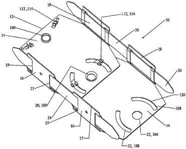
[0017] FIG. 1 is a perspective view of one embodiment of the current invention
depicting
tabs protruding through arcuate slots.
[0018] FIG. 2 is an alternative embodiment of the device depicted in FIG. 1
wherein
compressible protrusions extend through arcuate slots having serrations.
[0019] FIG. 3 depicts a close-up view of the protrusion in relation to a
serrated edge of an
arcuate slot.
[0020] FIGS. 4 and 6 depict further embodiments of the current invention
wherein each
FIG. depicts a modified eyelet arrangement which provides the ability to
pivotally position
and subsequently lock adjacent sections.
[0021] FIGS. 5 and 7 each depict a close-up view of the modified eyelet of
FIGS. 4 and 6
respectively.
[0022] FIG. 8 depicts an altemative embodiment of the current invention
wherein the
pivot point or pivotal connection is offset from the center of the section.
CA 02656542 2008-12-23
WO 2008/002658 PCT/US2007/015082
100231 FIG. 9 depicts an alternative embodiment of the current invention
wherein slots
and tabs provide a slidable pivot and provide subsequent locking of adjacent
sections.
[0024] FIG. 10 depicts an alternative embodiment of the current invention
wherein
adjacent sections pivot in relation to one another using slots and tabs and
wherein the
sections are integrally formed and joined by a pivotal connection.
[0025] FIGS. 11 and 12 depict a modified pivotal connection wherein an eyelet
receiving
hole has a serrated configuration.
[0026] FIG. 13 depicts an alternate embodiment of FIG. 1 wherein the base
portions are
integrally formed and connected.
[0027] FIG. 14 provides another embodiment of the apparatus of FIG. 1, wherein
the
strap portion has been replaced by an integral extension carried by each track
portion.
[0028] FIG. 15 is a partially sectioned view of a curved wall formed using the
apparatus
of the present invention.
[0029] FIGS. 16-17 depict an alternative embodiment of the current invention
wherein
the base portion carries outwardly projecting tongues with one tongue having a
foldable
portion.
[0030] FIGS. 18-19 depict an alternative embodiment of the current invention
wherein
the base portion carries outwardly projecting tongues with each tongue having
a foldable
portion.
[0031] FIGS. 20-22 depict an alternative embodiment of the current invention
having a
centrally located tongue carried by one end of the base portion of a section
while the
opposite end of the base portion includes a slot.
Detailed Description of the Preferred Embodiments
[0032] Referring to the drawings, presently preferred embodiments of the
invention and
their operation are illustrated. Like reference numerals refer to like parts
throughout the
drawings and this description.
[0033] Referring to FIG. 1, a presently preferred embodiment of the present
invention is
illustrated and generally designated by the numeral 10. Apparatus 10 is
comprised of a
plurality of pivotally connected sections 12. Due to its sectional structure,
apparatus 10 can
be constructed of virtually any length to fit the desired application.
Although the
embodiment of FIG. 1 is depicted with discrete sectional components, the
current invention
also contemplates integrally formed and connected sections 12 as depicted in
FIGS. 10 and
13.
CA 02656542 2008-12-23
WO 2008/002658 PCT/US2007/015082
6
[0034] In a preferred embodiment, each section 12 has a base portion 14, a
first track
portion 16 and a second track portion 18. Optional first and second track
portions 16, 18 are
oppositely positioned near the perimeter of base portion 14. First track
portion 16 is oriented
generally parallel to second track portion 18. Track portions 16, 18 are
oriented generally
perpendicular to base portion 14.
[0035] Track portions 16, 18 comprise proximate edge 15, which is proximate
to' base
portion 14 and which is formed at the junction of base portion 14 and track
portion 16, 18.
Track portions 16 further comprise distal edge 17, which is distal in relation
to base portion
14. Track portions 16, 18 also comprise first end 19 and second end 21, which
are
oppositely spaced on the length of track portions 16, 18.
[0036] In the preferred embodiments, adjacent sections 12 are pivotal in
relation to each
other. Preferably, adjacent sections are pivotally joined together by a
pivotal connection 20.
Pivotal connection 20 may be a screw, rivet, pop rivet, brad or other fastener
disposed
through a hole 22 in base portion 14 of a section 12 and through a hole 22 in
base portion 14
in an adjacent section 12. Additionally, the current invention contemplates a
pivotal
connection which is integrally formed with sections 12. For example see, FIG.
10 wherein
pivotal connection 20 integrally joins adjacent sections 12. Additionally, see
FIG. 13,
wherein pivotal connection 20 is an integral portion of adjacent base portions
14.
[0037] In the example of FIG. 1, each base portion 14 carries an eyelet 100
and an eyelet
receiving hole 104. As known to those skilled in the art, by properly securing
eyelet 100
within eyelet receiving hole 104 a pivotal connection 20 is formed which
permits pivotal
movement of adjacent sections in relation to one another. Pivotal connections
20 of this
type are advantageous due to the ease and cost efficiency of manufacturing.
[0038] As illustrated for example in FIGS. 1, 2, 4, 6, 11-13 and 14, adjacent
sections 12
are preferably pivotally connected by pivotal connections 20. Pivotal
connections 20 are
generally centrally located substantially equidistant between the sides of
each section 12,
i.e., between first track portion 16 and second track portion 18 in a
preferred embodiment.
[0039] In the preferred embodiment, apparatus 10 includes strap members 24, 26
which
are adapted for slidably engaging track portions 16, 18 of sections 12. The
combination of
track portions 16, 18 and strap members 24, 26 are only one of many designs
suitable for
defining a channel for receiving wooden, metal or other suitable studs.
[0040] Sections 12 move on pivotal connection 20 to form the desired radius of
curvature
or a variable curve. In a preferred embodiment, apparatus 10 also has a second
strap
CA 02656542 2008-12-23
WO 2008/002658 PCT/US2007/015082
7
member 26 which is adapted for slidably engaging second track portion 18. When
one
section 12 is pivoted relative an adjacent section 12, strap members 24, 26
slide relative
track portions 16, 18 of a section 12. Those skilled in the art will recognize
that strap
members 24, 26 may be replaced by integral flange 30 carried by each track
portion 16 and
18. As shown in FIG. 14, flange 30 extends from track portions 16 and 18 of
each section
12 in a manner sufficient to overlap and preferably contact track portions 16
and 18 of the
next adjacent section. More preferably, as shown in FIG. 14, flange 30 engages
integrally
formed slots 34.
[0041] The present invention also provides novel configurations for fixing
apparatus 10
in a desired position. In the embodiment depicted in FIG. 1, arcuate slots 108
are generally
concentric with pivotal connection 20. Preferably, slots 108 are equidistance
from pivotal
connection 20. Typically, each section 12 carries two arcuate slots and at
least one
deformable upwardly projecting member 112. In this embodiment, upwardly
projecting
member is a tab 114 which extends outward from base portion 14. One skilled in
the art
will recognize that in certain configurations of the current invention member
112 or tab 114
may project downward or sideways; however, for simplicity, this disclosure
will treat
member, tab 112, 114 as projecting upwards. Typically, tab 114 will be formed
by
stamping. Preferably, each section carries at least two tabs 114 and more
preferably each
section carries four tabs 114. Each section carries tabs 114 on the end
opposite of arcuate
slots 108. Thus, when assembled, tabs 114 project upwards through slots 108.
Following
positioning of apparatus 10 in the desired position, tabs 114 are hammered or
otherwise
compressed against base portion 14 to lock adjacent sections 12 in position
relative to one
another.
[0042] Although FIG. 1 depicts each base portion with two arcuate slots 108,
one skilled
in the art will recognize that a single arcuate slot 108 will suffice.
Further, in the current
invention, it is preferred to utilize a metal or other construction material
including plastics
having a sufficient degree of softness to permit deformation or shearing of
the base portion
14 when tabs 114 are compressed against base portion 14. Thus, compression of
tabs 114
against base portion 14 will preferably deform base portion 14 in the
configuration of tab
114 to physically lock adjacent sections 12 in a position relative to one
another.
[0043] FIGS. 2 and 3 depict an alternative embodiment of the current
invention. As in
FIG. 1, this embodiment of the current invention utilizes at least one and
preferably two
CA 02656542 2008-12-23
WO 2008/002658 PCT/US2007/015082
8
arcuate slots 108. Also, as in FIG. 1, this embodiment utilizes a pivotal
connection 20
formed by securing eyelet 100 within eyelet receiving hole 104.
[0044] The embodiment of FIG. 2 differs from the embodiment of FIG. 1 in that
upwardly projecting member 112 is a protrusion 116. Protrusion 116 may be
formed by any
method known to those skilled in the art. Preferably, protrusion 116 is formed
by stretching
an area of base portion 14 by stamping or other process. At least one and
preferably two
protrusions 116 are carried by base portion 14 at the opposite end of base
portion from
arcuate slots 108. Thus, when assembled, protrusions 116 project upwards
through slots
108. Following positioning of apparatus 10 in the desired position,
protrusions 116 are
compressed or swaged to force the expansion of protrusions 116. Once expanded,
protrusion 116 engages the sidewalls 120 of slots 108 to preclude further
movement of
adjacent sections. In the preferred embodiment depicted in FIG. 2, at least
one area of
sidewalls 120 carries a serrated edge 124. A close-up view of serrated edge
124 is provided
by FIG. 3. Serrated edge 124 provides a mechanical locking surface which is
engaged by
compressed protrusion 116, thereby enhancing the locking capabilities of
compressed
protrusion 116.
[0045] FIG. 13 depicts an alteinative pivotal connection 20 suitable for use
in the current
invention. As depicted in FIG. 13, sections 12 are integrally formed.
Typically, a sheet
metal stamping process will be used to form apparatus 10. In the embodiment
depicted in
FIG. 13, pivotal connection 20 is formed by compressing the integral pivotal
connection
144 between adjacent sections 12. Following compression, pivotal connection 20
flexes
sufficiently to permit pivotal movement between base portions 14. As discussed
above,
following positioning of apparatus 10, tabs 114 or other upwardly projecting
member 112
(not shown) are compressed against base portion 14 to preclude further pivotal
movement of
sections 12. Thus, this embodiment of the current invention demonstrates the
ability to
form apparatus 10 from a single piece of construction material.
[0046] In another embodiment of the current invention, pivotal connection 20
provides
both pivoting and locking capabilities for apparatus 10. FIGS. 4 and 5 depict
one
arrangement of pivotal connection 20 operating in this manner. While apparatus
10
depicted in FIGS. 4 and 5 also includes track portions 16, 18 and straps 24
and 26, as noted
above, other arrangements of apparatus 10 including elimination of one or both
track
portions 16, 18 will be apparent to one skilled in the art.
CA 02656542 2008-12-23
WO 2008/002658 PCT/US2007/015082
9
[0047] In the embodiment of FIGS. 4-7 and 11-12, pivotal connection 20 is
preferably a
modified eyelet arrangement. As shown in FIG. 4, eyelet receiving hole 104 is
characterized by segments 128 and 132. Segments 128 and 132 are initially
defined by
radial cuts in eyelet receiving hole 104. Eyelet receiving hole 104 and
segments 128 and
132 are typically formed by stamping or punching processes known to those
skilled in the
art.
[0048] In the preferred embodiment, at least two segments are formed. More
preferably,
four segments are formed. As depicted, the most preferred embodiment utilizes
six
symmetrical segments, three each of segments 128 and 132. Segments 128 are
bent
upwards while segments 132 remain in their original position to define the
diameter of
eyelet receiving hole 104.
[0049] As depicted in FIG. 4, each base portion 14 carries eyelet receiving
hole 104 and
eyelet 100 at opposite ends of base portion 14. When initially assembled,
eyelet 100 is
placed within eyelet receiving hole 104 and swaged or rolled in a manner
sufficient to join
sections 12 while permitting pivotal movement of adjacent sections 12.
[0050] With reference to FIG. 5, during assembly segments 128 are preferably
folded
over swaged eyelet 100 in a manner which permits continued pivotal movement of
adjacent
sections. Following position of apparatus 10 in the desired configuration,
segments 128 are
compressed against eyelet 100 sufficiently to preclude further pivotal
movement between
adjacent sections 12. Compression of segments 128 may be carried out by
crimping,
hammering or other technique known to those skilled in the art. Preferably,
the
compression method applies sufficient force to segments 128 to subsequently
produce
deformation of eyelet 100 into gaps 134 defined by segments 132. Thus,
deformed eyelet
100 mechanically locks adjacent sections 12 together.
[0051] An alternative embodiment of the invention depicted in FIGS. 4 and 5 is
provided
by FIGS. 6 and 7. In this embodiment of the current invention pivotal
connection 20 is a
modified eyelet arrangement. In this instance eyelet receiving hole 104 has
been modified
by initially forming segments 128 and 132; however, in this instance, segments
132 have
been removed from eyelet receiving hole 104. Additionally, segments 128 have
been folded
upwards and backwards to provide an additional layer above base portion 14.
Thus,
modified eyelet receiving hole 104 has a serrated configuration suitable for
enhancing
mechanical locking of apparatus 10 in a desired position. In this embodiment
of the current
invention, eyelet 100 extends upwardly from base portion 14 a sufficient
distance to permit
CA 02656542 2008-12-23
WO 2008/002658 PCT/US2007/015082
conventional swaging, rolling or other suitable technique of eyelet 100 within
eyelet
receiving hole 104 to produce pivotal connection 20. Following initial
assembly of
apparatus 10, eyelet 100 is swaged or rolled as discussed above to permit
pivotal movement
between adjacent sections 12. Once apparatus 10 has been positioned in a
desired
configuration, eyelet 100 may be further crimped or otherwise compressed
against segments
128, thereby securing apparatus 10 in the desired configuration. Preferably,
the crimping
force applied to eyelet 100 is sufficient to deform eyelet 100 by compressing
eyelet 100 into
gaps 136 defined by segments 128. Thus, this embodiment of the current
invention locks
apparatus 10 in the desired configuration by frictional pressure of eyelet 100
against
segments 128 and by deformationally locking eyelet 100 in gaps 136.
[0052] The embodiments depicted in FIGS. 11-12 utilize a modified eyelet
receiving hole
104 to enhance the mechanical locking of adjacent sections. As depicted in
FIGS. 11-12
eyelet receiving hole 104 may be formed in a variety of geometric patterns.
Although
generally circular, these patterns provide a tooth liked arrangement which
includes gaps
136. Following assembly of each section, eyelets 100 are swaged or otherwise
deformed in
a manner suitable to secure one section 12 to another while permitting pivotal
movement of
adjacent sections. Following positioning in a desired arrangement, eyelet 100
is further
compressed to preclude further pivotal movement. Preferably, sufficient
compressive force
is applied to deform eyelet 100 into gaps 136 thereby creating a locking
arrangement
between eyelet 100 and eyelet receiving hole 104.
[0053] While the embodiments of FIGS 4-7 and 11-12 have been depicted with
pivotal
connection 20 centrally located between tracks 16 and 18, one skilled in the
art will
recognize that pivotal connection 20 may be offset to either side of base
portion 14. For
example, in another embodiment of the current invention depicted in FIG. 8,
pivotal
connection 20 is positioned off center of the central location depicted in
FIGS. 1-7. In the
embodiment of FIG. 8, base portion 14 carries eyelet receiving hole 104 and
eyelet 100 on
opposite ends thereof. Additionally, base portion 14 carries at least one tab
and preferably
two tabs 114. On the opposite end of tabs 114 is a slot 140. When apparatus 10
is
assembled, tabs 114 are received within slot 140.
[0054] In the embodiment depicted in FIG. 8, slot 140 is a straight slot;
however, slot 140
has a width sufficient to permit pivotal movement of adjacent sections 12 on
pivotal
connection 20. Additionally, a single arcuate slot 108 may be used as depicted
for example
in FIG. 10 in the embodiment of FIG. 8. When using straight slot 140, tabs 114
are
CA 02656542 2008-12-23
WO 2008/002658 PCT/US2007/015082
11
preferably of a length sufficient to permit both tabs to engage base portion
14 when
compressed to lock apparatus 10 in the desired configuration. However,
engagement of
only one tab 114 with base portion 14 will provide satisfactory locking
capabilities.
Additionally, although riot depicted in FIG. 8, one skilled in the art will
recognize that the
modified eyelet configurations described in conjunction with FIGS. 4-7 will
also be useful
in the embodiment of FIG. 8 with or without slots 140 and 108.
[0055] A simplified version of the current invention is provided in FIGS. 9
and 10. In the
embodiments of FIGS. 9 and 10, single or dual straight line slots 140 or
arcuate slots 108
are carried on one end of base portion 14. On the opposite end of base portion
14, at least
one tab 114, more preferably paired tabs 114 or protrusions (not shown) are
provided.
When apparatus 10 is assembled, tabs 114 project upwards through at least one
slot 140,
more preferably two slots 140 or arcuate slots 108. In the embodiment of FIG.
9, slots 140
have a width sufficient to permit pivotal movement between adjacent sections
12. Further,
tabs 114 of FIG. 9 have a length sufficient to permit engagement of base
portion 14
following formation of the desired radius of curvature. Thus, each tab 114,
when
compressed, precludes further pivotal movement of adjacent sections 114.
Following
arrangement of apparatus 10 in the desired configuration, at least one tab 114
is compressed
against base portion 14. Tab 114 may be compressed against base portion 14 by
any
conventional method known to those skilled in the art. For example, when
constructing a
curved wall, tab 114 may be struck with a hammer thereby compressing tab 114
against
base portion 14.
[0056] FIG. 10 also depicts an altemative embodiment of pivotal connection 20.
In the
embodiment of FIG. 10, pivotal connection 20 is a bendable or flexible
integrally formed
connection 148. Thus, this embodiment of the current invention demonstrates
the ability to
form apparatus 10 from a single piece of construction material.
[0057] While the embodiments of FIGS. 9 and 10 depict slot 140 a distance from
the
center of base portion 14, a single slot 140 may be conveniently located
centrally between
track portions 16, 18. Finally, in the embodiments of FIGS. 9 and 10, tabs 114
are slightly
splayed apart following initial assembly of apparatus 10. Thus, prior to
compression, tabs
114 in cooperation with slots 140 or 108 may act as pivotal connection 20.
[0058] FIG. 15 illustrates a curved structure formed using the method and
apparatus of
the present invention. Apparatus 10 provides a first runner 42 and a second
runner 44. First
runner 42 and second runner 44 are oppositely placed as shown in FIG. 15.
Runners 42, 44
CA 02656542 2008-12-23
WO 2008/002658 PCT/US2007/015082
12
are placed in the desired curved position and the radius of curvature of each
runner can be
fixed or locked as previously discussed herein. Track portions 16, 18 of first
runner 42 are
substantially aligned with track portions 16, 18 of second runner 44. Runners
42 and 44 can
be attached to building structure, i.e., as shown in FIG. 15, first runner 42
is attached to
floor structure and second runner 44 is attached to ceiling structure. Runners
42, 44 can be
attached to building structure for example by driving nails or fasteners
through base portion
14 of sections 12. The present invention will also provide good results when
used to
construct a curved "floating" wall, i.e., a wall in which runner 44 is not
attached to ceiling
or other building structure.
[0059] Studs 46 are attached between first runner 42 and second runner 44.
Studs 46 may
be attached, for example, by nails disposed through track portions 16, 18,
through strap
members 24, 26 and into studs 46. Studs 46 can be formed of wood or metal or
other
appropriate materials.
[0060] Once studs 46 have been attached to runners 42, 44, wall covering or
gypsum
board 48, such as SHEETROCKTm, is attached to studs 46 using, for example,
self-tapping
dry-wall screws or nails.
[0061] Structures other than curved walls can be formed using the same method.
For
example, a column structure (not shown) can be formed by positioning the first
runner in a
circle attached to the floor structure, a second runner in a circle attached
to the ceiling
structure, studs attached between runners 42, 44 and gypsum board 48 attached
to studs 46.
Curved archways and barrel ceilings can be similarly constructed.
[0062] Figures 16 and 17 depict a further embodiment of the current invention.
In this
embodiment, base portion 14 carries an outwardly projecting tongue 152 at one
end 153 and
an additional tongue 154 at the opposite end 155. Tongue 152 includes a
foldable portion
157 carries at least one slot 32. As shown in Fig. 16, foldable portion 157 is
provided by
cutting a portion of tongue 152 along line 158. Tongue 154 on the opposing end
of base
portion 14 has at least one and preferably two upwardly projecting members 112
stamped
therein. In the preferred embodiment, tongue 154 may have a degree of
flexibility but does
not have a foldable portion. Preferably, slot 32 is an arcuate slot 108. As
depicted in Figs.
16 and 17 assembly of apparatus 10 entails positioning tongue 152 adjacent to
tongue 154,
bending foldable portion 157 under or over tongue 154 such that upwardly
projecting
members 112 align with arcuate slot 108. Upwardly projecting members 112 pass
through
arcuate slot 108 and permit rotational or pivotal movement of adjacent base
portions 14.
CA 02656542 2008-12-23
WO 2008/002658 PCT/US2007/015082
13
Following positioning in the desired arc, upwardly projecting members 112 are
deformed
against base portion 14 thereby securing apparatus 10 in the desired
configuration. One
skilled in the art will recognize that slot 108 may be carried by the opposite
tongue 154
while upwardly projecting members 112 may be carried by foldable portion 157.
[0063] Figures 18 and 19 depict another embodiment which is similar to the
embodiment
of Fig. 16. In Figure 18, tongue 154 also includes a foldable portion 159.
Foldable portion
159 carries at least one and preferably two upwardly projecting members 112
stamped
therein. Preferably slot 32 is an arcuate slot 108. Assembly of the embodiment
depicted in
Fig. 18 entails folding portion 157 up and over tongue 154 and subsequently
folding portion
159 up and over portion 157 such that upwardly projecting members 112 are
received
within slot 32 or arcuate slot 108. The order of folding is not critical.
Prior to securing
upwardly projecting members 112 against foldable portion 157, adjacent base
portions 14
are pivotal in relation to one another. Following positioning in the desired
arc, upwardly
projecting members 112 are deformed thereby securing apparatus 10 in the
desired
configuration. One skilled in the art will recognize that slot 108 and
upwardly projecting
members may be carried by the opposite tongues discussed herein.
[0064] Figures 20, 21 and 22 depict yet another alternative embodiment of the
current
invention. In this embodiment each base portion 14 carries at least one slot
32 and at least
one tongue 162. Preferably, slot 32 is an arcuate slot 108. Tongue 162 may be
integrally
formed with base portion 14 projecting outward from end 163 thereof as
depicted in Fig. 20.
More preferably, as depicted in Figs. 21 and 22, tongue 162 is provided by
cutting and
folding a portion of base portion 14 outward from end 163 as shown in Figs. 20
and 21.
Although shown as in a rectangular configuration, tongue 162 may be generally
circular or
any other configuration. Tongue 162 carries at least one upwardly projecting
member 112.
When adjacent sections 12 are assembled, upwardly projecting member 112
protrudes
through slot 108. Thus, adjacent sections 12 are pivotal in relation to one
another. Once
positioned in the desired configuration, upwardly projecting member 112 is
hammered or
otherwise deformed against base portion 14 to secure apparatus 10 in the
desired
configuration. Alternatively, tongue 162 may carry slot 108 and base portion
14 may carry
upwardly projecting member 112.
[0065] With regard to the embodiments of Figs 16-21, those skilled in the art
will
recognize that each section 12 may carry one or two track portions 16, 18,
integral flange 30
or strap members 24, 26 as discussed in the earlier embodiments. Further,
track portion 16
CA 02656542 2008-12-23
WO 2008/002658 PCT/US2007/015082
14
or 18 in the embodiments of Figs. 16-21 may include bendable or flexible
integrally formed
connection 148 as depicted in Fig. 10. Additionally, slots 32 or arcuate slots
108 may have
serrated edges. As such, upwardly projecting members 112 may be in the form of
tabs 114
or protrusions 116. Alternatively, as depicted in Figs 16-19, sections 12 are
integrally
formed and connected by track portion 151. Track portion 151 has sufficient
flexibility to
permit formation of an arc. One skilled in the art will recognize that the
other
configurations of side tracks discussed herein may be readily substituted in
these
embodiments.
[0066] The current invention also provides a method for fixing the shape of a
curved
structure. In the method of the current invention apparatus 10, as described
in any of the
embodiments above, is positioned in a desired radius. With reference to FIGS.
1, 8-10,
following configuration of apparatus 10, at least one upwardly projecting
member 112, e.g. tab
114, is compressed against base portion 14 to preclude further pivotal
movement of adjacent
sections 12. In the embodiment of FIG. 2, protrusion 116 is deformed
sufficiently by a
compressive force, e.g. a hammer, to engage sidewall 120 of slot 108.
Similarly in FIGS. 4
and 5, segment 128 is compressed or crimped against eyelet 100 to preclude
further pivotal
movement of adjacent sections 12. Finally, in when using the embodiment of
FIGS. 6-7,
eyelet 100 is further compressed by crimping or hammering against segments 128
thereby
frictionally and deformationally precluding further pivotal movement of
adjacent sections 12. _
[0067] Thus, the present invention is well adapted to carry out the objects
and attain the
ends and advantages mentioned as well as those inherent therein. While
preferred
embodiments of the present invention have been illustrated for the purpose of
the present
disclosure, other embodiments of the current invention will be apparent to
those skilled in
the art from a consideration of this specification, the drawings or practice
of the invention
disclosed herein. In particular, one skilled in the art will appreciate the
interchangeability of
the various components depicted in each of the embodiments disclosed herein.
Thus, the
foregoing disclosure will enable the construction of a wide variety of
apparatus within the
scope of the following claims. Accordingly, the foregoing specification is
considered
merely exemplary of the current invention with the true scope and spirit of
the invention
being indicated by the following claims.