Note: Descriptions are shown in the official language in which they were submitted.
CA 02656581 2008-12-30
WO 2008/005780 PCT/US2007/072287
INTEGRATED ANALYTE SENSOR AND INFUSION DEVICE AND
METHODS THEREFOR
PRIORITY
This application claims priority to United States patent application no.
11/428,299, filed June 30, 2006, entitled "Integrated Analyte Sensor and
Infusion
Device and Methods Therefor" which is hereby incorporated by reference.
BACKGROUND
Diabetic patients periodically administer insulin to sustain their
physiological
conditions. Typically, these patients administer doses of either fast acting
or slow
acting insulin using needle type syringes, for example, prior to meals, and/or
at a
suitable time during the course of each day contemporaneously with the blood
glucose level testing using fingerstick testing, for example. If insulin is
not suitably
administered, the diabetic patients risk serious if not fatal damage to the
body.
Continued development and improvement in the external infusion pump
therapy in recent years have drawn much appeal to the diabetic patients for,
among
others, improved management of diabetes by better regulating and controlling
the
intake of insulin. Typically, the patient inserts a cannula which is connected
to as
infusion tubing attached to an external pump, and insulin is administered
based on
preprogrammed basal profiles. Moreover, the external infusion devices
presently
available include computational capability to determined suitable bolus doses
such as
carbohydrate bolus and correction bolus, for example, to be administered in
conjunction with the infusion device executing the patient's basal profile.
Typically, the infusion site where the cannula is positioned under the skin
layer of the patient experiences results in tissue or skin trauma. Thus, the
infusion
site is typically changed with each change of the infusion set, for example,
every
three days or so. Furthermore, the infusion site may also be prone to
infection and
other adverse consequences as a result of the transcutaneous placement of the
cannula
for insulin delivery.
CA 02656581 2008-12-30
WO 2008/005780 PCT/US2007/072287
-2-
In addition, current development in analyte monitoring typically uses a
transcutaneously positioned biosensor which is in fluid contact with the
patient's
analyte to monitor, for example, analyte levels of the patient. Given that the
useful
life of the biosensor may not coincide with the typical 3 or so day usage of
an
infusion set, a patient using an infusion device and also using an analyte
monitoring
system must periodically replace the cannula for the infusion system, and the
biosensor for the analyte monitoring system, and which may be at different
times
during the course of infusion therapy and analyte monitoring.
SUMMARY OF THE INVENTION
In view of the foregoing, in accordance with the various embodiments of the
present invention, there is provided an integrated analyte monitoring system
and on-
body patch pump with multiple cannulas and a sensor combination. In
particular,
within the scope of the present invention, there are provided methods and
system for
deploying multiple infusion cannulas for use with an extended analyte sensor
(for
example, a 7 day sensor).
These and other objects, features and advantages of the present invention will
become more fully apparent from the following detailed description of the
embodiments, the appended claims and the accompanying drawings.
BRIEF DESCRIPTION OF THE DRAWINGS
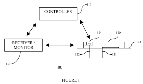
FIG. 1 is a block diagram illustrating an overall therapy management system
for practicing one embodiment of the present invention;
FIGS 2A and 2B illustrate multiple cannulas integrated with an extended use
analyte sensor in a patch pump configuration in accordance with one embodiment
of
the present invention;
FIG. 3 illustrates a combined patch pump system integrated with the second
cannula during the second part of the sensor life in accordance with one
embodiment
of the present invention;
CA 02656581 2008-12-30
WO 2008/005780 PCT/US2007/072287
-3-
FIGS. 4A and 4B illustrate multiple cannulas integrated with an extended use
analyte sensor in a patch pump configuration in accordance with another
embodiment
of the present invention; and
FIGS. 5A and 5B illustrate alternate embodiments showing infusion fluid
provision in accordance with one embodiment of the present invention.
DETAILED DESCRIPTION
As described below, within the scope of the present invention, there are
provided methods and systems for integrating therapeutic fluid infusion
cannula for
use with an on-body patch pump and an analyte sensor configured for continuous
monitoring of a patient's analyte. In particular, within the scope of the
present
invention, there is provided an integrated multiple infusion cannulas with
analyte
sensors for continuous monitoring and infusion for approximately seven days of
continuous use.
FIG. 1 is a block diagram illustrating an overall therapy management system
for practicing one embodiment of the present invention. Referring to FIG. 1,
the
therapy management system 100 includes a controller 110 configured for bi-
directional wireless communication with an on-body patch pump 120. In one
embodiment, the controller 110 is configured to control the operation of the
patch
pump 120 based on, for example, preprogrammed delivery profiles for infusion
of
therapeutic agent, such as, including but not limited to insulin. In one
aspect, the
controller 110 includes one or more user input unit, and one or more user
output unit
for user directed programming of the patch pump 120 using the controller 110,
and
further, to provide visual, auditory, and/or vibratory output signals for
communicating
with the user.
Referring back to FIG. 1, the patch pump 120 in one embodiment is provided
with an adhesive layer 123 which is configured to adhere on the skin of a
patient
during use. The patch pump 120 includes a cannula 121 for establishing a fluid
path
between a reservoir (not shown) containing the therapeutic fluid for delivery
and the
infusion site of the patient. Also shown in the Figure is a sensor 122. As
shown in
CA 02656581 2008-12-30
WO 2008/005780 PCT/US2007/072287
-4-
FIG. 1, a portion of the cannula 121 and the sensor 122 are positioned under
the skin
of the patient, and thus, at least a portion of each are configured to extend
from the
lower surface of the patch pump 120 through the skin layer of the patient.
In one embodiment, the sensor 122 includes an analyte sensor which is
configured to establish fluid contact with the interstitial fluid of the
patient so as to
detect the analyte level, such as glucose level, of the patient. That is, the
transmitter
unit 124 may be configured to receive one or more signals from the analyte
sensor
122 corresponding to the detected analyte levels of the patient, and to
transmit the
information corresponding to the detected analyte levels to the
receiver/monitor 130
and/or the controller 120. In particular, over a communication link such as an
RF
wireless communication link, the transmitter unit 124 may be configured to
transmit
data associated with the detected analyte levels periodically, and/or
intermittently and
repeatedly to one or more other devices such as controller 110 and/or the
receiver/monitor 130 for further data processing and analysis.
Referring back to FIG. 1, in one embodiment, the one or more of the
controller 110 and the receiver/monitor 130 may include a strip port
configured to
receive a test strip for capillary blood glucose testing. In one aspect, the
glucose level
measured using the test strip may in addition, be configured to provide
periodic
calibration of the sensor 122 to assure and improve the accuracy of the
analyte levels
detected by the analyte sensor 122.
Referring again to FIG. 1, the analyte sensor 122 may include, but not limited
to short term subcutaneous analyte sensors or transdermal analyte sensors, for
example, which are configured to detect analyte levels of a patient over a
predetermined time period, and after which, a replacement of the sensors is
necessary.
Additional analytes that may be monitored, determined or detected the analyte
monitoring system 110 include, for example, acetyl choline, amylase, amyln,
bilirubin, cholesterol, chorionic gonadotropin, creatine kinase (e.g., CK-MB),
creatine, DNA, fructosamine, glucose, glutamine, growth hormones, hormones,
ketones, lactate, measures for oxidative stress (such as 8-iso PGF2gamma),
peroxide,
prostate-specific antigen, prothrombin, RNA, thyroid stimulating hormone, and
CA 02656581 2008-12-30
WO 2008/005780 PCT/US2007/072287
-5-
troponin. The concentration of drugs, such as, for example, antibiotics (e.g.,
gentamicin, vancomycin, and the like), biguanides, digitoxin, digoxin, drugs
of abuse,
GLP- 1, insulin, PPAR agonists, sulfonylureas, theophylline,
thiazolidinediones, and
warfarin, may also be determined.
Referring yet again to FIG. 1, both the cannula 121 and the sensor 122 may be
transcutaneously positioned under the skin layer of the patient using an
insertion
device (not shown) that includes a sharp penetrating member such as an
insertion
needle. Alternatively, the sensor 122 and the cannula 121 may be configured
with
sufficient rigidity to pierce through the skin of the patient without
additional piercing
guides such as the sharp penetrating member of the insertion device.
Further, the transmitter unit 124 in one embodiment is configured to maintain
electrical communication with the sensor 122 such that the detected analyte
levels
from the sensor 122 may be transmitted by the transmitter unit 124 to the
controller
110. In this manner, the controller 110 may be configured to communicate with
the
transmitter unit 124 so as to provide analyte monitoring functions.
Alternatively or in addition to the controller 110, there may be provided a
receiver/monitor unit 130 which is configured to communicate with the
transmitter
unit 124 to receive the detected analyte levels for further processing. In one
aspect,
the patch pump 120 control functions and the analyte monitoring functions may
be
incorporated in the controller 110 such that the patient need only carry one
device.
In addition, the receiver/monitor unit 130 in one embodiment may include for
example, a desktop computer terminal, a data communication enabled kiosk, a
laptop
computer, a handheld computing device such as a personal digital assistant
(PDAs),
or a data communication enabled mobile telephone.
Similar to the controller 110 discussed above, the receiver/monitor unit 130
may include a user interface unit which may include a display unit and/or an
audio
output unit such as, for example, a speaker, and/or any other suitable user
interface
mechanism for displaying or informing the user of such devices.
In one embodiment, both the controller 110 and the receive/monitor 130 are
configured with a substantially compact housing and sized such that the
devices may
CA 02656581 2008-12-30
WO 2008/005780 PCT/US2007/072287
-6-
be easily and comfortably be held in the patient's hand, worn on the patient's
clothing, or placed inside a pocket of the patient's clothing without much
discomfort.
In addition, the patch pump 120 may be configured with a substantially compact
housing and sized such that the patient experiences minimal discomfort during
the
seven or more days of continuous on-body use.
FIGS 2A and 2B illustrate multiple cannulas integrated with an extended use
analyte sensor in a patch pump configuration in accordance with one embodiment
of
the present invention. Referring to FIG. 2A, patch pump 210 in one embodiment
includes a controller 230 (e.g., a microprocessor) operatively coupled to an
infusion
management unit (IMU) 220 which includes, among others, a reservoir (not
shown)
for retaining therapeutic agent such as insulin for delivery to the patient.
Within the
scope of the present invention, the infusion management unit (IMU) 220 may
include
other components such as power supply (e.g., battery), and/or fluid path
management
section which, in one embodiment, may be configured to connect the a cannula
240 to
the reservoir for therapeutic agent delivery to the patient, and further, to
control the
placement or positioning of the first cannula 240, and subsequent retraction
of the
first cannula 240 upon reaching the end of its useful life cycle.
Moreover, in one embodiment, the infusion management unit (IMU) 220 may
include a transceiver (not shown) for bi-directional communication with one or
more
of the controller 110 and the receiver/monitor 130. In one embodiment, the
transceiver may be configured to receive infusion related commands or
instruction
from the one or more of the controller 110 and the receiver/monitor 130, and
further,
to transmit one or more information associated with the fluid flow information
or the
operating condition of the patch pump 120.
Referring back to FIG. 2A, the infusion management unit (IMU) 220 in one
embodiment is connected to a port 270 provided substantially at the housing of
the
patch pump 210. In one aspect, the infusion management unit (IMU) 220 is
configured to maintain a fluid path to the port 270. In one embodiment, the
port 270
may include a self-sealing septum which is substantially configured to be
water
proof. In accordance with an alternate embodiment, the port 270 may include a
uni-
CA 02656581 2008-12-30
WO 2008/005780 PCT/US2007/072287
-7-
directional connector for mating with an infusion tubing 280 to establish
fluid path
between the infusion management unit 220 and a second cannula 290 as shown in
FIG. 2B. That is, in one embodiment, the infusion management unit (IMU) 270
may
be configured to manage the infusion of the therapeutic agent such that the
first
cannula 240 transcutaneously positioned at the first infusion site is used for
a
predetermined time period (for example, approximately three to four days), and
thereafter, retract the first cannula 240 from the first infusion site (and
retained within
the housing of the patch pump 210), while connecting the infusion tubing 280
to the
port 270 establishes a fluid path to the second cannula 290 to infuse the
therapeutic
agent to the patient in a continuous manner.
Referring yet again to FIG. 2A, also provided in the patch pump 210 is a
sensor 250 such as, for example, an analyte sensor, at least a portion of
which is
transcutaneously positioned under the skin layer of the patient. As shown, the
sensor
250 is operatively coupled to a transmitter unit 260 which is configured to
communicate with, for example, the controller 110 (FIG. 1) and/or the
receiver/monitor 130 (FIG. 1). In one aspect, the sensor 250 is configured for
approximately seven or more days of use. As such, it is desirable to change
the
infusion site of the therapeutic agent delivery at approximately mid point in
the usage
life of the sensor 250 (i.e., after approximately three or four days of use).
Accordingly, in accordance with one embodiment of the present invention, the
first cannula 240 is configured for transcutaneous delivery of the therapeutic
agent at
the first infusion site for the initial time period of approximately three or
four days.
Thereafter, the first cannula 240 is retracted from the infusion site under
the control
and operation of one or more of the controller 230 and the infusion management
unit
220, and in one embodiment, wholly retained within the housing of the patch
pump
210. Prior to the retraction of the first cannula 240, the infusion tubing 280
connected
to the second cannula 290 is coupled to the port 270 to establish fluid
contact with the
infusion management unit (IMU) 220. This is shown in FIG. 3.
The tubing 280 may be either pre-primed or is primed by the controller 230
and/or the infusion management unit (IMU) 220. In addition, the tip of the
tubing
CA 02656581 2008-12-30
WO 2008/005780 PCT/US2007/072287
-8-
280 for mating or connection to the port 270 may be configured to engage with
the
port 270 so as to establish a water tight seal. Further, the second cannula
290 is
transcutaneously positioned at the second infusion site (which is different
from the
first infusion site on the patient) for delivery of the therapeutic agent.
In one embodiment, the insertion process of the second cannula 290 may be
automated using an insertion device such as an insertion gun that is
configured to
couple to the second cannula 290 (for example, the insertion needle coupled to
the
second cannula 290) and which includes a spring bias driven insertion
mechanism.
Alternatively, the insertion process may be primarily manual whereby the
patient
manually inserts the second cannula at the desired second infusion site.
In this manner, in one embodiment, the patch pump 210 may be configured
for operation for approximately seven or more days for therapeutic agent
delivery,
and further, integrated with a continuous monitoring system wherein the sensor
250 is
configured to continuously monitor the analyte level of the patient during the
seven or
more days of use without interruption. The monitored analyte levels as well as
the
therapeutic agent delivery associated information are communicated to the
controller
110 (FIG. 1) and/or the receiver/monitor 130 by, for example, the transmitter
unit
260. Furthermore, my changing the infusion site for the therapeutic agent
delivery to
the patient, potential for skin irritation and/or damage to patient's tissue
at the
infusion site by the cannula and/or the therapeutic agent may be minimized.
FIGS. 4A and 4B illustrate multiple cannulas integrated with an extended use
analyte sensor in a patch pump configuration in accordance with another
embodiment
of the present invention. Referring to FIG. 4A, patch pump 410 in one
embodiment
includes a first cannula 440 and a second cannula 470 disposed therein. Also
shown
in the Figure is the infusion management unit (IMU) 420 which is operatively
coupled to the first cannula 440 and the second cannula 470.
Further, a controller 430 is operatively coupled to the infusion management
unit (IMU) 420 and to a transmitter unit 460. Similar to the controller 230
discussed
above in conjunction with FIGS. 2A-2B and 3, the controller 430 in one
embodiment
is configured to control the operating functions of the infusion management
unit
CA 02656581 2008-12-30
WO 2008/005780 PCT/US2007/072287
-9-
(IMU) 420 and the transmitter unit 450, for managing therapeutic agent
delivery via
the respective first and second cannulas 440, 470, and for managing the data
transmission of the transmitter unit 460 that is configured to receive one or
more
analyte associated signals from a sensor 450.
Referring back to FIG. 4A, in one embodiment, the initial transcutaneous
placement of the sensor 450 and the first cannula 440 is performed
substantially
simultaneously (or near simultaneously). Thereafter, when a predetermined time
period has lapsed, the first cannula 450 is configured to be withdrawn from
the
infusion site, while the second cannula (pre-deployed) is transcutaneously
inserted
into the patient. An adhesive patch 411 is configured to substantially fixedly
retain
the patch pump 410 on the adhered portion of the patient's skin during the
entire
duration of the patch pump 410 usage (for example, seven or more days).
Referring now to FIG. 4B, it can be seen that the first cannula 440 in one
embodiment is withdrawn from the first infusion site, and substantially and
entirely
retained within the housing of the patch pump 410, while the second cannula
470 is
transcutaneously positioned at the second infusion site. As discussed above,
the
infusion management unit (IMU) 420 in one embodiment includes a reservoir
containing the therapeutic agent, and to establish the appropriate fluid
communication
with the first and second cannulas 440, 470. Optionally, the controller 430
may be
configured to control the operation of the infusion management unit (IMU) 420
so as
to provide continuous and uninterrupted delivery of the therapeutic agent to
the
patient during the duration in which the sensor 450 is detecting the analyte
levels of
the patient.
In one embodiment, the controller 110 (FIG. 1) and/or the receiver/monitor
130 may be configured to substantially control the programming of the patch
pump
410 such that the operation of the infusion management unit (IMU) 420 and the
controller 430 of the patch pump 410 are configured to receive the commands or
instructions from the controller 110 and/or the receiver/monitor 130 to
execute the
appropriate functions. Examples of such functions include, but are not limited
to the
delivery of programmed basal profiles, delivery of carbohydrate bolus dosage,
CA 02656581 2008-12-30
WO 2008/005780 PCT/US2007/072287
-10-
implementing a temporary basal modification, insertion and/or retraction of
the first
cannula 440, and the insertion and/or retraction of the second cannula 470.
In a further embodiment, a mounting base (not shown) may be provided
which includes the adhesive layer 411 there under, and which may be configured
to
guide the insertion of the first cannula 440 and the sensor 450. Further, the
first
cannula 440 and the sensor 450 may be transcutaneously positioned prior to the
placement or positioning of the patch pump 410 on the patient's skin. In this
configuration, the first cannula 440 and the sensor 450 may not be initially
retained
within the housing of the patch pump 410. Rather, an insertion device may be
used to
separately insert the first cannula 440 and the sensor 450. Thereafter, the
patch pump
410 may be configured to couple to the transcutaneously positioned first
cannula 440
and the sensor 450 such that the first cannula establishes fluid contact with
the
infusion management unit (IMU) 420, and the sensor 450 is in electrical
contact with
the transmitter unit 460.
FIGS. 5A and 5B illustrate alternate embodiments showing infusion fluid
provision in accordance with one embodiment of the present invention.
Referring to
FIG. 5A, it can be seen that a first cannula 530 and a second cannula 540 are
coupled
to the reservoir 510, while the reservoir 510 is further coupled to a pre-
filled pouch
520. In one embodiment, the infusion management unit (IMU) 210 or 420 may be
configured to include the first and second cannulas 530, 540, the reservoir
510 and
the pre-filled pouch 520. The pre-filled pouch is configured to hold
therapeutic agent
such as insulin to replenish the reservoir during the usage life of the patch
pump 210,
410.
Referring now to FIG. 513, it can be seen that the first cannula 430 is
coupled
to a first reservoir 510A, while the second cannula 540 is coupled to a second
reservoir 5l OB. Again, the infusion management unit (IMU) 210 or 420 may be
configured to include the first and second cannulas 530, 540, each
respectively
coupled to the first and second reservoirs 510A, 5 1 OB.
Referring back to the Figures, while not shown, the patch pump 210, 410
within the scope of the present invention may include additional components
that are
CA 02656581 2008-12-30
WO 2008/005780 PCT/US2007/072287
-11-
configured to assist and/or improve the therapeutic agent delivery and analyte
monitoring. Such additional components may include, but are not limited to,
one or
more power supplies such as batteries, one or more user input units (e.g.,
mechanical
and/or electromechanical, button, switch, and the like), one or more user
output units
(e.g., a visual indicator, an audible alert, a vibratory alert, or a
combination thereof),
one or more additional redundant microprocessors to protect from failure modes
of
the patch pump 210, 410, or a leakage sensor for detecting any leakage of the
therapeutic agent or any other fluid within the housing of the patch pump 210,
410
that may damage the internal components.
Accordingly, an integrated therapy management system in one embodiment
includes a first cannula for transcutaneous placement under a skin layer of a
patient at
a first infusion site for a first time period, a second cannula for
transcutaneous
placement under the skin layer of the patient at a second infusion site for a
second
time period, and an analyte sensor configured for fluid contact with an
analyte of the
patient for a predetermined time period, where the first cannula and the
second
cannula are configured to deliver a therapeutic agent to the patient during
the
predetermined time period.
There may be also provided a housing, where the first cannula, the second
cannula and the sensor are coupled to the housing.
Further, there may be provided a housing, where the first cannula and the
sensor are coupled to the housing, and further, where second cannula may be
connected to the housing by an infusion tubing.
In one aspect, the first infusion site and the second infusion site may be
separated by a predetermined distance.
Also, the predetermined time period may include approximately seven days.
The system may also include a reservoir coupled to the first cannula and the
second cannula.
In a further aspect, there may be provided a first reservoir coupled to the
first
cannula, and a second reservoir coupled to the second cannula.
CA 02656581 2008-12-30
WO 2008/005780 PCT/US2007/072287
-12-
Moreover, when the second cannula is transcutaneously positioned, the first
cannula may be withdrawn from the first infusion site.
The sensor may include an analyte sensor, and the therapeutic agent may
include insulin.
A method in accordance with another embodiment includes positioning a
portion of a first cannula under the skin of a patient, positioning a portion
of a sensor
under the skin of the patient, positioning a portion of a second cannula under
the skin
of a patient, and withdrawing the first cannula from the patient while
retaining the
sensor position under the skin of the patient.
The positioning the portion of the first cannula and the positioning the
portion
of the sensor may be substantially simultaneously performed.
In yet a further aspect, the sensor may be positioned under the skin of the
patient for approximately seven days.
An integrated therapy management system in accordance with still another
embodiment includes an on-body micropump including a first cannula for
transcutaneous placement under a skin layer of a patient at a first infusion
site for a
first time period, a second cannula for transcutaneous placement under the
skin layer
of the patient at a second infusion site for a second time period, an analyte
sensor
configured for fluid contact with an analyte of the patient for a
predetermined time
period, and a controller in signal communication with the on-body micropump,
the
controller configured to transmit one or more signals to the micropump to
control the
delivery of a therapeutic agent to the patient using one or more of the first
cannula
and the second cannula.
The micropump may further include a transmitter unit operatively coupled to
the analyte sensor.
The controller may be configured to receive one or more signals associated
with one or more analyte levels of the patient from the transmitter unit.
In addition, the controller may be further configured to receive one or more
signals associated with the therapeutic agent delivery.
CA 02656581 2008-12-30
WO 2008/005780 PCT/US2007/072287
-13-
Moreover, in yet a further aspect, the controller may be in signal
communication with the on-body micropump over a wireless communication link.
A kit in yet a further embodiment includes a first cannula for transcutaneous
placement under a skin layer of a patient at a first infusion site for a first
time period,
a second cannula for transcutaneous placement under the skin layer of the
patient at a
second infusion site for a second time period, and an analyte sensor
configured for
fluid contact with an analyte of the patient for a predetermined time period,
where the
first cannula and the second cannula are configured to deliver a therapeutic
agent to
the patient during the predetermined time period.
The kit may also include a housing, where the first cannula, the second
cannula and the sensor are coupled to the housing.
Moreover, the kit may include a housing, where the first cannula and the
sensor are coupled to the housing, and further, where second cannula may be
connected to the housing by an infusion tubing.
In a further aspect, the kit may include a reservoir coupled to the first
cannula
and the second cannula, or alternatively, the kit may include a first
reservoir coupled
to the first cannula, and a second reservoir coupled to the second cannula.
Various other modifications and alterations in the structure and method of
operation of this invention will be apparent to those skilled in the art
without
departing from the scope and spirit of the invention. Although the invention
has been
described in connection with specific preferred embodiments, it should be
understood
that the invention as claimed should not be unduly limited to such specific
embodiments. It is intended that the following claims define the scope of the
present
invention and that structures and methods within the scope of these claims and
their
equivalents be covered thereby.