Note: Descriptions are shown in the official language in which they were submitted.
- - - ,
CA 02657054 2009-03-04
1
PITOT TUBE PRESSURE SENSOR FOR RADIANT TUBE HEATER
This invention relates to burner assemblies for radiant tube heaters
and, in particular, pressure sensors for use with such burner assemblies.
A known type of radiant heater for heating the interior of buildings
and other areas is a so-called radiant tube heater which has a relatively
long, radiant tube made of a suitable metal and adapted to enclose an
elongate flame projected from a burner head. This heater includes a
combustion air blower, a burner nozzle connected to a combustible gas
supply through a gas valve unit, and a burner head connected to the
nozzle. The nozzle and head are positioned in a combustion air duct
section forming a passage for combustion air and the outlet of the blower
is attached to an inlet end of this duct section so that the blower is able to
direct combustion air through the duct section. The burner head which in
an exemplary embodiment is arranged centrally in the air duct section,
creates an annular passageway between itself and the air duct section.
Combustible gas, such as natural gas, is delivered to the radiant heater
through a gas valve governor which is connected by a line to the burner
nozzle. Combustion air enters the burner head through vents or ports in
the side wall of an inlet portion of the head and then mixes with the fuel,
thereby producing a gas/air mixture which can exit through a perforated
ceramic tile mounted in a downstream end of the head. The mixture is
ignited by a suitable electrode resulting in a long laminer flame extending
down the radiant tube.
One exemplary form of radiant tube heater is described and
illustrated in co-pending Canadian Patent Application No. 2,595,752 filed
July 30, 2007 and laid open July 26, 2008. This radiant tube heater in
addition to including the aforementioned features, employs a tubular
arrangement that includes an air duct portion forming a combustion air
passage and a radiant tube portion which is heated. An airflow restricting
plate is mounted in the air duct portion and extends circumferentially
around the burner head. This plate increases the flow of pressurized
CA 02657054 2009-03-04
2
combustion air through the openings formed in the inlet portion of the
burner head but also allows a substantial portion of the combustion air to
flow downstream between the wider outlet portion of the head and the air
duct portion.
The blower for the aforementioned radiant tube heater has a
blower housing with a relatively straight, outlet section. Mounted on an
outer wall of this outlet section are two pressure switches in the form of
pitot tubes of standard construction. These switches are provided to
ensure that the blower is in operation and is providing sufficient
combustion air to the burner head when the mixture of combustion air
and gas is ignited. The heater is constructed so as not to operate unless
sufficient combustion air is being provided to the heater.
There is disclosed herein a pitot tube assembly for a radiant tube
heater having a blower for providing combustion air to a burner assembly,
this pitot tube assembly being constructed to provide a more accurate
reading of static pressure when the tube heater is in use.
According to one embodiment of the invention, a pitot tube
assembly for a radiant tube heater having a blower for providing
combustion air to a burner assembly includes a mounting plate for
attaching the pitot tube assembly to a wall of a housing of the blower.
The assembly further includes first and second, substantially L-shaped
pitot tubes that extend through the mounting plate and are connected
thereto. These tubes have respective inner leg sections which are
arranged within an outlet section of the blower during use of the radiant
tube heater and which extend in opposite directions to their respective
pressure sensing ends. The first pitot tube is adapted to measure impact
pressure created by the blower and the second pitot tube is adapted to
measure static pressure during use of the blower. These pitot tubes are
adapted for connection to a differential pressure switch arrangement for
controlling operation of the burner assembly.
In an exemplary version of this pitot tube assembly, the mounting
plate is flat and is sized to close both a relatively small hole and a
CA 02657054 2009-03-04
3
separate, larger elongate slot in the wall of the housing during use of the
assembly. During such use, the first pitot tube extends through the slot
and the second pitot tube extends through the small hole.
According to another embodiment of the invention, a heating
assembly for a radiant tube heater having a radiant heating burner tube
with an upstream end includes a mixing cup assembly adapted for
mounting within the burner tube and adapted for mixing primary air and
combustible gas and for delivering the resulting mixture into an upstream
end section of the burner tube. A gas line for introducing the combustible
gas into the mixing cup assembly has an upstream first end and a
downstream second end terminating in the mixing cup assembly. A gas
valve unit is provided for a connection to the first end of the gas line and
for regulating flow of the combustible gas to the mixing cup assembly. A
blower is able to provide the primary air for combustion to the mixing cup
assembly and includes a blower housing with a blower outlet section
adapted for connection to the upstream end of the burner tube. The
heating assembly also includes a pressure sensor system for controlling
the gas valve unit, this system including a differential pressure switch
arrangement and a pitot tube assembly mounted on the blower outlet
section so as to extend through a wall of this outlet section. The pitot
tube assembly is operatively connected to the pressure switch
arrangement and includes first and second substantially L-shaped pitot
tubes having respective inner leg sections located within the blower outlet
section and extending in opposite directions to their respective pressure-
sensing ends. The first pitot tube is adapted to and mounted to measure
impact pressure created by the blower during use of the heating assembly
and the second pitot tube is adapted to and mounted to measure static
pressure during use of the heating assembly. The pitot tube assembly is
adapted to sense pressure changes and to provide details of these
changes to the differential pressure switch arrangement for controlling
operation of the gas valve unit.
CA 02657054 2009-03-04
"
4
In an exemplary version of this heating assembly, the blower outlet
section has a mounting flange plate on a downstream end thereof for
connecting the blower housing to the upstream end of the burner tube.
The inner leg section of the second pitot tube extends through a blower
outlet opening formed in the flange plate.
Further features and advantages will become apparent from the
following detailed description of an exemplary embodiment of the
invention taken in conjunction with the accompanying drawings.
In the drawings,
Figure 1 is a schematic, cross-sectional view of a radiant tube
heater in use, this view showing an elongate laminar flame extending
from a burner head, a major portion of the radiant tube being omitted
along with its reflector/shield for illustration purposes;
Figure 2 is another schematic cross-sectional view similar to Figure
1 showing another embodiment of a radiant tube heater;
Figure 3a is a perspective view of the burner head taken from one
side and from the upstream end;
Figure 3b is a perspective view similar to Figure 3a but showing a
restricting plate mounted on the burner head;
Figure 4 is an axial cross-section of the burner head of Figure 3a;
Figure 5 is a downstream end view of the burner head;
Figure 6 is an end view of the blower of the radiant tube heater,
together with its mounting flange or mounting plate;
Figure 7 is a detail view of one form of mounting flange for the
blower, this view showing the downstream side;
Figure 8 is a perspective view of the blower and its mounting
flange, this view being taken from the motor side of the blower and
showing the upstream side of the flange;
Figure 9 is a side view of the burner head and the blower of Figure
8, together with its mounting flange, this view showing a pitot tube
assembly mounted on an outlet section of the blower housing;
CA 02657054 2009-03-04
= 5
Figure 10 is a cross-sectional view of the blower and its mounting
flange, this view being taken along the line X-X of Figure 9;
Figure 11 is an inner side view of a pitot tube assembly, this view
showing the side of its mounting plate which faces the blower housing
wall;
Figure 12 is a perspective view of the pitot tube assembly, this view
showing the side of the mounting plate which faces away from the blower
housing;
Figure 13 is a perspective view showing a housing for the blower
and its motor and a portion of the radiant tube which extends from one
end of this housing;
Figure 14 is a perspective view of the housing of Figure 13 with the
housing being shown in an open position showing the location of the
blower and other components of the heater unit;
Figure 15 is a perspective view showing the housing of Figure 14 in
the closed position, a reflector/shield extending from the housing and an
elongate radiant tube arranged within the reflector/shield; and
Figure 16 is a perspective view of the burner head fitted with a
diverter ring at its upstream end;
Figure 17 is a graph showing real times in seconds to obtain
pressure readings in ten tests of the burner assembly using a pitot tube
assembly with one bent tube and using an assembly with two bent tubes;
and
Figure 18 is an electrical circuit diagram illustrating the control
circuit for the radiant tube heater.
In the detailed description which follows, exemplary embodiments
are described, particularly with reference to the figures appended thereto.
However, the particularly described embodiments are merely illustrative
of radiant tube heaters and pitot tube assemblies for sensing pressure
constructed according to the present disclosure.
Referring now to the drawings, wherein like reference numerals
identify similar structural elements of the heating units, Figures 1 and 2
_
CA 02657054 2009-03-04
6
illustrated schematically embodiments of radiant tube heaters constructed
in accordance with co-pending Canadian Patent Application No. 2,595,752
filed July 30, 2007. The radiant tube heater includes an elongate heating
tube 66, only an upstream portion of which is shown for ease of
illustration. This cylindrical tube can comprise several sections arranged
end to end. The length of a heating tube can extend ten feet or more and
the tube encloses an elongate flame 14 during use. The tube is heated by
the flame and combustion gases to emit infrared radiant heat. Preferably
the tube is located within or under a downwardly opening, trough-shaped
reflector/shield such as that shown in Figure 15. This reflector/shield of
the heater receives upwardly-directed radiant energy from the tube and
reflects or radiates this energy downwardly to an area or region requiring
heating. Also shown is a gas valve governor, also referred to herein as a
gas valve unit 16 for the heater which is adapted for connection to a first
end 21 of a gas pipe or gas line 20, this line extending to a burner nozzle
at 32 and a burner head 92 mounted on the nozzle. The heating assembly
in each of Figures 1 and 2 includes a blower or blower fan 22 having a
side air inlet 24 into which external air is drawn. The blower has an outlet
section which extends tangentionally relative to the blower fan and which
is connected to the upstream end of the burner tube 66.
The burner head or mixing cup assembly 92 is adapted for
mounting within the burner tube 66 and is adapted for mixing primary air
and combustible gas and for delivering the resulting mixture into an
upstream end section of the burner tube as shown. The burner head is
generally annular and has a cylindrical inlet portion 96 and a wider
cylindrical outlet portion 102 integrally connected to the inlet portion and
located at the downstream end of the inlet portion. The aforementioned
nozzle 32 extends into the inlet portion and can be connected thereto by
a thread connection, including internal threads 108 formed at the
upstream end section of the inlet portion 96 (see Figures 3a and 3b).
It will be understood that the heater is provided with natural gas or
LPG gas indicated by the arrow G taken from a suitable source and
CA 02657054 2009-03-04
=
7
delivered through the gas valve governor 16 and the pipe or line 20 to the
burner nozzle. Combustion air enters through vents or ports distributed
about the periphery of the inlet portion 96. In the burner head, the gas
intermingles with the combustion air to produce a gas/air mixture that
exits the burner head through a perforated ceramic tile 46 located at the
downstream end of the outlet portion 102. The exiting mixture is ignited
by an ionization electrode 48 of an igniter 50 so as to produce a long
laminar flame that extends substantially the length of the tube 66. The
preferred material for the radiant tube is stainless steel or aluminized
steel, at least for an upstream section thereof that surrounds the flame
and the burner head. The remaining downstream section can be cold
rolled steel. A typical dimension for such a heating tube is four inches in
diameter and the tube sections can be provided in standard lengths of ten
feet each which are connected together end-to-end. Typically two to five
such radiant tube sections are connected together to form a complete
heating tube which can be connected at the downstream end to a suitable
exhaust pipe or passage.
The illustrated heating tube is an elongate tubular arrangement
that includes an air duct portion 62 forming a combustion air passage and
a radiant tube portion which is the portion actually heated by and
surrounding the laminar flame during use of the heater and which extends
downstream of the air duct portion in relation to the flow of combustion
air in the air passage 64. The air duct section has a central longitudinal
axis indicated at 68 in Figure 1, an inlet end 70 forming an air inlet for
receiving combustion air and an opposite end located approximately at
the dash line 72 where the air duct portion integrally connects to the
radiant tube portion.
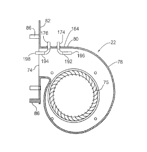
The blower 22 has an air outlet 74 which can be rectangular as
shown in Figures 6 and 7. The blower is able to provide pressurized
combustion air to the inlet end of the air duct section and its housing is
sealingly connected to this air duct section at the inlet end 70 thereof.
The blower can include a blower fan 75 of the squirrel cage type, a radial
CA 02657054 2009-03-04
= 8
cross-section of which can be seen in Figure 10. The direction of rotation
of the fan is indicated by the arrows B in Figure 1. The blower includes a
blower casing or housing 78 having an outlet section 80 forming the
blower outlet. The blower can include an attachment arrangement for
connecting the outlet section 80 to the inlet end of the air duct portion 62.
This attachment arrangement can include a rectangular mounting flange
82 that extends around the outlet formed by outlet section 80. The
mounting flange 82 is connected by means of bolts 86 to a mounting
flange 84 provided at the inlet end of the burner tube. The flange plate 82
shown in Figures 6 and 7 has six bolt holes 83 to accommodate six of the
connecting bolts 86 but the number of holes can be fewer or more. Nuts
(not shown) are threaded onto these bolts in order to connect the two
mounting flanges together. An equalizer plate 88 shown in Figure 6 has
an array of air holes 89 formed therein for the passage of combustion air.
This plate can be mounted between the two mounting flanges 82, 84 and
held in place by at least some of the bolts 86. The function of this
equalizer plate is to help distribute the combustion air evenly across the
height and width of the air duct section 62. The blower can be powered by
an electric motor 90 which in one embodiment is a 1/35 hp, 120 V 60Hz
motor.
Figures 3a to 5 illustrate one embodiment of the burner head 92 for
the tube heater while a variant of this burner head is shown in Figures 9
and 16. As seen in Figure 3a, the inlet portion 96 of the burner head has
an upstream end 98 and a downstream end 100. The substantially
cylindrical outlet portion 102 is located at the downstream end of the inlet
portion. The diameter of the outlet portion is substantially greater than
the transverse dimensions of the inlet portion which also has a cylindrical
exterior. In the illustrated embodiment there are four openings or ports
104 distributed about the periphery of the inlet portion for passage of
combustion air into the burner head but there could be fewer or more of
these ports. Extending along the longitudinal center line of the inlet
portion is an axial passage 106 which is open ended. At the upstream
=
CA 02657054 2009-03-04
9
end, this passage is threaded at 108, these threads being used to attach
the nozzle 32 which has exterior threads.
The outlet portion 102 is substantially hollow, except for the
perforated ceramic tile 46. This tile has an array of small holes distributed
in a radial and circumferential pattern over its surface as shown in Figure
5. These holes allow a mixture of combustion air and gas to flow smoothly
and evenly out of the burner head. If desired, the tile can be formed with
a cylindrical center hole which in one embodiment has a diameter of
3/8ths inch. This center hole can be desirable for burners with a low firing
input rate and can be omitted in burners with a high firing rate. The tile
can be held in the end section of the burner head using any one of several
possible attachment techniques. For example, the internal wall of the
burner head can be formed with a downstream facing shoulder at 112 to
engage and locate one side of the tile. Near the downstream end of the
outlet portion there can be formed an internal circumferential groove to
receive a clip such as a flexible metal C-clip which is sized to fit into the
groove and to engage and hold the downstream face of the tile.
Alternatively, the tile could be formed with radially extending holes in its
circumferential edge to accommodate short threaded fasteners that
extends through the wall of the outlet portion into the tile.
The inlet and outlet portions of the burner head are rigidly and
integrally connected to each other by an annular disk or wall 114 having a
plurality of apertures 116 formed therein as shown in Figures 3a and 16.
The arrangement of the wall 114 allows a flat restricting plate 94 to be
mounted immediately against the wall as shown in Figure 3b. The burner
head, as illustrated, can be connected to and supported by the burner
nozzle 32 but it can be supported by other means, for example, by
securing it to the aforementioned restricting plate 94 and then securing
the restricting plate to the air duct section.
The illustrated restricting plate 94 has a circular perimeter and is
an annular plate with a central circular hole at 120 having a diameter
slightly greater than the diameter of the inlet portion 96. The plate 94
CA 02657054 2009-03-04
= 10
substantially spans the combustion air passage 64 between the burner
head and the air duct section. The plate is formed with an array of air
holes 122 distributed over the plate for the passage of combustion air
through the plate. The radial innermost holes 122' can be the same in
number and size as the apertures 116 formed in the radial wall 114 but it
is possible to have fewer holes 122' for some burner applications. By
providing fewer holes 122', the plate can be used to restrict air flow into
the outlet portion. The holes 122' are aligned with some or all of the
apertures 116 so that combustion air can flow through them. Two
outermost rows of air holes 122 are located beyond the circumferential
perimeter of the outlet portion and these holes allow a substantial laminar
air flow downstream of the restricting plate around the circumference of
the outlet portion 102. Depending on the burner performance
requirements, the number of these holes can be increased or decreased
and there may be only one outer row of holes beyond the circumference
of the outlet portion. The presence of the plate 94 increases the flow of
pressurized combustion air through the ports 104 in the inlet portion and
this increases the efficiency of the burner by providing turbulent flow in at
least a central region of the outlet portion which improves mixing.
It is possible and sometimes desirable to mount the restricting
plate 94 downstream from the position shown in Figure 1 and along the
exterior of the outlet portion 102. One such alternative location is
indicated by the dash line 126 in Figure 2. When the restricting plate is in
the position shown in Figures 1 and 3b, it can be secured in this position
by a small screw, not shown, extending through a hole in the plate and
extending into the annular wall 114. There are various possible ways of
securing the restricting plate midway along the outlet portion as shown in
Figure 2, for example, by forming a shoulder on the exterior of the outlet
portion against which the restricting plate can rest. The plate can be held
against this shoulder by means of a C-clip mounted in a groove formed
about the exterior of the outlet portion. The restricting plate can be
located at the juncture between the inlet portion and the outlet portion
_ - -
CA 02657054 2009-03-04
11
when the heater has a burner with high firing input rates, for example, in
the range of 130 and 200 BTU/hour. For lower firing input rates, it can be
desirable to move the restricting plate further downstream.
The radiant tube heater can be provided with an igniter 50 for
mounting adjacent to the burner assembly for igniting the mixture of
combustible gas and air. The igniter has an electrode 48 extending
therefrom and projecting in front of the ceramic tile. In the embodiment
shown in Figure 1, the igniter is secured to the side of the burner head. In
the exemplary embodiment shown in Figure 2, the igniter is secured to
the radiant tube 66 and projects through a hole in the tube. A mounting
plate 130 is used to mount the igniter on the wall of the tube so that the
igniter projects into the radiant tube portion. The mounting plate can be
secured in position by means of screws.
Shown in Figures 13 to 15 is one form of housing 132 in which can
be mounted the blower. This housing is shown in a closed position in
Figures 13 and 15 and in a swung open position in Figure 14. The inlet of
the blower extends to a side opening 134 in the housing so that exterior
air can flow into the blower. The illustrated housing has a rectangular end
wall 136 and two opposite side walls 138, 140 connected to the end wall.
Also extending between the side walls is a rectangular wall or panel 142.
Pivotably attached to the ends of the sidewalls is an end portion 144 and
on this end portion can be mounted the blower. The end portion includes
a plate 145 in which the opening 134 is formed. Since the blower outlet is
normally attached to the burner tube, the end portion 144 is normally
fixed in position while the blower cover formed by the walls 136 to 142 is
pivotal from the closed position of Figures 13 and 15 to an open position.
There can be attached to the fixed end portion 144 a
reflector/shield 150 which in use receives upwardly directed radiant
energy from the radiant heating tube 66. The shield can have side walls
152, 156 and end walls 158 and 160 and these walls can be formed with
polished, reflecting interior surfaces in order to radiate the radiant energy
_
CA 02657054 2009-03-04
12
downwardly or towards any desired location. The reflector/shield can be a
trough-shaped channel which is open on the downward side.
Also shown mounted to the interior of the housing 132 are two
differential pressure switches 170, 172 which can be of standard
construction and which together provide differential pressure switch
means for controlling the gas valve unit. These switches are provided to
ensure the blower is in operation and is providing sufficient combustion
air to the burner head when the mixture of combustion air and gas is
being ignited. The switches are connected by flexible tubes to two pitot
tubes 174, 176 which are part of a pitot tube assembly illustrated
separately in Figures 11 and 12. The pitot tubes provide pressure sensors
which are part of the control system for the heating assembly. The radiant
heater is controlled so that it will not operate unless sufficient combustion
air is being provided to the radiant heater by the blower. Also shown in
Figure 14 is an electrical controller 190 used to electronically control the
operation of the radiant tube heater. This controller is connected to
receive electrical signals from the pressure switches 170, 172.
The aforementioned pitot tubes, which can be referred to as first
pitot tube 174 and second pitot tube 176 are part of a pitot tube assembly
180 for the radiant tube heater. This assembly, in addition to the pitot
tubes, includes a mounting plate 182 for attaching the assembly to a wall
184 of the blower casing. As illustrated, the mounting plate is flat and
rectangular and is sized to close both a relatively small hole 186 and a
separate, larger elongate slot 188 in the wall 184 (see Figure 8) of the
casing during use of the pitot tube assembly. It will be understood that in
order to install the pitot tubes, the second pitot tube 176 is manipulated
through the hole 186 and, once this is done, the first pitot tube 174 can
be inserted through the slot. The mounting plate can then be secured to
the wall by means of fastener means such as a single screw 190. Because
of the extended length of the mounting plate, the slot is entirely closed off
and effectively sealed.
CA 02657054 2009-03-04
13
The pitot tubes are substantially L-shaped as can be seen clearly in
Figures 10 and 12. Each has an inner leg section 192, 194 and a further
leg section which extends through the wall of the casing. The two leg
sections are joined at a rounded corner which bends to an angle of 900
approximately. The inner leg sections are arranged within the outlet
section 80 of the blower during use of the radiant tube heater and they
extend in opposite directions to their respective pressure sensing ends
196, 198. The first pitot tube 174, which is closest to the fan wheel, is
adapted to measure impact pressure by the blower while the second pitot
tube 176 is adapted to measure static pressure. As indicated, the tubes
are operatively connected to the differential pressure switches which act
to control the operation of the burner assembly. It will be understood that
the pivot tube assembly and, in particular the pitot tubes, are adapted to
sense pressure changes and to provide details of these changes to the
differential pressure switches.
As can be seen from Figure 10, the inner leg section 194 of the
second pitot tube extends through the air outlet or blower outlet 74
formed centrally in the mounting flange plate 82. By making the pitot 176
L-shaped and placing its pressure sensing end 198 in the illustrated
position, a more accurate static pressure reading can be obtained by this
pressure sensor. This is believed to be due to the fact that the pressure
sensing end 198 is placed further from the blower fan 75 and thus the air
flow in the vicinity of the end 198 is less turbulent than the air flow closer
to the fan. The result of this pitot tube arrangement is better control of
the gas valve unit by the pressure switches.
Also shown in Figures 11 and 12 is a fastener hole 200 through
which the screw 190 extends to attach the mounting plate. Welding or
brazing at 202 can be used to sealingly connect each pitot tube to the
mounting plate. In one exemplary embodiment of the pitot tube
assembly, the length of the mounting plate was 2.4 inches and the length
L of the inner leg section 194 measured from the axial center line of the
outwardly projecting leg section is about 1.2 inch. The distance D
_
CA 02657054 2009-03-04
14
between the two parallel center lines of the outwardly projecting legs of
the pitot tubes is about 0.9 inch.
Figure 18 illustrates an exemplary form of an electrical circuit for
one embodiment of the radiant tube heater. This embodiment is powered
by a 24 volt AC transformer 240 which is powered by 110 volt line voltage
through a terminal block 242 to which electrical plug 244 is connected.
The burner can be activated when a 24 volt thermostat calls for heat and
this thermostat can be connected at 246, 248. In the alternative, if a line
voltage thermostat is used, a jumper connects the terminals at 246, 248
and the line voltage thermostat is installed in series with the power
supply. On a call for heat, the control system will delay start up to
provide a 30 second system pre-purge. When the burner is activated by
the thermostat or a call for heat, the transformer 240 provides power to
an electronic circuit including a direct spark ignition (DSI) control 190 and
safety lockout timing begins. At the same time the control module for the
burner opens the main gas valve 16 allowing gas to flow to the burner.
The control module for the unit performs several basic functions including
providing the aforementioned 30 second system pre-purge, supplying
power to the electronic pulse-generator control 190 for spark ignition
(30,000 volts open circuit), and allowing 21 seconds for ignition trial
before system safety lockout occurs. The control module is also able to
sense the burner flame for safe lighting and to shut off the spark after the
burner is lit.
The operating sequence then for the exemplary form of burner is
that, upon a call for heat from the online voltage thermostat or an on/off
switch, the blower 22 and the transformer 240 are powered
simultaneously with 115 volts. Alternatively, if a 24 volt thermostat is
used, the line voltage will power the transformer 240 and the 120 volt
side of a blower switching relay 250 simultaneously. The call for heat by
the 24 volt thermostat energizes the 24 volt control circuit and the 24
V/120 volt relay 250 powering the blower. The 24 volt control circuit
powers the DSI control 190 in series through the normally open air
CA 02 657054 2 00 9-03-04
pressure switch (APS) 172 and the normally closed blocked flue switch
170. Proper operation of the blower 22 creates a positive pressure and
closes a normally open contact inside the APS 172. The 24 volt supplied
to the DSI control 190 initiates the aforementioned 30 second pre-purge
5 cycle. After this cycle is completed the DSI control 190 generates high
voltage to the spark igniter and 24 volts to energize the gas valve 16.
The burner will then light and establish a steady flame. Once a flame
sensor determines there is a steady flame established, with a minimum
flame signal of 1.5 uA, the spark igniter 50 is then de-energized. In the
10 event ignition does not occur, a safety circuit will function to
interrupt gas
flow after approximately 21 seconds and lock the system out. No further
gas will flow until the power has been manually interrupted for a period of
30 seconds. This will reset the ignition module and the operating
sequence will restart. If the blower does not run, the APS 172 does not
15 close and power is not supplied to the ignition control.
The clear advantage of using the pitot tube assembly illustrated in
Figures 10 to 12 was established by comparative tests measuring real
time in seconds to obtain a pressure reading of 0.7 inches water column.
The results of these tests are reflected in table 1 set out below:
Table 1
Test Number 1 2 3 4 5 6 7 8 9 10
two-curved 2.60 2.80 2.84 2.80 2.62 2.65 2.72 2.82 2.8 2.75
pitot tube
One-curved 3.1 3.15 3.25 2.98 2.99 3.25 3.20 3.15 3.30 3.29
pitot tube
As indicated in table 1, the real time results of using a pitot tube
assembly with two-curved pitot tubes was compared to the results of a
two pitot tube assembly wherein only the pitot tube 174 is curved, that is
the pitot tube connected to air proving switch 172. It was indicated by
these tests that the average time for the two curved pitot tubes assembly
is 2.74 seconds while the average time for the one curved pitot tube
assembly (with one straight tube) is 3.166 seconds. The difference of
CA 02657054 2009-03-04
16
0.426 seconds or 426 milliseconds is important in controlling combustion
to avoid the affects of backfire in the radiant tube heater. The
aforementioned test results are also reflected in the graph of Figure 17.
Figures 9 and 16 illustrate an exemplary feature of the burner
assembly. In order to improve the distribution of the combustion air
across the height and width of the air duct portion 62, there can be
provided a diverter ring 210 having a number of diverter blades 212
extending about its circumference. This ring can be made from a single
metal plate which is preferably aluminized steel. It has a central circular
hole at 214 through which a reduced cylindrical end section 216 of a
modified burner head extends. Surrounding the central hole in the plate is
an annular connecting section 218 of the plate, the blades extending
outwardly from this connecting section. As shown, each blade has a first
section 220, which extends in the same radial plane as the connecting
section and a second sloping section 222. The blades can be made by a
straightforward metal stamping process. It is also possible to construct
the diverter ring wherein the whole of each blade extends at an angle to
the radial plane. The blades help to circulate and mix the incoming
combustion air and help to prevent backfire because of the improved
circulation. The ring does not rotate and is in fact fixedly held in position
by means of a screw (not shown) that extends through the connecting
section 218 and into the rearwardly facing shoulder formed on the inlet
portion 96'. The slope of the angular portion of each blade can vary and
typically is 30, 45 or 60 degrees relative to the plane of the flat first
section 220 of the blade. The best angle for a particular burner application
can be determined by trial and error. These diverter rings are only for low
firing rate burners, typically in the 60,000 to 90,000 BTU range.
Aluminized steel for the diverter is preferred as it can withstand the
heat given off by the burner and it will not corrode in this environment.
Figure 8 illustrates a rectangular side opening 226 formed in the
outlet section of the blower casing. It will be understood that the gas line
that extends from the gas valve unit to the gas nozzle extends through
CA 02657054 2015-06-15
17
this opening which is sealed off around the gas line. The blower has two
opposing side walls 230, 232 extending perpendicular to the axis of
rotation of the fan 75 of the blower. The opening 226 is formed in the side
wall 230 adjacent the downstream end of the blower outlet section 80.
While the present invention has been illustrated and described as
embodied in certain exemplary embodiments, it is to be understood that
the present invention is not limited to the details shown herein, since it
will be understood that various omissions, modifications, substitutions and
changes in the form and details of the disclosed heating assembly and
pitot tube assembly can be made by those skilled in the art. For example,
those with ordinary skill in the art will readily adapt the present disclosure
for various other applications.