Note: Descriptions are shown in the official language in which they were submitted.
CA 02657613 2009-01-12
WO 2008/011062 PCT/US2007/016277
SYSTEMS AND METHODS FOR PROVIDING MILLIIVIETER WAVE
SIGNAL IMPROVEMENTS
1. Field of the Invention
[0001] The invention relates in general to systems and methods for wireless
transmissions, and in particular to improving millimeter wave signals.
2. Background
[0002] There has recently been a pronounced increase in the types of
communication applications that require the use of wireless data transfer.
Such applications include, for example, video conferencing, video-on-
demand, high speed Internet access, high speed local area networks,
online gaming, and high definition television. In the home or office, for
example, computing devices continue to be connected using wireless
networking systems. Many additional types of devices are also being
designed with wireless communication in mind.
[0003] At frequencies below about below 3 GHz, antennas are generally
omnidirectional, which cause antennas in proximity to interfere with each
other, or experience what is known as "multipath." At higher frequencies
(e.g. from about 3 to about 60 GHz), signals become somewhat directional,
which reduces the multipath issue mentioned above. However, at very
close distances signal reflections off of the receiver and transmitter
reintroduce the multipath issue. These reflections cause signal
interference and degrade the overall quality of the communication.
[0004] The 57 - 64 GHz ("60 GHz band") band is located in the millimeter-
wave portion of the electromagnetic spectrum and has been largely
unexploited for commercial wireless applications. In addition to the
higher-data rates that can be accomplished in this spectrum, energy
propagation in the 60 GHz band has unique characteristics that make
possible many other benefits such as excellent immunity to interference,
high security, and frequency re-use.
[0005] While wireless transmissions in the 60 GHz range exhibit the
aforementioned beneficial characteristics, they still suffer from certain
CA 02657613 2009-01-12
WO 2008/011062 PCT/US2007/016277
drawbacks, including the fact that such transmission typically only span a
maximum distance measured in tens of meters. As mentioned above, very
short distances between the receiver-side and transmitter-side of a high
frequency system will reintroduce the multipath issue and cause signal
reception interference. As such, there is a need in the art for a system and
method which improves signal quality at millimeter wave frequencies by
reducing multipath effects.
AttyDocketNo.: 101162.56141 WO -2- Initial July 17, 20(
CA 02657613 2009-01-12
WO 2008/011062 PCT/US2007/016277
BRIEF SUMMARY OF THE INVENTION
[0006] Disclosed and claimed herein are systems and methods for providing
millimeter wave signal improvements. In one embodiment, a radio
frequency receiver includes a receiver circuit for processing radio
frequency (RF) signals, an antenna to receive millimeter wave RF signals,
and an attenuator circuit, coupled between the receiver circuit and
antenna. In one embodiment, the attenuator circuit may be used to
determine a signal strength of the millimeter wave RF signals, compare
this signal strength to a first threshold value. If the signal strength is
above the first threshold value, a level of attenuation applied to the
millimeter wave RF signals may then be increased.
[0007] Other aspects, features, and techniques of the invention will be
apparent to one skilled in the relevant art in view of the following
description of the exemplary embodiments of the invention.
Atty Docket No,: 101162.56141 WO -3- Initial July 17,20
CA 02657613 2009-01-12
WO 2008/011062 PCT/US2007/016277
BRIEF DESCRIPTION OF DRAWINGS
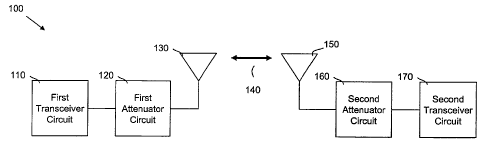
[0008] FIG. 1A is one embodiment of a transmission system for carrying out
one or more aspects of the invention;
[0009] FIG. 1B is a diagram showing how an attenuator of FIG. 1A may
attenuate an RF signal;
[0010] FIG. 1C depicts wireless signal reflection without attenuation;
[0011] FIG. YD depicts one embodiment of wireless signal reflection with
attenuation;
[0012] FIGs. 2A - 2B are process diagrams of how a receiver may be used to
carry out one or more embodiments of the invention; and
[0013] FIG. 3 is a process diagram of how a transceiver may be used to
carry out another embodiment of the invention.
Atty Docket No.: 101162.56141 WO - 4-- Initial July 17, 20
CA 02657613 2009-01-12
WO 2008/011062 PCT/US2007/016277
DETAILED DESCRIPTION OF THE PREFERRED EMBODIMENT
[0014] One aspect of the invention is to provide a radio frequency
receiver/transceiver for processing millimeter wave RF signals. In one
embodiment, the receiver/transceiver includes a variable attenuator
circuit coupled between a receiver circuit and an antenna. The receiver
circuit may be used to detect a signal strength, and compare such signal
strength to a threshold value. Where the signal strength is above the
threshold value, a level of attenuation applied to the millimeter wave RF
signals may be increased to improve the signal quality.
[0015] In one embodiment, the millimeter wave RF signals have a
frequency of between approximately 57 GHz and 95 GHz. The threshold
value against which the signal strengths may be compared is related to
the specific implementation of the receiver circuit. One skilled in the art
would optimize a receiver for an optimum input level range above which
the aforementioned threshold level would be set.
[0016] Another aspect of the invention is for the aforementioned
receiver/transceiver to also compare the signal strength of the received-
signal to a second threshold value. If the signal strength is below this
second threshold value, the level of attenuate applied to the millimeter
wave RF signal may be decreased.
[0017] Still another aspect of the invention is for the aforementioned
receiver/transceiver to also determine a signal quality of the millimeter
wave RF signals, and compare this signal quality to a threshold quality
value. Where the determined signal quality is below the threshold
quality, and the signal strength is above the previously-mentioned
threshold strength value, the level of attenuation being applied to the
millimeter wave RF signals may be increased.
[0018] In another embodiment, rather than compare the signal quality to a
threshold quality value, the aforementioned receiver/transceiver may
simply determine if the signal quality of the millimeter wave RF signals is-
Atty Docket No.: 101162.56141 WQ - 5- Initial July 17, 20+
CA 02657613 2009-01-12
WO 2008/011062 PCT/US2007/016277
unacceptable. If so, the level of attenuation applied to said millimeter
wave RF signals may be increased.
[0019] Still another aspect of the invention is for the aforementioned
receiver/transceiver to be able to determine if the millimeter wave RF
signals are reflection signals. If so, the level of attenuation applied to
said
millimeter wave RF signals may be increased.
[0020] In certain embodiments, the invention enables the RF transmission
of data in the 60GHz band at multi-Gigabit per second (Gbps) data rates.
[0021] FIG. 1A depicts one embodiment of a wireless communication
lo system 100 for implementing one or more aspects of the invention. In
certain embodiments, system 100 may enable the RF transmission of data
in the millimeter-wave range at multi-Gbps data rates. In one
embodiment, data is transmitted at a rate of between I Gbps and 10 Gbps.
[0022] As shown in FIG. 1A, system 100 includes a first transceiver circuit
110 for processing millimeter wave signals. In one embodiment, such
signals are in the 60GHz band. System 100 further includes a first
attenuation circuit 120, as well as an antenna 130 for receiving and
sending millimeter wave signals (i.e., signal 140). The first transceiver
circuit 110 provides an RF signal to the antenna 130 which converts the
information into an electromagnetic wave (i.e., signal 140). The
transmission medium for electromagnetic wave propagation is free space.
The level of attenuation provided by first attenuator 120 may be based on
a control signal 145 from the first transceiver 110. In one embodiment,
control signal 145 may be based on signal quality information received
from any known digital demodulation process.
[0023] The electromagnetic signal 140 is intercepted by the receiving
antenna 150 which converts it back to an RF signal. Second attenuator
circuit 160 may then be used to attenuate the signal 150 before passing it
to the second transceiver circuit 170. According to one embodiment,
attenuators 120 and 160 are variable controlled attenuators. The level of
Atty Docket No.: 101162.56141 WO - 6- Initial July 17, 20(
CA 02657613 2009-01-12
WO 2008/011062 PCT/US2007/016277
attenuation provided by second attenuator 160 may, in one embodiment,
be based on a control signal 175 received from the second transceiver 170.
As with control signal 145, control signal 175 may be based on signal
quality information received from any known digital demodulation
process.
[0024] While the system 100 of FIG. lA is depicted as being a two-
transceiver system, in other embodiments more transceivers may be
included in the system 100. Similarly, the transceiver circuits 110 and
170 may be comprised of only transmitters and/or receivers. In other
embodiments, signal 140 may be transmitted at frequencies above the 60
GHz band, such as up to 95 GHz. Moreover, signal 140 may be encoded
with data transmitted at multi-Gigabit per second (Gbps) rates. In certain
embodiments, the distance between the individual antennas 130 and 150
may range from centimeters to tens of meters.
is [0025] FIG. 1B illustrates how a signal may be attenuated by one or both of
attenuator circuits 120 and 160. The signal power level provided to the
attenuator is denoted as P;n, while the output power level is denoted as
Poõt. The amount of attenuation may be expressed in dBs according to the
equation, Pdb = 10 x Log (Pout / Pin). Thus, if half the signal power is lost
while passing through the attenuator (Poõt / P;,, = 2), the magnitude of
attenuation in decibels is 10 x Log (2), or 3 dB.
[0026] FIG 1C depicts one embodiment where signal 140 is reflected
without the use of an attenuator. In this embodiment, antenna surface
180 functions as the reflector. Without an attenuator, the reflected signal
strength is simply R. =
[0027] FIG. 1D, on the other hand, depicts the case where signa1140 is
attenuated by attenuator 185 prior to reaching the reflective surface 180.
IN this case, the reflected signal actually passes through the attenuator
185 twice, and therefore the amount of attenuation can be represented as
R/(A*A), even though the signal delivered to the reflective surface 180 was
attenuated by a 1/A factor.
Atty Docket No.: 101162.56141 WO - 7- Initial July 17, 20(
CA 02657613 2009-01-12
WO 2008/011062 PCT/US2007/016277
[0028] Referring now to FIG. 2A, depicted is a simplified process 200 for
how a receiver may implement one or more aspects of the invention.
Process 200 begins with the receiving of a signal at block 200. In one
embodiment, this signal is a millimeter wave RF signal. Once received, a
determination is made at block 210 of whether or not the strength of the
signal may be considered strong. In one embodiment, this is done by
comparing the strength of the received signal to a predetermined
threshold. Typical attenuation may range from 0dB to 12dB. If the
received signal is not strong (i.e., not above the threshold), then process
200 will move to block 220 where the level of attenuation being applied to
the incoming signal, if any, may be reduced. If, on the other hand, the
signal is above the predetermined threshold, then process 200 will move to
block 230.
[0029] At block 230, a determination may be made as to the quality of the
received signal. This may be accomplished by measuring various signal
parameters that indicate the quality of the signal, such as bit error rate
(BER), signal-to-noise ratio (SNR), carrier-to-noise ratio (CNR), number of
errors corrected, etc. If such parameters indicate that signal quality is
unacceptable, the amount of attenuation applied to the received signal
may be increased at block 240. If such parameters indicate that signal
quality is acceptable, the signal may be processed in the normal course at
block 250. It should be appreciated that the level of attenuation (or the
rate at which it changes) may be a function of the quality of signal
received, or alternatively, it may predetermined. In one embodiment, the
level of attenuation may be changed from about 0 dB to about 12 dB at
blocks 220 and 240.
[0030] Using the process of FIG. 2A, a relatively constant signal quality can
be maintained and the effects of multipath minimized. This is made
possible by the fact that as the distance between a given transmitter and
receiver increases, the signal strength will decrease causing the
attenuation level to decrease (block 220). Alternatively, as the distance
AttyDocket No.: 101162.56141 WO - 8- Initial July 17, 20(
CA 02657613 2009-01-12
WO 2008/011062 PCT/US2007/016277
between a given transmitter and receiver decreases, the signal strength
will increase causing the attenuation level to increase (block 240).
[0031] Referring now to FIG. 2B, depicted is another embodiment of a
process 255 for how an RF receiver can implement one or more aspects of
the invention. Process 255 begins with the receiving of a signal at block
260. Once received, a determination is made at block 265 of how strong
the received signal is (e.g., dB level). If the received signal is too weak
(as determined at block 270), then the level of signal attenuation applied to
incoming signals may be reduced at block 275. Moreover, the amount of
the attenuation decrease at block 285 may be between about 0 dB and 12
dB. If, on the other hand, the received signal is not too weak, then process
255 will continue to block 280.
[0032] At block 280, if a signal is determined to be too strong, process 255
will move to block 285 where the level of signal attenuation may be
.1s increased. Moreover, the amount of the attenuation increase applied at
block 285 may be between about 0 dB and 12 dB.
[0033] If it is alternatively determined at block 280 that the signal is not
too strong, process 255 will .continue to block 290 where the current signal
attenuation level will not be changed.
[0034] Using the process of FIG. 2B, a relatively constant signal quality can
be maintained and the effects of multipath minimized. This is made
possible by the fact that as the distance between a given transmitter and
receiver increases, the signal strength will decrease causing the
attenuation level to be decreased (block 275). Alternatively, as the
distance between a given transmitter and receiver decreases, the signal
strength will increase causing the attenuation level to be increased (block
285). If the distance remains constant, so too will the current attenuation
level (block 290).
[0035] FIG. 3 depicts an embodiment of process 300 for how a transceiver
may be used to implement one or more aspects of the invention. Process
AttyDocketNo.: 101162.56141W0 - 9- Initial July 17, 20
CA 02657613 2009-01-12
WO 2008/011062 PCT/US2007/016277
300 begins at block 305 with the detection of an RF signal. Once a signal
is detected, process 300 will continue to block 310 where a determination
may be made as to whether the detected signal is a reflection of a signal
sent by the transceiver in question, or whether it is a signal originating
from another source (e.g., a second trarisceiver).
[0036] If it is determined at block 310 that the signal is in fact a
reflection,
then process 300 will continue to block 315 where the amount of
attenuation applied to outgoing signals may be increased. In one
embodiment, the amount of attenuation may be increased by between
about 0 dB and 12 dB. If, on the other hand, it is determined that the
detected signal is not a reflection, then the process 300 will continue to
block 320. At block 320, the strength of the detected signal may be
determined. In one embodiment, this is done by comparing the strength of
the detected signal to a predetermined threshold. One skilled in the art
would identify a preferred signal strength range based upon the
implementation. If the received signal is determined to not be strong,
then process 300 will move to block 325 where the level of attenuation
being applied to the detected signal may be decreased. Thereafter, the
signal may be processed in the normal course at block 335.
[0037] If, on the other hand, the signal is above the predetermined
threshold, then process 300 will move to block 330. At block 330, a
determination may be made as to the quality of the detected signal. This
may be accomplished by measuring various signal parameters that
indicate the quality of the signal, such as BER, SNR, etc. If such
parameters indicate that signal quality is acceptable, the signal may be
processed in the normal course at block 335. If, on the other hand, the
signal quality is determined at block 330 to be unacceptable, then process
300 will continue to block 340 where the detected signal may be
attenuated. It should be appreciated that the level of attenuation may be
a function of the quality of signal received, or it may predetermined.
AttyDocket No.: 101162.56141 WO - 10 - Initial July 17, 20(
CA 02657613 2009-01-12
WO 2008/011062 PCT/US2007/016277
[0038] Once the detected signal is attenuated at block 340, it may again be
checked for quality (block 345). If the signal quality is now acceptable,
then no change is made to the attenuation level applied to the signal
(block 350). If, on the other hand, the signal quality is still unacceptable,
the level of attenuation applied to the incoming signal may be increased at=
block 355.
[0039] After the level if attenuation is increased at block 355, process 300
may proceed in one of two ways. In one embodiment, the process may
revert back to block 340 where the signal is again attenuated, but this
time at the higher attenuation level. This may continue until the signal
quality is acceptable, as determined at block 345. Alternatively, the
process 300 may proceed to block 335 for signal processing, with the
increased level of attenuation being applied prospectively to future
incoming signals.
[0040] While the preceding description has been directed to particular
embodiments, it is understood that those skilled in the art may conceive
modifications and/or variations to the specific embodiments described
herein. Any such modifications or variations which fall within the
purview of this description are intended to be included herein as well. It is
understood that the description herein is intended to be illustrative only
and is not intended to limit the scope of the invention.
Atty Docket No.: 101162.56141 WO - 11 - Initial July 17, 201