Note: Descriptions are shown in the official language in which they were submitted.
CA 02657779 2009-01-14
NSC-T646
- 1 -
,
DESCRIPTION
ALLOY WITH HIGH GLASS FORMING ABILITY AND
ALLOY-PLATED METAL MATERIAL USING SAME
TECHNICAL FIELD
The present invention relates to an amorphous alloy
and alloy-plated metal material, more particularly
relates to an alloy with a high glass forming ability and
an alloy-plated metal material with a high corrosion
resistance or high heat reflectance using the same.
BACKGROUND ART
Research relating to amorphous alloys in recent
years have concentrated on searches for obtaining
amorphous structures even with small cooling rates, that
is, so-called bulk metallic glasses. Up until now, alloy
compositions giving bulk metallic glasses have been
discovered by numerous systems of components.
In Japan, Tohoku University's Inoue et al. have been
engaged in cutting edge research. The fact that since
1988, Mg-La-(Ni,Cu)-based alloys, lanthanide-Al-
transition metal-based alloys, Zr-Al-transition metal-
based alloys, and Pd-Cu-Ni-P-based alloys giving bulk
( 25 metallic glasses have been discovered is explained in
Akihisa Inoue, Akira Takeuchi, Material Science and
Engineering A, Vol. 375-377 (2004) p. 16-30.
Outside Japan, the fact that Hf-Cu-Ni-Al-based
alloys, Ti-Ni-Cu-based alloys, and Ca-Mg-Ag-based alloys
giving bulk metallic glasses have been discovered is
explained in A. Revesez, J-L. Uriarte, D. Louzguine, A.
Inoue, S. Surinach, M. D. Baro, A. R. Yavari, Materials
Science and Engineering A, Vol. 375-377 (2004) p. 381-
384, Tao Zhang, Akihisa Inoue, and Tsuyoshi Masumoto,
Materials Science and Engineering A, Vol. 181/182 (1994)
p. 1423-1426, and Oleg N. Senkov and J. Mike Scott,
Materials Research Society Symposium Proceedings, v806,
CA 02657779 2009-01-14
=
- 2
Amorphous and Nanocrystalline Metals (2003) p. 145-150.
Further, almost all of the bulk metallic glasses
currently reported fall under one of these systems of
components.
The features common to these alloys are that the
element with the highest concentration among the elements
forming the alloy has the greatest atomic radius, the
element having the next highest concentration has the
smallest atomic radius, and the remaining components are
made of elements having intermediate atomic radii, that
is, the relationship between the atomic radii and
concentrations of the component elements.
The relationship between the atomic radii and
concentrations of component elements is disclosed in U.S.
Patent No. 6623566 as the rule for selection of elements
with a high glass forming ability.
That is, the reported amorphous alloys are alloys
using the known discovery of using atoms having giant
atomic radii (giant atoms) to increase the difference in
atomic radii between elements forming the alloys and
thereby improve the glass forming ability. Lanthanide
atoms, Ca, etc. are typical examples of giant atoms.
Bulk metallic glasses which do not fit into this
relationship of atomic radii and concentrations of the
component elements have been discovered in Fe-B-Si-Nb-
based alloys, Ni-Cr-P-B-based alloys, (Co,Cr,Ni)-(Mo,Nb)-
(B,P)-based alloys, etc.
However, these alloys use metalloid elements such as
B, Si, and P. As metalloid-metal alloys, these can be
classified as alloys different from metal-metal alloys.
Currently, the alloys utilizing the high glass
forming ability of the metalloid elements of B, Si, or P
to obtain bulk metallic glasses are limited to alloys
based on the iron-group elements of Fe, Co, and Ni.
Further, on the other hand, as exceptions to the
rule for selection of elements disclosed in U.S. Patent
No. 6623566, Japanese Patent Publication (A) No. 2002-
CA 02657779 2009-01-14
-3-
256401 discloses Cu-based amorphous alloys. Cu has a
relatively small atomic radius (0.12780 nm) even among
the group of metal elements having small atomic radii,
has a large difference in atomic radius from other
elements, and enables easy design of an alloy with a high
glass forming ability.
Therefore, Cu can be said to be an element
relatively easily giving a bulk metallic glasses.
However, the Cu-based bulk metallic glasses up to now, as
described in Japanese Patent Publication (A) No. 2002-
256401, are systems of components using Zr, Hf, or other
expensive elements. Amorphous systems of components using
less expensive component element are desired.
If judged from the combinations of elements of
amorphous alloys discovered up to now, the elements
particularly difficult to obtain bulk metallic glasses
from as base elements are metal elements which, while
belonging to the group of elements with small atomic
radii, have relatively large atomic radii among the group
of elements with small atomic radii. Al and Zn correspond
to such elements.
Regarding Al-based alloys, Al-Y-Ni-based alloys, Al-
Zr- (Fe,Co,Ni)-based alloys, etc. are described as
amorphous alloys in M. Gogebakan, Journal of Light
Metals, Vol. 2 (2002), p. 271-275 and Limin Wang, Liqun
Ma, Hisamichi Kimura, Akihisa Inoue, Materials Letters,
Vol. 52 (2002), p. 47-52.
However, these alloys cannot be said to be high in
glass forming ability. Bulk metallic glasses still cannot
be obtained. Further, regarding Zn-based alloys, in the
past, amorphous alloy have rarely been reported.
The two elements of Al and Zn have the common points
that they have large atomic radii in the group of
elements of small atomic radii and also have relatively
low melting points among metals.
There is a conventional discovery that "in a
composition near the eutectic point with a deep drop, the
CA 02657779 2009-01-14
- 4 -
glass forming ability becomes higher". If the melting
point of the base element is low, in a composition with a
high concentration of the low melting point element, it
is difficult to form a deep eutectic point.
In actuality, in compositions with high Al
concentrations or Zn concentrations, there are almost no
eutectic compositions with deep drops. This is also a
reason why it is difficult to improve the glass forming
ability in Al-based alloys and Zn-based alloys.
For example, Japanese Patent Publication (A) No. 5-
70877 discloses a high strength, high toughness aluminum
alloy material and method of production of the same, but
the aluminum alloy disclosed in this Patent Document has
a low glass forming ability. Even if using a copper
casting mold for high pressure die-casting, an amorphous
phase can only be obtained at the surface layer part.
That is, the aluminum alloy disclosed in the above
Patent Document cannot be said to be a bulk metallic
glass.
Japanese Patent Publication (A) No. 7-113101
discloses a method of producing an extruded material from
an Al-based amorphous alloy powder produced by mechanical
ironing. In the case of this method, at the time of hot
extrusion, the working temperature ends up exceeding the
crystallization temperature, so this method cannot be
used to produce an Al-based bulk metallic glass.
Japanese Patent Publication (A) No. 7-216407
discloses a method of using the gas atomizer method to
fabricate an Al-based alloy powder including an amorphous
phase, filling the powder in a mold, then raising the
temperature to the crystallization temperature to obtain
a fine crystalline plastically worked material.
Even if trying to improve this technique and produce
a bulk metallic glass by raising the temperature to the
crystallization temperature or less, it is difficult to
believe that the powder particles filled in the mold
would adhere and bind at a temperature of the
CA 02657779 2009-01-14
- 5
crystallization temperature or less.
In this way, up to now, in Al-based alloys,
compositions with a high glass forming ability could not
be obtained, so Al-based amorphous alloys could only be
obtained as powders or surface layer parts of castings.
On the other hand regarding Zn-based amorphous
alloys, Japanese Patent Publication (A) No. 2005-126795
discloses a method of fabrication of a Zn-based amorphous
coating film by flame spraying.
This method uses a Zn-based alloy containing 2 to 5
mass% of Mg and rapidly cools it by a 105 C/sec or more
cooling rate to obtain a Zn-based amorphous coating film.
This method is an invention making up for the low
level of glass forming ability of an Zn-based alloy by
the large cooling rate process called "flame spraying".
The flame spraying method is utilized for the
formation of local coating films or the formation of
coating films of small objects, but the productivity is
poor, so this method of production is not suited for mass
production or production of bulk parts.
Japanese Patent Publication (A) No. 2005-60805
discloses amorphous alloys comprised of Fe-based alloys,
Co-based alloys, and Ni-based alloys including, as a
selectively added element, Zn in an amount of up to 20
atm%.
Said amorphous alloy is a film-like alloy member
including an amorphous phase fabricated by making
amorphous alloy particles having a volume fraction of
amorphous phase of 50% or more strike a substrate at a
high speed. The Zn concentration of the amorphous alloy
particles necessary as a material should again be kept
down to within 20 atm%.
Further, Japanese Patent Publication (A) No. 2006-
2252 discloses as a magnesium-based amorphous alloy an
alloy containing Zn up to 30 atm%. Japanese Patent
Publication (A) No. 2004-149914 discloses an alloy
comprised of a Zr/Hf-based bulk metallic glass etc.
ak 02657779 2012-02-01
- 6 -
including Zn as a selective element in an amount of 5 to
15 atm%.
However, all of these amorphous alloys are low in Zn
concentration. There has never been a bulk metallic glass
which could be said to be Zn-based.
At the present time, the issue in the fabrication of
Al-based bulk metallic glasses and Zn-based amorphous
alloys is that the method for designing an alloy
composition with a high glass forming ability when using
Al and/or Zn as the base has not yet been elucidated.
If an alloy composition with a high glass forming
ability can be obtained, a bulk metallic glass can be
obtained in an Al-based amorphous alloy from which a bulk
metallic glass could not be obtained in the past and
further progress can be expected in the utilization of
amorphous alloys.
Further, if Zn-based amorphous alloys never obtained
before can be obtained, not only use for hot dip plating
materials, but also expanded new applications of
amorphous alloys can be expected.
DISCLOSURE OF THE INVENTION
The present invention relates to
an alloy composition with, a high glass forming ability
based on a metal element having a small atomic radius -
,
from which it was conventionally considered hard to
obtain an amorphous alloy - and to provide an alloy-
plated metal material using this alloy composition to
form an amorphous plating layer.
The inventors discovered that by classifying
=
elements by atomic radius into three groups of elements,
selecting from these groups of elements a combination
giving a negative liquid forming enthalpy among the
elements, and forming an alloy by a specific composition
never before considered, a superior glass forming ability
is exhibited.
They discovered that there are combinations of
ak 02657779 2012-10-26
- 7 -
specific elements able to improve the glass forming
ability and ranges of composition of the same in
systems of components based on, by mas%, metal elements
having small atomic radii - from which it had
conventionally been considered difficult to obtain
amorphous alloy.
The present invention was made based on the above
discovery and has as its gist the following:
Note that the inventors adjusted the content of
the metal element used as the base by mass%, but the
compositions of amorphous alloys are usually expressed
by atm%, so the amorphous alloys of the present
invention are also expressed by atm%. Therefore, the
base metal element expressed by mass% is not
necessarily the base even by atm%.
(1) A hot dip alloy-plated metal material having
an alloy with an amorphous forming ability as a hot dip
plating layer, at least at part of the surface of said
hot dip alloy-plated metal material, wherein:
(x) said alloy with an amorphous forming ability
is comprised of at least two elements among a group of
elements A with an atomic radius of less than 0.145 nm,
and at least one element from each of: a group of
elements B with an atomic radius of 0.145 nm to less
than 0.17 nm, and a group of elements C with an atomic
radius of 0.17 nm or more, wherein a total content of
elements belonging to the group of elements A is 40 to
44.7 atm%, a total content of elements belonging to the
group of elements B is 55 to 59.7 atm%, and a total
content of elements belonging to the group of elements
C is 0.3 to 15 atm%, and when designating the elements
CA 02657779 2013-08-28
- 8 -
with the greatest content in the group of elements A,
group of elements B, and group of elements C as
respectively, the "element a", "element b", and
"element c", a ratio of the element a in the group of
elements A is 70 atm% or more, a ratio of the element b
in the group of elements B is 70 atm% or more, and a
ratio of the element c in the group of elements C is
70 atm% or more;
(y) a liquid forming enthalpy between any two
elements among the element a, element b, and element c
is negative; and
(z) in said hot dip plating layer, a volume
fraction of 5% or more is an amorphous phase,
wherein said element a is Al, said element b is
Mg, and said element c is Ca, and
Al is in an amount of 40 to less than 44.7 atm%,
Mg is in an amount over 55 to 59.7 atm%, and Ca is in
an amount of 0.3 to 15 atm%.
(2) A hot-dip alloy -plated metal material having
an alloy with an amorphous forming ability as a hot dip
plating layer, at least at part of the surface of said
dip alloy-plated metal material, wherein:
(x) said alloy with an amorphous forming ability
is comprised of at least two elements among a group of
elements A with an atomic radius of less than 0.145 nm,
and at least one element from each of: a group of
elements B with an atomic radius of 0.145 nm to less
than 0.17 nm, and a group of elements C with an atomic
radius of 0.17 nm or more, wherein a total content of
elements belonging to the group of elements A is 40 to
85 atm%, a total content of elements belonging to the
group of elements B is 10 to 20 atm%, and a total
CA 02657779 2013-08-28
- 9 -
content of elements belonging to the group of elements
C is 0.3 to 15 atm%, and when designating the elements
with the greatest content in the group of elements A,
group of elements B, and group of elements C as
respectively, the "element a", "element b", and
"element c", a ratio of the element a in the group of
elements A is 70 atm% or more, a ratio of the element b
in the group of elements B is 70 atm% or more, and a
ratio of the element c in the group of elements C is
70 atm% or more;
(y) a liquid forming enthalpy between any two
elements among the element a, element b, and element c
is negative; and
(z) in said hot dip plating layer, a volume
fraction of 5% or more is an amorphous phase,
wherein said element a is Al, said element b is
Mg, and said element c is Ca, and
Al is in an amount of 40 to 85 atm%, Mg is in an
amount over 10 to 20 atm%, and Ca is in an amount of
0.3 to 15 atm%.
(3) A hot dip alloy-plated metal material as set
forth in (1) or (2), wherein in said hot dip plating
layer, a volume fraction of 50% or more is an amorphous
phase.
(4) A hot dip alloy-plated metal material as set
forth in (1) or (2), wherein the surface layer of said
hot dip plating layer is comprised of a single phase of
an amorphous phase.
By fabricating an alloy by the composition of the
present invention (invention alloy), it is possible to
obtain a bulk metallic glass or amorphous alloy in an
CA 02657779 2012-10-26
- 9a -
alloy system from which a bulk amorphous or amorphous
structure could not be obtained in the past.
Up to now, even if an amorphous structure could be
obtained with an alloy with a low glass forming
ability, it was limited to a powder, thin strip, or
other such shape. A bulk metallic glass could not be
fabricated. According to the present invention, an
alloy with high
CA 02657779 2009-01-14
- 10 -
glass forming ability can be obtained.
For example, it becomes possible to produce a bulk
metallic glass by high pressure die-casting using a metal
casting mold having a high productivity and enabling
production of a bulk shape alloy.
Further, according to the present invention, it
becomes possible to produce an amorphous alloy even in a
system of components from which obtaining an amorphous
structure was considered difficult in the past.
BRIEF DESCRIPTION OF THE DRAWINGS
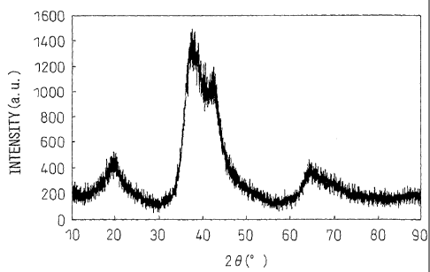
FIG. 1 is an X-ray diffraction chart for a furnace
cooled Zn-45 atm%Mg-5 atm%Ca alloy.
FIG. 2 is an X-ray diffraction chart of a thin strip
sample of a Zn-45 atm%Mg-5 atm%Ca alloy obtained by the
single roll method.
FIG. 3 is an X-ray diffraction chart of a thin strip
sample of a Zn-50 atm%Mg-5 atm%Ca alloy obtained by the
single roll method.
FIG. 4 is an X-ray diffraction chart of the plated
surface layer of the No. 35 plated steel plate of Table
2.
FIG. 5 is an X-ray diffraction chart of the plated
surface layers of the Nos. 62 to 65 plated steel plates
of Table 6.
FIG. 6 is an X-ray diffraction chart of the Nos. (1)
to (10) alloys of Table 7.
FIG. 7 is an X-ray diffraction chart of the No. (11)
alloy of Table 8.
BEST MODE FOR CARRYING OUT THE INVENTION
The inventors, with the object of obtaining an
amorphous alloy based on, by mass%, a metal element
having a small atomic radius, reevaluated the
conventional findings for discovering alloy compositions
with large amorphous forming abilities and searched
through various combinations of metal elements.
CA 02657779 2009-01-14
= - 11 -
=
As a result, the inventors independently derived a
selection of component elements and rule by which the
compositions are related for alloy compositions
exhibiting a high glass forming ability.
When discussing the glass forming ability, the
general practice is to use the atomic radii of the
component elements and the liquid forming enthalpy of the
combinations of the elements.,
In the present invention, for the atomic radii, the
values described in U.S. Patent No. 6623566 were used,
while for the liquid forming enthalpies, the values
described in CALPHAD, Vol. 1, No. 4, pp. 341-359 (1977),
Pergamon Press (Appendix: pp. 353-359) were used. For
lanthanide elements not described in the Appendix (Ce to
Lu), the values of La, Y, and Sc described in the
Appendix (pp. 358) were used.
The liquid forming enthalpy shows the energy of the
system when forming a liquid, so a negative sign and
large absolute value means a low energy of the system
when forming a liquid and a stable liquid state. That is,
when an alloy has a liquid forming enthalpy which is
negative and large in absolute value, it means that even
if the temperature falls, the liquid state will be
stable.
An amorphous is a structure obtained by freezing the
atomic structure of a liquid. An alloy with a liquid
forming enthalpy which is negative and large in absolute
value has a stable liquid state down to a low
temperature, so is an alloy with a high glass forming
ability.
In this way, the liquid forming enthalpy is
convenient for estimating the glass forming ability, but
experimental data on the liquid forming enthalpy is
limited. There is also the defect that each measurer
differs in measurement method, measurement temperature,
and evaluation of error.
On the other hand the liquid forming enthalpy was
Mk 02657779 2011-06-07
- 12 -
TM
theoretically calculated by the Miedema group for most of
the combinations of binary alloys of the Periodic Table
(CALPHAD, Vol. 1, No. 4, pp. 341-359 (see 1977), Pergamon
Press). If using these calculated values as a database,
it is possible to obtain liquid forming enthalpies
evaluated by the same precision for a large number of
alloy systems. Therefore, the present invention also uses
these values.
Below, the rule unique to the present invention and
the features of the alloys with high glass forming
ability prepared in accordance with this rule will be
explained in detail.
Note that the glass forming ability of the
individual alloy compositions is sometimes discussed, but
the alloy glass forming ability can be easily confirmed
using a differential scanning calorimeter (DSC).
To confirm the alloy glass forming ability, the
single roll method etc. may be used to fabricate an
actual amorphous alloy and the Tg/Tm ratio (Tg: alloy
glass transition temperature (K) of the alloy, Tm: melting
point (K) of the alloy) may be measured.
The larger the Tg/Tm ratio (absolute temperature
ratio), the higher the glass forming ability. If the Tg/Tm
ratio is 0.56 or more, high pressure die-casting using a
copper casting mold may be used to fabricate a bulk
metallic glass.
When obtaining an amorphous alloy, utilizing the
difference in atomic radii of the component elements to
increase the strain energy in the alloy and make it hard
for the atoms to move in the liquid is effective for
increasing the glass forming ability. For this reason,
mixing three or more types of elements with large
differences in atomic radii is a common practice. The
present invention is also based on this common practice.
The elements are differentiated into the group of
elements A with atomic radii of less than 0.145 nm (small
atomic radius), the group of elements A with atomic radii
CA 02657779 2009-01-14
- 13
of 0.145 nm to less than 0.17 nm (medium atomic radius),
and the group of elements C with atomic radii of 0.17 nm
or more (large atomic radius).
In the present invention, the object is to find a
method for designing an alloy composition with a high
glass forming ability based on an atom with a low glass
forming ability and with a small atomic radius.
As the atom with the small atomic radius desired to
be used as the base, first elements having an atomic
radius of less than 0.145 nm are set as elements with a
small atomic radius in the present invention. The group
of elements with small atomic radii is made the "group of
7
elements A".
The group of elements A include, in addition to Be,
the Group V to Group XI elements of the Periods IV, V,
and VI, Al, Zn, Ga, or other metal elements, B, C, Si, P,
and the Group IV to Group XVI elements of the Period IV.
The inventors studied alloy compositions based on
elements of the group of elements A and having high glass
forming ability and as a result found that by making the
boundary value of the atomic radii between the group of
elements B with the medium atomic radii and the group of
elements C with the large atomic radii 0.17 nm and
combining with the elements of the group of elements A
the elements of the group of elements B and elements of
the group of elements C, an alloy composition with a high
glass forming ability can be obtained.
For this reason, the boundary value for
differentiating the group of elements B and the group of
elements C in atomic radius was made 0.17 nm.
Note that as disclosed in U.S. Patent No. 6623566,
from In (0.1659 nm) to Yb (0.17 nm), the atomic radius
changes greater compared with between other elements.
From this point as well, the inventors judged that
differentiating the groups of elements at 0.17 nm would
be suitable.
Due to this classification, the group of elements B
CA 02657779 2009-01-14
- 14 -
include Li, Mg, Sc, the Group IV elements, Pr, Nd, Pm,
and Tm in the lanthanide elements, the Group XII to Group
XVI elements of the Period V, Bi, and Po.
The group of elements C include Na, K, Rb, Cs, Ca,
Sr, Ba, Y, La, Ce, or other lanthanide elements not
included in the group of elements B, Ti, and Pb.
The elements belonging to the group of elements A
are defined as the "Group A elements" and similarly the
elements belonging to the group of elements B and group
of elements C are defined as the "Group B elements" and
"Group C elements". In the alloy of the present
invention, one or more elements are selected from each of
the Group A elements, Group B elements, and Group C
elements to form the alloy.
The conventional rule in selection of elements is to
design the composition of components using as the base
the group of elements having the largest atomic radii in
the component elements. As opposed to this, the rule in
selection of elements in the present invention is
characterized in that it is possible to design a
composition of components based on, by mass%, the group
of elements having the smallest atomic radii so as to
realize a bulk metallic glass.
As explained above, the inventors adjusted the
content of the metal elements forming the base by mass%,
but the composition of an amorphous alloy is usually
expressed by the atm% used. Below, the composition of the
amorphous alloy will be explained by atm%.
The basic composition of the amorphous alloy of the
present invention (invention alloy), to stably secure the
glass forming ability, is made a total content of the
Group A elements of 20 to 85 atm%, a total content of the
Group B elements of 10 to 79.7 atm%, and a total content
of the Group C elements of 0.3 to 15 atm%.
The Group A elements are the metal elements forming
the base (mass%). By atm%, 20 atm% or more is required.
However, if over 85 atm%, the alloy glass forming ability
CA 02657779 2009-01-14
- 15 -
,
remarkably falls, so the upper limit was made 85 atm%.
The content (total) of the Group B elements and the
content (total) of the Group C elements, to secure the
required glass forming ability, are made 10 to 79.7 atm%
and 0.3 to 15 atm% in relation with the content (total)
of the Group A elements.
That is, if any of the content of the Group A
=
elements, the content of the Group B elements, and the
content of the Group C elements becomes outside the above
range of composition, the balance of content among the
groups of elements is lost and the glass forming ability
falls.
Further, designating the elements with the greatest
content in the Group A elements, Group B elements, and
Group C elements (main elements) as the "element a",
"element b", and "element c", the ratio of the content of
the element a with respect to the total content of the
Group A elements, the ratio of the content of the element
b with respect to the total content of the Group B
elements, and the ratio of the content of the element c
with respect to the total content of the Group C elements
are all made 70 atm% or more.
If the ratio of content of the element a, element b,
and/or element c becomes less than 70 atm% in the group
of elements, the effect of the elements other than the
main elements in the group of elements on the glass
forming ability can no longer be ignored.
For example, if the ratio of content of elements
other than the main elements in the group of elements
becomes 30 atm% or more, precipitation of the individual
metal components or precipitation of new intermetallic
compounds easily occurs. If this precipitation occurs,
the alloy glass forming ability falls.
In terms of securing a stable glass forming ability,
the ratios of contents of the element a, element b, and
element c in the respective groups of elements are
preferably 85 atm% or more, more preferably 90 atm% or
CA 02657779 2009-01-14
- 16 -
more.
Further, in all combinations of two elements
selected from element a, element b, and element c, the
liquid forming enthalpy must be negative. If even one
combination of the element a, element b, and element c of
all of the combinations of elements is a combination with
a positive liquid forming enthalpy, the glass forming
ability falls.
In the present invention, by selecting Zn or Al as
the element a and selecting the element b and element c
from the above-mentioned group of elements B and group of
elements C, it is possible to obtain an amorphous alloy.
Selecting Mg and Ca as the element b and element c
is preferable in terms of improving the corrosion
resistance of the alloy while maintaining the glass
forming ability, but the contents of Mg and Ca differ
somewhat, depending on the content of the Zn or Al
(element a), in the ranges of 10 to 79.7 atm% and in the
range of 0.3 to 15 atm%.
Note that, even when the element a is the base by
mass%, the Mg content sometimes exceeds the content of
the element a by atm%.
Zn or Al (element a) is preferably included in an
amount of over 30 atm% so as to secure a stable glass
forming ability. If Zn or Al (element a) is over 30 to 85
atm%, Mg (element b) is preferably less than 10 to 69.7
atm% and Ca (element c) is preferably 0.3 to 15 atm%.
Zn or Al (element a) is more preferably 40 to less
than 64.7 atm%, but in this case, Mg (element b) is made
over 35 to 59.7 atm% and Ca (element c) is made 0.3 to 15
atm%.
Ca has a relatively large effect on the glass
forming ability, so Ca (element c) is preferably made 2
to 15 atm%.
When making Ca (element c) 2 to 15 atm%, Zn or Al
(element a) is preferably 40 to 85 atm% and Mg (element
b) is preferably 10 to 55 atm%.
CA 02657779 2009-01-14
- 17 -
,
When making Ca (element c) 2 to 15 atm%, Zn or Al
(element a) is more preferably 40 to 70 atm%, but in this
case, Mg (element b) is preferably 20 to 55 atm%.
When making Ca (element c) 2 to 15 atm%, Zn or Al
(element a) is more preferably 40 to less than 63 atm%.
In this case, Mg (element b) is over 35 to 55 atm%.
Even when selecting Zn as the element a and
selecting Al as the element a' of the next greatest
content after Zn (element a), a superior glass forming
ability can be secured.
Zn and Al are relatively close in melting point and
atomic radius, so in the invention alloy, Zn and Al can
be handled together.
Further, Zn and Al, in the equilibrium diagram, do
not form an intermetallic compound with a high melting
point comprised of the two elements of Zn and Al at all,
so no rise in the melting point is caused and no dross-
like substance covering the molten metal surface is
formed at the time of melting the alloy.
Further, in the case of an alloy with Zn as its
base, addition of a small amount of Al lowers the melting
point of the alloy itself. Unless instantaneously cooling
the alloy down to the glass transition temperature, in an
alloy designed for formation of an amorphous phase, a
drop in the alloy melting point is preferable for
increasing the glass forming ability.
However, as can be deduced from the Al-Zn
equilibrium diagram, there is an optimum value to the
amount of addition of Al. The ratio of Zn in the total of
Zn and Al is preferably 70% or more, more preferably 80%
or more.
In this case, it is preferable to make Zn (element
a) and Al (element a') a total of over 30 to 85 atm%, to
make Mg 10 to less than 69.7 atm%, and to make Ca 0.3 to
15 atm%.
The total of Zn (element a) and Al (element a') is
more preferably 40 to less than 64.7 atm%, but in this
CA 02657779 2009-01-14
=
- 18 -
case, Mg is made over 35 to 59.7 atm% and Ca is made 0.3
to 15 atm%.
Ca has a relatively large glass forming ability, so
Ca (element c) is preferably made 2 to 15 atm%.
When making Ca (element c) 2 to 15 atm%, the total
of Zn (element a) and Al (element a') is preferably 40 to
85 atm% and Mg (element b) is preferably 10 to 55 atm%.
When making Ca (element c) 2 to 15 atm%, the total
of Zn (element a) and Al (element a') is more preferably
40 to 70 atm%. In this case, Mg (element b) is preferably
to 55 atm%.
When making Ca (element c) 2 to 15 atm%, the total
of Zn (element a) and Al (element a') is more preferably
40 to less than 63 atm%. In this case, Mg (element b) is
15 over 35 to 55 atm%.
Further, preferably the total of Zn (element a) and
Al (element a') is made 20 to 30 atm%, Mg is made 67.5 to
79.7 atm%, and Ca is made 0.3 to 2.5 atm%.
The reason for defining the concentration of Ca low
20 in the above range of composition will be explained
later.
The reason why the glass forming ability rises in
the range of composition of the present invention is not
necessarily clear, but the inventors discovered that in
the range of composition of the present invention, a
stable three-way intermetallic compound comprised of the
element a, element b, and element c is easily formed.
The fact that when a stable intermetallic compound
is formed between elements forming the alloy and the
change in enthalpy due to the formation of the
intermetallic compound is large, the glass forming
ability becomes higher is known empirically.
Therefore, it is fully conceivable that formation of
a three-way intermetallic compound would play some role
in improvement of the glass forming ability.
In a composition with a low glass forming ability
outside the range of composition of the present
CA 02657779 2009-01-14
=
- 19 -
invention, binary intermetallic compounds comprised of
combinations of two types of elements from the element a,
element b, and element c are preferentially formed.
Therefore, the inventors considered that there is a
good chance that a composition preferentially forming a
three-way intermetallic compound would improve the glass
forming ability.
Further, the inventors guessed that even with binary
intermetallic compounds, intermetallic compounds
comprised of extremely large numbers of atoms and having
complicated crystalline structures, for example, Mg51Zn20,
Mg17A112, etc. contribute to a certain degree to the
improvement, of the glass forming ability.
Among these groups of elements, if in the range of
less than 30 atm% of the total of the contents of the
groups of elements, it is also possible to add an element
different from the element a, element b, and element c.
The added element becomes an obstacle hindering movement
of the atoms in the molten alloy at the time of melting
the alloy, exhibits an effect increasing the strain
energy in the alloy at the time of solidification, and
improves the glass forming ability somewhat.
In the conventional understanding, even among the
Group A elements, Al and Zn make design of an alloy
composition with a high glass forming ability difficult
and make an Al- or Zn-based bulk metallic glass or
amorphous alloy difficult to obtain.
However, if designing the alloy composition
selecting Al or Zn as the element a along with the rule
of the present invention, it is possible to form a bulk
metallic glass or amorphous structure even with an alloy
with a high Al or Zn concentration. This was found by
research of the inventors.
However, when applying the rule of the present
invention to an Al-Mg-(Ca,La,Y) system, care is required.
In the case of an alloy comprised by selecting Al as the
element a, Mg as the element b, and Ca, La, or Y as the
CA 02657779 2009-01-14
=
=
- 20 -
element c, severe bubbling occurs near a melting
temperature of 500 to 800 C.
In particular, when La or Y is included, bubbling is
severe and the viscosity is high, so the work of melting
and solidifying the alloy becomes difficult.
The cause of this bubbling is not elucidated, but it
is believed that this is related to the fact that the
melting temperature of Al is near the ignition points of
Mg or Ca, La, and Y.
If melting, then slowly cooling an Al-Mg-(Ca,La,Y)-
based alloy, the time for the alloy to pass through 500
to 800 C becomes long and the amount of bubbling
increases. This alloy becomes semimolten in state at 500
to 800 C and is high in viscosity, and the gas formed is
not released to the outside, so the volume increases and
the result becomes a closed pore foam material.
This alloy becomes uneven in heat conductivity due
to the pores formed. Even if the glass forming ability is
high, it is believed that the volume fraction of the
amorphous phase is small.
Therefore, when using these alloys for the
fabrication of an amorphous alloy, a large cooling rate
becomes necessary for suppressing the formation of pores.
For example, to suppress bubbling, the alloy is cooled to
a ribbon shape.
If the thickness becomes 50 m or less, the cooling
rate is sufficiently obtained and an amorphous thin strip
is easily obtained. Further, it is possible to form a
thin film to suppress the bubbling, so use as a plating
is suitable as the application of this alloy.
In addition, if using high pressure die-casting, it
becomes possible to fabricate a bulk amorphous structure
with no pores up to a thickness of about 1 mm.
Zn has no possibility of bubbling. This is believed
to be due to the fact that Zn has a melting point of a
low 410 C and a low viscosity at 500 to 800 C. Further, Zn
CA 02657779 2009-01-14
- 21 -
=
is believed to be effective for raising the ignition
temperature of Mg or Ca. For this reason, in the alloy of
the present invention, there is no possibility of
ignition until the melting temperature.
An amorphous alloy of the present invention in which
Al or Zn is selected as the element a, Mg is selected as
the element b, and Ca is selected as the element c can
sufficiently secure an glass forming ability even without
using Y, La, or another expensive rare earth element. For
this reason, the amorphous alloy of the present invention
is preferable economically and industrially.
In a Zn-based alloy, by the addition of Mg or Ca, it
is possible to improve the glass forming ability while
raising the corrosion resistance, so addition of Mg
and/or Ca is suitable from this point as well.
In an Al-Mg-Ca-based alloy and Zn-Mg-Ca-based alloy
of the present invention, by making the content of Al or
Zn over 30 to 85 atm%, making the content of Mg 10 to
less than 69.7 atm%, and making the content of Ca 0.3 to
15 atm%, it becomes possible to obtain a much higher
glass forming ability.
In the case of an Zn-Mg-Ca system, in the
equilibrium state of the above range of composition,
Ca2Mg5Zn13 (three-way intermetallic compound) is formed in
an 80% or more volume fraction and the glass forming
ability becomes extremely high.
However, in a composition outside of the above range
of composition, MgZn2 or another binary intermetallic
compound or an Mg or Zn solid metal phase is formed in a
20% or more volume fraction and the glass forming ability
becomes somewhat low.
In a range of composition where the total of Zn
(element a) and Al (element a') is 20 to 30 atm%, Mg is
67.5 to 79.7 atm%, and Ca is 0.3 to 2.5 atm%, if the
cooling rate is relatively large, Mg51Zn20 is formed.
Note that cooling rate being relatively large means
not the quenching method such as with the single roll
ak 02657779 2011-06-07
- 22 -
method, but for example a cooling rate of an extent of
immersion of a small amount of a molten metal in water
for rapid cooling.
In particular, near an Zn of 28 atm% and Mg of 72
atm%, this intermetallic compound is easily formed.
When the Ca concentration is low, this intermetallic
compound is easily formed, but when the Ca concentration
is high, the blending ratio becomes unbalanced and
formation becomes difficult, so the upper limit of the Ca
concentration is made 2.5 atm%.
The inventors believed that when the Ca
concentration is low, Ca atoms are filled in the cavities
formed by the regular
icosahedral structures and,
as a result, binary intermetallic compounds probably
perform the same role as three-way intermetallic
compounds.
When fabricating an amorphous alloy by the quenching
solidification method, the melting point and viscosity of
the alloy are preferably low. The melting point and
viscosity are correlated. If coMparing the viscosities of
molten alloys held at the same melting temperature, in
general ones with low melting points have low
viscosities.
In the case of a high viscosity, when using the
single roll method to fabricate an amorphous thin strip,
nozzle clogging is caused. Even with high pressure die-
casting, insufficient filling or other defects are
caused.
In the case of a Zn-Mg-Ca system, preferably the
composition of the alloy of the present invention is
further limited by (a) making Zn (element a) over 30 to
85 atm%, Mg (element b) 10 to less than 69.7 atm%, and Ca
(element c) 0.3 to 15 atm%, by (b) making Zn (element a)
to less than 64.7 atm%, Mg (element b) over 35 to 59.7
35 atm%, and Ca (element c) 0.3 to 15 atm%, by (c) making Zn
(element a) 40 to 85 atm%, Mg (element b) 10 to 55 atm%,
and Ca (element c) 2 to 15 atm%, by (d) making Zn
CA 02657779 2009-01-14
- 23 -
=
(element a) 40 to 70 atm%, Mg (element b) 20 to 55 atm%,
and Ca (element c) 2 to 15 atm%, or by (e) making Zn
(element a) 40 to less than 63 atm%, Mg (element b) over
35 to 55 atm%, and Ca (element c) 2 to 15 atm%.
Due to this limitation, it becomes possible to
fabricate an alloy having a low melting point, a low
viscosity even at a melting temperature near 550 C, and
having a composition advantageous to the production of an
amorphous structure.
Further, an Zn-Mg-Ca-based alloy in the above range
of composition has a relatively high glass forming
ability and enables an amorphous phase to be easily
obtained.
Further, an alloy in said range of composition has a
melting point near 520 C or below it, which is lower than
ignition point of Mg (the ignition point of Mg in this
composition being around 570 C due to the inclusion of Zn
and Ca), so can be melted without concern about the
ignition point. It is therefore advantageous in this
point.
In the above range of composition, in the
equilibrium state, in addition to Ca2Mg5Zn13, Zn3Mg7 and Mg
are formed. The inventors believe that the fact that
these products form eutectic crystals is a factor for
maintaining the melting point low and raising the glass
forming ability.
In the case of an Al-Mg-Ca system, like with a Zn-
Mg-Ca system, preferably the composition of the alloy of
the present invention is further limited by (a) making Al
(element a) over 30 to 85 atm%, Mg (element b) 10 to less
than 69.7 atm%, and Ca (element c) 0.3 to 15 atm%, by (b)
making Al (element a) 40 to less than 64.7 atm%, Mg
(element b) over 35 to 59.7 atm%, and Ca (element c) 0.3
to 15 atm%, by (c) making Al (element a) 40 to 85 atm%,
Mg (element b) 10 to 55 atm%, and Ca (element c) 2 to 15
atm%, by (d) making Al (element a) 40 to 70 atm%, Mg
CA 02657779 2009-01-14
- 24
(element b) 20 to 55 atm%, and Ca (element c) 2 to 15
atm%, or by (e) making Al (element a) 40 to less than 63
atm%, Mg (element b) over 35 to 55 atm%, and Ca (element
c) 2 to 15 atm%.
Due to this limitation, it becomes possible to
fabricate an alloy having a low melting point, a low
viscosity even at a melting temperature near 600 C, and
having a composition advantageous to the production of an
amorphous structure.
At the above low melting point, formation of Mg17A112
comprised of Mg and Al (melting point: 460 C) is believed
to greatly contribute to this.
In an Al-Mg-Ca system, the bubbling becomes a
problem, but if an alloy in the above range of
composition, it is possible to shorten the time for
passing the bubbling temperature region at the time of
solidification, so it is possible to relatively easily
cast an amorphous alloy while suppressing bubbling. This
is advantageous in fabricating an amorphous alloy.
In a (Zn+A1)-Mg-Ca system (however, amount of Zn >
amount of Al) as well, as explained above, the
composition of the alloy of the present invention is
limited by (a) making Zn (element a)+Al (element a') over
to 85 atm%, Mg (element b) 10 to less than 69.7 atm%,
25 and Ca (element c) 0.3 to 15 atm%, by (b) making Zn
(element a)+Al (element a') 40 to less than 64.7 atm%, Mg
(element b) over 35 to 59.7 atm%, and Ca (element c) 0.3
to 15 atm%, by (c) making Al (element a) 40 to 85 atm%,
Mg (element b) 10 to 55 atm%, and Ca (element c) 2 to 15
30 atm%, by (d) making Al (element a) 40 to 70 atm%, Mg
(element b) 20 to 55 atm%, and Ca (element c) 2 to 15
atm%, or by (e) making Al (element a) 40 to less than 63
atm%, Mg (element b) over 35 to 55 atm%, and Ca (element
c) 2 to 15 atm%.
Further, on the other hand, in a (Zn+A1)-Mg-Ca
system (where amount of Zn > amount of Al), the
composition of the alloy of the present invention is
CA 02657779 2009-01-14
= - 25 -
limited by (f) making Zn (element a)+Al (element a') 20
to 30 atm%, Mg (element b) 67.5 to 79.7 atm%, and Ca
(element c) 0.3 to 2.5 atm%.
By these limitations, it becomes possible to
fabricate an alloy having a low melting point, having a
low viscosity even at a melting temperature near 550 C,
and having a composition advantageous for production of
an amorphous structure.
Further, in the Al-Mg-Ca-based alloy, Zn-Mg-Ca-based
alloy, and (Zn+A1)-Mg-Ca-based alloy of the present
invention, if including as part of the Group A elements
at least one of Au, Ag, Cu, and Ni in an amount of 0.1 to
7 atm%, the glass forming ability is improved.
With a content of less than 0.1 atm% with respect to
the composition as a whole, there is no effect of
improvement of the glass forming ability. When the
content is 3 to 4 atm%, the glass forming ability is
improved the most.
However, if the content exceeds 7 atm%, individual
metal components precipitate or binary intermetallic
compounds including additive atoms preferentially
precipitate and the glass forming ability becomes
extremely low.
The alloy of the present invention is an alloy with
a high glass forming ability, so it is possible to use
the liquid quenching method to easily fabricate an
amorphous alloy.
Therefore, in the present invention, among the
production methods for raising the temperature of the
alloy to the melting point or more to achieve the molten
state once, then finally producing a solid product
(casting methods in the broad sense), the single roll
method and high pressure die-casting or the casting
method using a copper casting mold are defined as liquid
quenching methods.
The liquid quenching methods in the broad sense
include almost all casting methods, but among these, the
CA 02657779 2009-01-14
= - 26 -
=
single roll method and high-pressure die casting are
production methods enabling mass production of bulk
products.
However, these methods of production are slower in
cooling rate compared with the atomizer method or piston
anvil method etc., so are methods of production requiring
a relatively high glass forming ability.
The alloy of the present invention at least ,nables
the production of amorphous thin strip by the single roll
method. From the past, with an alloy enabling the
production of an amorphous thin strip by the single roll
method, it has been possible to produce a bulk metallic
glass by high pressure die-casting using a copper casting
mold.
As one embodiment of the present invention, there is
an amorphous alloy-plated metal material containing an
amorphous phase. As an alloy-plated metal material, a Zn-
based or Al-based alloy plated steel material is being
widely used in the automobile, home electric appliance,
building material, civil engineering, and other fields,
but up until now it was difficult to obtain an alloy of a
composition improving the glass forming ability in Zn-
based alloys or Al-based alloys. Therefore, in alloy
plating, there was never any plating having an amorphous
phase.
According to the present invention, in Zn-based
alloys and Al-based alloys, it is possible to obtain an
alloy of a composition with a high glass forming ability,
so it is possible to produce a Zn-based and Al-based
alloy-plated metal material including an amorphous phase.
As the method for fabrication of an amorphous alloy-
plated metal material, there are the electroplating
method, flame spraying method, vapor deposition method,
hot dip plating, etc. However, the invention alloy uses
at the minimum three types of elements, so if considering
the preferential precipitation of elements etc., it is
difficult to maintain the bath conditions for obtaining a
CA 02657779 2009-01-14
- 27 -
predetermined composition constant at all times in the
electroplating method. Therefore, the electroplating
method is a plating method with problems in stability of
production.
5. The flame spraying method and vapor deposition
method are inherently methods enabling high cooling
rates, but continuous operation is costly, so these
methods are not suitable for mass production.
In the flame spraying method or vapor deposition
method, if increasing the temperature of the substrate so
as to improve the adhesion of the plating layer, the
cooling rate becomes relatively smaller. However, if
using an invention alloy with a high glass forming
ability, it is possible to easily form an amorphous phase
without being restricted by the film-forming conditions.
As opposed to these methods, hot dip plating is a
method for which a large cooling rate is difficult to
obtain, but the productivity is extremely high, so it is
an optimal method for obtaining an amorphous alloy-plated
metal material using an alloy enabling a high glass
forming ability according to the present invention.
Further, the alloy of the present invention has a
melting point of 350 to 800 C, so hot dip plating can be
preferably used.
If using hot dip plating to fabricate the amorphous
alloy-plated metal material of the present invention, the
Sendzimir method, flux method, preplating method, or all
other hot dip plating may be used.
Among the alloys of the present invention as well,
when plating an alloy having a somewhat low glass forming
ability, to obtain a greater amount, by volume fraction,
preferably 50% or more, of an amorphous phase, the
plating thickness has to be reduced.
With the usual cooling method, the closer to the
surface, the higher the cooling rate, so if making the
plating thickness thinner, the amorphous phase volume
fraction increases.
CA 02657779 2009-01-14
- 28 -
When plating an alloy having a somewhat low glass
forming ability, right after the plating, -150 C low
temperature nitrogen gas right after evaporation of
liquid nitrogen is used to cool the plating layer.
Further, the plating layer can be directly dipped
into liquid nitrogen to further speed the cooling rate
for cooling.
The metal of the substrate of the plated metal
material of the alloy of the present invention is not
particularly limited to any specific metal, but when
using hot dip plating to plate an invention alloy, a
metal with a higher melting point than the melting point
of the plating alloy is necessary.
When using a metal forming an oxide film on the
surface which is extremely stable and poor in reactivity
with the plating metal as the substrate (for example, an
Al-Mg-Ca-based substrate), the preplating method etc. has
to be applied in some cases.
When selecting a steel material as the substrate of
the alloy-plated metal material of the present invention,
the grade of the steel material is not particularly
limited. Al-killed steel, ultralow carbon steel, high
carbon steel, various high strength steels, Ni,Cr-
containing steels, etc. may be used.
\ 25 The steelmaking method, hot rolling method, pickling
method, cold rolling method, or other pretreatment of the
steel material is not particularly limited.
From the viewpoints of the ease of hot dip plating,
cost performance as a material, etc., a steel material is
most preferred as the substrate of the present invention.
When selecting a copper material as the substrate of
the alloy-plated metal material of the present invention,
since the copper material and the Al-based alloy are
. close in melting points, it is unsuitable to select an
Al-based alloy as a plating metal.
When plating a Zn-based alloy on a copper material,
an intermetallic compound phase is easily formed with the
CA 02657779 2009-01-14
- 29 -
copper material, so the dipping time in the plating bath
is preferably made 3 seconds or less.
The volume of the amorphous phase in the plating
layer can be measured by cutting the plated metal
material at a plane vertical to the surface, polishing
and etching the cross-section, and observing the cross-
section of the plating layer by an optical microscope.
In the amorphous phase parts, no structure is
observed even with etching, while in the crystal phase
parts, structures due to crystal grain boundaries, sub-
boundaries, and deposits, etc. are observed.
Due to this, it is possible to clearly differentiate
between the amorphous phase parts and crystal phase
parts, so it is possible' to convert to the volume
fraction by the line segment method or image analysis.
When the structure is too fine and measurement by an
optical microscope is difficult, a thin section is
prepared from the cross-section of the plating layer and
observed by a transmission electron microscope and
similarly measured.
In the case of a transmission electron microscope,
it is possible to confirm an amorphous structure from the
halo pattern of the electron beam diffraction image in
the region where the structure is not observed.
In observation by an optical microscope, when the
structure is not observed at the entire surface or even
when there are parts where the structure is not observed
and there is a suspicion of coarse, strain-free crystal
grains, it is preferable to obtain thin sections for
electron microscope use and confirm that the electron
beam diffraction image has no diffraction spots and
exhibits a halo pattern and confirm that the structure is
.an amorphous phase.
For the volume fraction, for both an optical
microscope or an electron microscope, it is preferable to
observe 10 or more different fields, find the area ratios
by image processing by computer, and obtain the average
CA 02657779 2009-01-14
- 30 -
to convert to the volume fraction.
The alloy plating layers in the range of composition
of the present invention all exhibit corrosion
resistances of hot dip galvanized steel plate or more.
If the composition of components is the same, an
amorphous alloy plating is better in corrosion resistance
compared with a crystalline alloy plating. By including
an amorphous phase in a volume fraction of the plating
layer of 5% or more, the plating is improved in the
corrosion resistance.
This effect of improvement of the corrosion
resistance can be confirmed by a cyclic corrosion test,
electrochemical measurement, etc. For example, the
inventors evaluated the corrosion resistance of the
actual environment by a cyclic corrosion test (JASO M
609-91, 8 hr/cycle, wet/dry time ratio 50%, however,
using 0.5% saltwater as the saltwater) and as a result
that plated steel plate containing 5% or more of an
amorphous phase has less corrosion loss than crystalline
alloy plating of the same composition of components.
Further, in electrochemical measurement (in 0.5%NaC1
solution, vs Ag/AgC1), having an amorphous phase in the
plating layer results in a noble corrosion potential
compared with an alloy plating of the same composition
but only a crystal phase. Further, the corrosion current
density near the corrosion potential became small.
The effect of the amorphous phase on the corrosion
resistance appears remarkably when the amorphous phase is
present in a volume fraction of 50% or more.
This is believed to be due to the facts that there
are no crystal grain boundaries forming starting points
of corrosion and also Mg, Ca, or other components
improving the corrosion resistance are uniformly
distributed over the plating layer.
In crystalline plating, intermetallic compounds of
different compositions, single metal phases, alloy
phases, etc. are formed in the plating layer, so these
CA 02657779 2009-01-14
= - 31 -
=
form coupling cells, whereby corrosion is promoted.
However, in an amorphous alloy plating, originally
there is no intermetallic compound or other crystal phase
and the component elements uniformly distribute over the
plating layer, so such promotion of corrosion does not
occur.
The effect of improvement of the corrosion
resistance by the amorphous phase is generally remarkably
observed in a Zn-based alloy. With Zn, the solid solution
limit of Mg, Ca, or other additive elements improving the
corrosion resistance is small, so even if added in a
small amount, an intermetallic compound ends up being
easily formed.
=On the other hand, in an Al-based alloy, originally,
an Al-based alloy has a higher corrosion resistance
compared with a Zn-based alloy. The solute limit of Mg,
Ca, etc. is large, so an intermetallic compound is hard
to form.
In an amorphous alloy plating, if the surface layer
(layer within 2 m from surface of plating layer) becomes
a complete amorphous phase not containing any crystal
phase, the corrosion resistance is remarkably improved
and, further, the fine projections on the surface due to
the crystal phase are eliminated.
As a result, it is possible to obtain a plated metal
material with a high reflection surface in which surface
projections of a level relating to the reflection of
electromagnetic waves smoothed. This high reflectance
plated metal material is particularly useful as a heat
reflecting material.
To confirm the existence of an amorphous phase of
the surface layer, the thin film X-ray diffraction method
irradiating X-rays at the plating surface at a low
incident angle and measuring the diffracted X-rays by a
collimating optical system is suitable.
In the present invention, the "plating" for which
diffraction peaks due to a crystal phase cannot be
CA 02657779 2009-01-14
= - 32 -
detected using Ka-X-rays of copper under conditions of an
incident angle of 1 is defined as the "plating" of a
single amorphous phase of the surface layer. The heat
reflectance of the metal material having this "plating"
becomes a level higher than a crystal phase plated metal
material.
Note that "diffraction peaks due to a crystal phase"
means diffraction peaks significantly higher in X-ray
intensity than the background level and not broad. For
example, it indicates a peak having a peak height of a
50% or more of the background intensity and having a half
value width of the peak of 1 or less.
EXAMPLES
The present invention will be explained in further
detail while showing examples.
(Example 1)
Zn, Mg, and Ca metal reagents (purity 99.9 mass% or
more) were mixed and melted using a high frequency
induction heating furnace in an Ar atmosphere at 600 C,
then furnace cooled to obtain a Zn: 50 atm%, Mg: 45 atm%,
Ca: 5 atm% chemical composition furnace cooled alloy.
This furnace cooled alloy had an X-ray diffraction
chart as shown in FIG. 1. With this composition, as an
equilibrium phase, the intermetallic compound Ca2Mg5Zn13 is
formed.
The alloy of said composition was used to fabricate
a thin strip sample by the single roll method. The thin
strip sample was fabricated using a Nisshin Giken single
roll apparatus (RQ-1).
A quartz crucible having a slit-shaped aperture (0.6
mmx20 mm) at its bottom end was charged with the alloy to
0.1 kg and heated. The alloy was held at a temperature
100 C higher than the melting point of 346 C (619K) for 5
minutes, then the molten alloy was ejected on to a Cu
roll (roll diameter 300 mm) rotated at a peripheral speed
CA 02657779 2009-01-14
- 33 -
of 50 m/sec by a pressure of 0.03 MPa.
The distance between the aperture and roll surface
at the time of ejection was 0.2 mm. The obtained thin
strip sample had a width 3 to 10 mm, a length of 50 to
100 mm, and a thickness of about 10 to 20 m.
The prepared thin strip sample had an X-ray
diffraction chart by the thin film X-ray diffraction
method as shown in FIG. 2. As shown in FIG. 2, the peak
of the crystal phase disappeared and a halo pattern
distinctive to an amorphous phase was detected.
(Example 2)
Zn, Al, Mg, and Ca metal reagents (purity 99.9 mass%
or more) were mixed and melted using a high frequency
induction furnace in an Ar atmosphere at 600 C, then
furnace cooled to obtain the a furnace cooled alloy of a
chemical composition of Zn:45 atm%, Mg:50 atm%, and Ca:5
atm%.
This alloy was used to fabricate a thin strip sample
by the single roll method. For fabrication of the thin
strip sample, a single roll apparatus (RQ-1) made by
Nisshin Giken was used.
A quartz crucible having a slit-shaped aperture (0.6
mmx20 mm) at its front end was charged with 0.1 kg of the
alloy and heated. The alloy was held at a temperature of
100 C higher than the melting point 373 C (646K) for 5
minutes. The molten alloy was ejected at a pressure of
0.03 MPa on a Cu roll (roll diameter 300 mm) rotated at a
peripheral speed of 50 m/sec.
The distance between the aperture and roll surface
at the time of ejection was 0.2 mm. The obtained thin
strip sample had a width of 3 to 10 mm, a length of 50 to
100 mrn, and a thickness of about 10 to 20 m.
An X-ray diffraction chart of the fabricated thin
strip sample by the thin film X-ray diffraction method is
shown in FIG. 3. As shown in FIG. 3, the peak of the
crystal phase disappeared and a halo pattern distinctive
CA 02657779 2009-01-14
* - 34 -
to formation of an amorphous phase was detected.
(Example 3)
Different metals (purity 99.9 mass% or more) were
mixed in predetermined amounts and melted using a high
frequency induction heating furnace in an Ar atmosphere
at 600 to 1100 C, then were furnace cooled to obtain
alloys of the chemical compositions of Nos. 1 to 48 shown
in Table 1 and Table 2 (continuation of Table 1).
The chemical compositions of the different alloys
were determined by ICP (inductively-coupled plasma)
spectrometry using acid solution dissolving swarf
obtained from the alloys.
To fabricate amorphous samples of the alloys of the
above chemical compositions, the single roll method was
used.
Using an apparatus the same as the one used in
Example 1, quartz crucibles having slit-shaped apertures
(0.6 mmx20 mm) at their front ends were charged with 0.1
kg amounts of these alloys. The alloys were held at
temperatures 80 to 200 C higher than the melting points
(Tm) for several minutes. The molten alloys were ejected
at pressures of 0.02 to 0.03 MPa on Cu rolls (roll
diameters 300 mm) rotated at peripheral speeds of 50
m/sec.
The distances between the apertures and roll
surfaces at the time of ejection were 0.2 mm. The
obtained amorphous thin strips had widths of 3 to 10 mm,
lengths of 50 to 100 mm, and thicknesses of about 10 to
20 m. Thin strip samples were fabricated from these.
. .
Table 1
A B C
C
,
Amorphous phase fraction 1
Tm Tg
Rare earth
No.Tg/Tm by high pressure clie a
Ag Al Au Cu Ni Si Zn Li Mg Sn
Ca = La Y (K) (IQ s (La,Y used)
cating s
S
. .
1 ' 65 , 25 10 1041 645
C)(0.62) A(69%) -
_ _
_ ,
2 50 45 , 5 1019 622
0(0.61) A(66%) -
3 80 10 10 942 537 ' 0(0.57)
0(79%) -
4 82 10 8 928 529
0(0.57) 0(80%) -
_ . .
0
80 12 8 924 527 0(0.57)
0(80%) -
6 80 12 8 , 1045 585
C)(0.56) 0(75%) . Yes o
,
n.)
,
7 75 5 12 8 1039 613
0(0.59) 0(88%) Yes (5)
in
_
. .--.1
8 79 112 8 1030 587
C)(0.57) C)(79%) Yes .--.1
- - . .
9 1 79 õ 12 8 1028 586
C)(0.57) 0(80%) Yes .--.1
li)
. 75 32 12 8 1025 605 0(0.59)
()(87%) Yes N.)
.
I o
11 80, 10 . 10 . , ,
944 , 538 C)(0.57) C)(79%) o
n
I li)
12 75 18 7 843 481
0(0.57) õ 0(80%) - v 1
o
13 75 20 5 798 , 487 ,
C)(0.61) (g(90%) Yes Co H
._(iiI
_
14 70, 20 10 , 955 563
C)(0.59) (g(90%) - e H
II.
---'I
70 : 25 , . 5 766 460 0(0.6)
0(93%) - X
=
16 65 25 , 10 , , 946 568
C)(0.6) (D(94%) -
. ,
_
17 60 30 ' 10 949 560
C)(0.59) 0(89%) -
16 50 , 45 , 5 775 457
C)(0.59) 0(88%) -
. . , _
_
19 45. . õ 50 5 780 460
C)(0.59) ()(88%) -
. ,
40 55 5 781 461 CD(0.59)
0(88%) -
21 80 13 , 7. 809 - 396
A(0.49) - -
,
.
22 75 17 . 1 7 , 812 398
A(0.49) - -
23 70 23 õ 7 , 745 380
A(0.51) - -
24 5 65 237 , , 736 383
0(0.52) - -
, .
1 69 23 7 742 386_ 0(0.52) -
-
/ - --,
Table 2 (Continuation of Table 1)
A B C
c
High pressure die cast
1
Tm Tg
Rare earth
No. Tg/Tm
amorphous phase a
Ag Al Au Cu Ni Si Zn Li Mg Sn Ca La
y (K) aq a,a,Y used)
fraction
s
S
_
..
.
26 1 , 69 23 7 742 , 386 0(0.52)
- -
27 65 25 10 õ 739 , 384
0(0.52) - -
28 60 35 5 736 390 0(0.53)
-
_
29 55 40 5 663 345 C1(0.52)
-
_
n
30 50 47 3 618 340 A(0.55)
-
_
.
31 õ 50 45 5 619 340 A(0.55)
- _ o
.
I N.)
32 , õ 50 45 5 623 343 0(0.55)
- - m
-,-
n in
33 * = 50 45 5 769 415 0(0.54)
- - v .--.1
.-A
- _
34 45 45 10 652 359 0(0.55)
- .--.1
li)
. - .
35 45 50 , 5 646 355 0(0.55)
- - e N.)
,
36 40 50 10 645 355 0(0.55)
- - x o o
.
= i li)
37 40 55 , 5 644 354 0(0.55)
- - (1)
-
=
38 5 50 40 , 5 671 362 0(0.54)
- - Co H
39 3 52 40- , 5 667 367 0(0.55)
- - H
11.
-
40 2 53 40 , 5 665 352
0(0.53)(0.53) - - - 1
,
' 41 0.2 54.8 _ . 40 5 665 = 352 0(0.53)
- '
_ .
42 0.05 54.95 40 5 663 345 0(0.52)
-
_
43_ 50 25 25 746 366
x(0.47) - -
44 90 5 5 783 - -
- - C
_
45 40 35 25 745 358 x(0.48)
- -
, .
e
46 60 . 20 20 1078 474
x(0.44) , - -
- .
x
47 65 25 10 998 - -
- -
48 50 . 45 5 896 - -
- -
_
_
CA 02657779 2009-01-14
- 37 -
,
The obtained thin strip samples were used to obtain
X-ray diffraction charts by the X-ray diffraction method.
In the alloys of the present invention composition, that
is, Nos. 1 to 42, diffraction peaks due to the crystal
phases were not detected. Only halo patterns due to the
amorphous phases were detected.
On the other hand, in Nos. 43 to 48 not included in
the range of composition of the alloy of the present
invention, broad diffraction peaks showing that the
crystal phases remained were detected. Even if
fabricating thin strip samples by the single roll method,
it was learned that the amorphous forming abilities were
low with the crystal phases remaining.
These thin strip samples were buried in resin,
polished by emery paper, buffed, then etched. An optical
microscope was used to measure the areas of the crystal
phases of the cross-sections of the thin strip samples.
In Nos. 43, 45, and 46, amorphous phases were
detected but the amorphous volume fractions were less
than 50%. Further, Nos. 44, 47, and 48 were completely
crystalline.
About 5 mg amounts of cut pieces of the thin strip
samples were taken, analyzed by a differential scanning
calorimeter (DSC), and measured for Tg/Tm ratio. The rate
of temperature rise was 40 C/min.
In Table 1 and Table 2, samples with a Tg/Tm ratio of
less than 0.49 are indicated as "x", with a ratio of 0.49
to 0.52 as "A", with a ratio of 0.52 to 0.54 as "D", with
a ratio of 0.54 to 0.56 as "0", with a ratio of 0.56 to
0.58 as "0", and with a ratio of 0.58 or more as
Among the prepared alloys, alloys with a Tg/Tm ratio
of 0.56 or more (Nos. 1 to 20) were used to fabricate
quenched solidified pieces using a copper casting mold
and high pressure die-casting. These were fabricated by
holding the alloys at temperatures 30 to 100 C higher than
the melting point for several minutes and ejecting them
CA 02657779 2009-01-14
- 38 -
at pressures of 0.07 MPa. The obtained quenched
solidified pieces had a size of 30x30 mm and thickness of
2 mm.
These solidified piece were used for X-ray
diffraction analysis in the plate state, and it could be
confirmed that the surface layers of the solidified
pieces were completely amorphous.
The fabricated 2 mm thickness solidified pieces were
cut at their center parts, polished by emery paper,
buffed, then etched. An optical microscope was used to
measure the areas of the crystal phases of the cross-
sections of the solidified piece.
Among the alloys with low amorphous forming
abilities, there were ones where a crystal phase was
detected at the centers of the cross-sections of the
solidified pieces.
In the Al-based alloys, ones with a Tg/Tm ratio of
0.6 or more gave almost complete single amorphous phases.
In ones with a ratio less than 0.58, when the Tg/Tm ratios
became smaller, the ratios of the crystal phase in the
cross-sectional area became greater.
If the Tg/Tm ratios differ by 0.01, the amorphous
volume fractions in the cross-sectional area differ by
around 3 to 5%.
In Table 1 and Table 2, samples with a volume
fraction of 50 to 70% are indicated as "A", with 70 to
90% as "CD", and with 90% or more as
The alloys of the invention examples were all higher
in glass forming ability compared with the alloys of the
comparative example alloys. Further, in the Zn or Al-
based alloys of the present invention, by utilizing Mg
and Ca, it became possible to get amorphous forming
abilities and form amorphous alloys without regard as to
the rare earth elements. By not using any rare earth
elements, it becomes possible to lower the alloy costs.
Among these as well, alloys containing Zn or Al in
CA 02657779 2009-01-14
- 39 -
amounts of 20 to 85 atm%, Mg in amounts of 10 to 79.7
atm%, and Ca in amounts of 0.3 to 15 atm% have higher
Tg/Tm ratios and more superior amorphous forming abilities
compared with Zn-Mg-Ca-based alloys or Al-Mg-Ca-based
alloys outside these ranges of composition.
Alloys to which Au, Ag, Cu, Ni, etc. are added in
amounts of 0.1 to 7 atm% have further higher Tg/Tm ratios
and have more superior amorphous forming abilities
compared with alloys to which these are not added.
(Example 4)
Alloys of the compositions shown by Nos. 3 to 5 and
Nos. 11 to 42 of Table 1 and Table 2 and Nos. 51 to 61 of
Table 3 and Table 4 (continuation of Table 3) were hot
dip plated on metal materials.
The metal materials used for the plating substrates
were cold rolled steel plate of a plate thickness of 0.8
mm, copper plate of a plate thickness of 0.5 mm, equal
angle steel of a thickness of 10 mm and a length of a
side of 10 cm, and hot rolled steel plate of a plate
thickness of 10 mm.
The cold rolled steel plate and copper plate were
cut into 10 cmx10 cm specimens, the equal angle steel was
cut into specimens of 10 cm in the longitudinal
direction, and the hot rolled steel plate was cut into
squares of 10 cmx10 cm for use as plating substrates.
Nos. 56 to 61 are comparative examples, that is, all
crystalline A1-20 atm%Mg-10 atm%Ca plated steel plate
(No. 56), Zn-45 atm%Mg-5 atm%Ca plated steel plate (No.
57), Zn-11 atm% Al-plated steel plate (No. 58),
galvanized steel plate (No. 59), A1-25 atm%Zn plated
steel plate (No. 60), and A1-10 atm%Si-plated steel plate
(No. 61).
.._ ----.
Table 3
A B C
Heat c
, 0 , -
Amorphous
Steel -
Amorphous Corro- reflect- 1
Amount of
phase of Heat
mater-Tm Tg phases
voluae sion ance 1
No. - Tg/Tm deposition
surface reflec
ial Ag Al Au Cu Ni Si Zn Li Mg Sn Ca La Y (K) (K)
g/m?' fraction of layer of resis-
tance after heat a
class plated
layer tance treatment s
plating
,
_
(20CPC,24h) s
. _____________________ _
,
3 80 10 10 942 537 0(0.57) 10
0(90%) , C) C) 0.84 0.72
I , _____
4 62 10 8 928 529 C7(0.57) 10
C)(90%) C) 0 0.83 0.73
.
" 80 12 8 924 527 0(0.57) 10
0(90%) 0 0 0.83 0.72
11 80 , 10 10 , 944 538 , 0(0.57) 15
10(90%) , C) 0 0.86 0.81 0
12 ' 75 18 7 843 481 0(0.57) 15
0(90%) 0 0 0.83 0.79
o
13 75 20 5 798 487 0(0.61) 30
0(83%) C) C) 0.87 0.77 n.)
(3)
14 70 20 10 ___ 955 563 0(0.59) 20
0(97%) CD 0 0.84 0.8 in
.--.1
..--.1
70 25 5 . 766 460 0(0.6) 20 0(100%) 0
() 0.83 0.65 .--.1
. - -
l0
16 65 25 ., _ 10 946 568 0(0.6)
40 0(92%) , 0 0.83 0.78 n.)
. _
'0 I
17 60 30 10 949 560 0(0.59) 45
C)(90%) , 0 0.84 0.72 o
Cold , _ ____________________ _
_ n I 0
18 , roll- 50. 45 5 _ , 775 457 0(0.59)
15 0(97%) 0 0 0.84 0.65 v ko .
19 ed 45 50, 5 780 460 C)(0.59) 40
0(91%) (7 Ã5) 0.84 0.65 CL. a.
-
CD I-'
. ___________________________
---.16- steel 40 55 5 781 461 0(0.59)
40 0(90%) C) 0 0.84 0.65 e 1
'
----- plate - . _____________________________ - _
x I H
21 80 13 7 . 809 ' 396 A(0.49) 25
54%) CD C) 0.81 0.41 F1'
_ A(
,
22
. 75 17 1 7 812 398 A(0.49) 25
A(56%) C) 0 0.81 0.44
23: 70 23 7 745 380 A(0.51) 25
A(65%) 0 0 0.8 0.43
_
24 5 , 65 23 7_ . 736 383 0(0.52)
25 C)(71%) 0 _ C) 0.6 0.4
_ -
1.. 69 23 7 742 386 0(0.52) 25
0(70%) C) 0.8 0.4
_
26 1 69 23 7 742 386 0(0.52) 25
0(70%) () C) 0.81 0.4
1 _
-
. .
.
28 60 35 5 736 390 0(0.53) 25
0(78%) C) 0 0.82 0.4
_
29 55 40 5 663_ 345 0(0.52) 25 _
C)(72%) C) C) 0.77 0.4
. _
3050 47 , 3 618 340 0(0.55) 50
A(64%) 0 0 0.83 0.4
. . L I ,
.
_
Table 4 (Continuation of Table 3)
A B C Anount
Amorphous Heat C
Amorphous Corrc-
Steel of
phase of Heat reflectance 1
phases volume
No. material Tm Tg Tg/Tm depcsi-
surface sion reflecta after heat a
Ag Al Au Cu Ni Si Zn Li Mg Sn Ca La Y 0 (lc) tion
fraction of resis -
class
layer of nce treatment s
, ,
plated layer tance
g/nr
plating (200PC,24h) s
31 50 45 5 619 340 0(0 55)
25 0(90%) 0 CD 0.81 0.4
.
32 50 45 5 623 343 0(0.55) 60
0(75%) CD CD 0.76 0.39
, -
33 50 45 5' 769 415 -0(0.54)
90 ' A(69%) () C) 0.77 0.38
_
34 45 45 10 652 359 -<C>(0.55)
25 0(89%) () C) 0.76 0.35
-
35 45 50 5 _ 646 õ 355 70(0.55)
25 õ C)(90%) C) CD 0.82 0.4 0
36 40 50 10 645 , 355 0(0.55) 20
' 0(90%) C) C) 0.79 0.42 o
37 40 55 = 5 644 354 0(0.55) 25
0(90%) C) 0 . 0.82 0.4 , n.)
I d)
38 5 50 40 _ 5 671 362 -0(0.54)
60 A(62%) C) CD 0.79 0.4 n in
.--.1
39 3 52 40 5 . 667 367 -0(0.55)
30 C)(89%) C) 0 0.8 0.4 v
-
. _
li)
40 111111111 2 II 53 I 40 ..õ 5 665 352 0(0.53) 25
C)(75%) C) 0 0.8 0.4
õ
-
41 0.2 54.8 40 5 665 352 0(0.53) 25
C)(75%) c) CD 0.8 0.4 e n.)
o
-
- - x I o
42
plate Copper 11111111 0.05 54.95 40 5 663 345 0(0.52) 25 _
C)(70%) C) CD 0.77 0.4 ko
50
_
51 45 5 619 340 0(0.55) 30
A(69%) C) CD 0.77 0.25
.
I
, - .
i-
111111Hot roll-.11111 50 45 5 619 340 0(0.55)
120 A(69%) C) 0 0.78 0.4
_ . ,
-
steel
80 1111 10 10 944 529 C)(0.56) 50
A(68%) C) 0.85 0.81
plate
54 Equal 1.1111.1111111 50 45 5
-
C) C) 0.78 0.41
sangle teel 80 10 10 944 529 C)(0.56) 70
A(66%) C) CD 0.85 0.8
56 70 20 10. 955 - - 15
x(0%) x 0 0.35 0.72
57 Cold _________________ 50 = 45 5 619 - - 25 ,
x(0%) , x A 0.74 0.36 C
58 rolled 11 69_ _ 625 , - , - 25 ,
x(0%) x A 0.74 0.52
-
e
59 steel - 100 688 - -
25 x(0%) x x 0.72 0.43
_ _
x
. -
plate 75 25 860 -- 15 x(0%)
x C) 0.76 0.72
_________________________________________ _ _
61 90 10 _, - 861 - -
20 x(0%) x _ 0 0.69 0.66
CA 02657779 2009-01-14
- 42 -
The cold rolled steel plate and copper plate were
degreased, then plated by a batch type hot dip plating
apparatus made by Rhesca. The cold rolled steel plate was
annealed at a dew point -60 C N2-5%H2 at 800 C for 60
seconds.
After annealing, the plate was cooled to the bath
temperature and dipped in the plating bath. The copper
plate was raised in temperature in N2-5%H2 to the bath
temperature and immediately dipped into the plating bath.
The temperature of the plating baths was
standardized at the melting point of the plating alloy +
50 C in accordance with the plating alloy composition. Air
wiping was used to adjust the coating masses, then the
cooling start temperature was set at the melting point +
1 to + 10 C and the plates were cooled by -150 C low
temperature nitrogen gas. The amorphous volume fractions
changed according to the plating compositions and the
coating masses.
Further, the plated metal materials of the
comparative examples comprised of alloys of the
compositions of the present invention, but comprised of
crystal phases (No. 56, No. 57) were air wiped, then air-
cooled.
The equal angle steel and hot rolled steel plate
were degreased, pickled by sulfuric acid, then hot dip
plated using a crucible furnace by the flux method. Right
after plating, these were cooled by liquid nitrogen.
For Al-based hot dip plating, first plating by a Zn-
0.2%Al plating bath was performed by the usual flux
method, then a plating bath of the target composition was
used for second plating.
In this case, the amount of deposition becomes the
total of the amounts of deposition of the first and
second platings, but part of the first plating dissolves
at the time of the second plating, so the amount of
deposition was made the total amount of the plating
CA 02657779 2009-01-14
- 43 -
finally present on the substrate.
Said alloy-plated metal materials were used for the
evaluation test explained below. The amount of deposition
of the plating was measured by the loss of mass upon
dissolving the plating layer in an acid. The alloy
components in the plating was assayed by ICP
(inductively-coupled plasma) spectrometry using acid
solutions dissolving swarf obtained from the alloys.
However, in hot dip plating, the alloy layer easily
grows, so the plating layer was separately dissolved by a
pickling time of 80% of the pickling time required for
measurement of the amount of deposition to prepare a
sample for analysis of the composition of the plated
surface layer.
As a result, in the alloy composition and plating
composition used, the error was within 0.5 atm%. It could
be confirmed that there was no deviation in the
composition.
For the amorphous volume fraction of the plating
layer, two thin sections for transmission electron
microscope use were taken at each of the positions of the
thickness of the plating layer of the test piece divided
into five equal parts, image analysis using computer was
used to measure the area ratios of the amorphous regions
in each of the fields, and the average value of the area
ratios of the amorphous regions in all fields were used
as the amorphous volume fraction.
If plating by the same amount of deposition, if the
Tg/Tm ratio is different by 0.01, the amorphous volume
fraction differs by 3 to 5%.
In Table 3 and Table 4, a sample with an amorphous
volume fraction of the plating layer of less than 50% is
indicated as "x", one of 50 to 70% is indicated as "A",
one of 70 to 90% is indicated as "0", and one of 90% or
more is "g".
The mode of formation of the amorphous phase at the
CA 02657779 2009-01-14
- 44 -
surface layer of the plating layer was judged by
obtaining an X-ray diffraction chart at an incident angle
of 1 by a thin film X-ray diffraction apparatus of a
parallel optical system using the Ka-X-rays of Cu and
observing for the presence of a diffraction peak due to a
crystal phase.
An X-ray diffraction chart at the plating layer
surface layer of the No. 35 plated steel plate in Table 2
is shown in FIG. 4. As shown in FIG. 4, due to the
amorphous phase of the plating layer surface layer, the
peak of the crystal phase disappears and a halo pattern
distinctive to the amorphous phase is detected.
A peak having a peak height of 50% or more of the
background intensity and having a half value width of
that peak of 1 or less is defined as the diffraction peak
due to the crystal phase. A sample with no diffraction
peak due to the crystal phase detected was judged to have
a surface layer which is completely amorphous and was
indicated by "0", while a sample with a diffraction peak
due to the crystal phase detected was judged to have a
crystal phase present at the surface layer and was
indicated by "x".
The corrosion test was performed based on the salt
spray test (SST) described in JIS-Z-2371.
The corrosion loss after running a test with a
saltwater concentration of 10 g/liter for 3000 hours was
evaluated. A sample with a corrosion loss of less than 2
g/m2 was indicated as Ø, with 2 to 5 g/m2 was indicated
as "0", and with 5 g/m2 or more was indicated as "x".
Further, all plating samples were measured for heat
reflectance. The heat reflectances of the plating layers
were measured using a heat reflectance measurement
apparatus.
This measurement apparatus is comprised of a light
projector using a solar simulation lamp (150W, 17V made
by Philips Japan) as a light source, an infrared region
CA 02657779 2009-01-14
- 45 -
integrating sphere (diameter of 51 cm, inner metal
diffusion surface made by Labshere), and a prototype
radiometer using a thermopile (MIR-1000Q made by
Mitsubishi Yuka) as a sensor.
An "infrared integrating sphere" is a device
comprised of a sphere plated with gold on its inner
surface to make it a high reflectance diffusion surface
and provided with a light entry port and an inside
observation port.
The pseudo sunlight emitted from a lamp was
condensed by a concave mirror and emitted toward a sample
in the integrating sphere. Reflection at the sample
surface occurs in all directions, but is condensed at the
radiometer by multiple diffusion and reflection inside
the integrating sphere. The output voltage of the
radiometer is proportional to the intensity of the entire
reflected light.
The DC output voltage Vo of the radiometer at the
time when not emitting light is measured. First, light
was illuminated at a gold vapor deposited mirror (05 mm)
with a heat reflectance deemed to be 1 and the output
voltage Vm of the radiometer was measured. Next, the
output voltage Vs when firing light at a plating sample
(05 mm) was measured.
Using the measurement values Vo, Vm, and Vs, the
heat reflectance r was found from the equation r-(Vs-
Vo)/(Vm-Vo). Each sample was measured 10 or more times
and average used as the heat reflectance of that sample.
The measurement results are shown in Table 3 and Table 4.
Further, each sample was heat treated in an Ar
atmosphere at 200 C for 24 hours, then again measured for
heat reflectance. The results are also shown in Table 3
and Table 4.
The corrosion resistance of the plated metal
material due to the alloy of the composition of the
present invention was better in all cases compared with
CA 02657779 2009-01-14
- 46 -
the comparative metal materials. Further, the Zn-based
metal material of the present invention has a higher heat
reflectance compared with the Zn-based comparative metal
material, further the Al-based metal material of the
present invention has a higher heat reflectance than an
Al-based comparative metal material.
In particular, the Al-based metal material of the
present invention can maintain a high heat reflectance
even after heat treatment.
(Example 5)
The Nos. 27 to 31, 35, and 37 alloys were used and
hot dip plated. After hot dip plating, they were cooled
by liquid nitrogen gas to fabricate plated steel plates
with different volume fractions of amorphous phases. When
fabricating crystalline plated steel plates, hot dip
plating, then air cooling are sufficient.
The volume fraction of the amorphous phase can be
adjusted by dipping the steel plates in the plating bath,
then lifting up the steel plates and adjusting the steel
plate temperature at the point when starting the cooling
by liquid nitrogen gas.
That is, by making the steel plate temperature at
the point when starting the cooling by liquid nitrogen
gas a temperature 1 to 10 C lower than the melting point
of the plating bath, part of the plating layer is
crystallized and the rest is maintained in the
supercooled state.
If performing the liquid nitrogen air cooling in
this semicrystalline state, the part in the supercooled
state becomes the amorphous phase as it is. The amount of
crystallization becomes greater the lower the cooling
start temperature and the greater the longer the holding
time at that temperature.
Plated steel plates with different volume fractions
of amorphous phases were fabricated by controlling the
cooling start temperature and holding time.
The fabricated plated steel plates were subjected to
CA 02657779 2009-01-14
- 47 -
a cyclic corrosion test. The corrosion test consisted of
21 cycles of the method based on automobile standards
(JASO M 609-91, 8 hours, wet/dry time ratio-50%).
However, for the saltwater, 0.5% saltwater was used.
The corrosion resistance was evaluated by corrosion
thickness reduction converted from the density and the
corrosion mass loss after corrosion.
A corrosion thickness reduction of less than 1 m
was evaluated as "CD" (very good), 1 to 2 m as "CD"
(good), 2 to 4 m as "0" (fair), and 4 m or more as "x"
(poor). Table 5 shows the corrosion resistance of the
alloy plated steel plates.
Table 5
_ _
Arrorphous
Amount
A of phases
-
Tm Tg
.volurre Corrosion
No. (K) Tg/Tm deposi-
fracticn resistance
tion
Ag Al Au Cu Ni Si Zn Li Mg Sn Ca La Y ,,of plated
gMC layer
25 0 C71%)
27 65 25 10 739 384 0(0.52) 25
x(27%) 0
25 x(0%)
25 0(76%)
0
28 60 35 5 736 390 0(0.53) 25
x(25%) 0
25 x(0%)
25 0(72%) 0
29 55 40 5 663 345 0(0.52) 25
x(18%) 0
25 xmo 0
25 A(64%)
C)
30 50 47 3 618 340 0(0.55) 25
x(10%) 0
n xmo
25 C)(90%)
31 50 45 5 619 340 0(0.55) 25
x(25%) 0
25 x(0%) 0
25 C)(90%)
35 45 50 5 646 355 0(0.55) 25
x(3%) 0
n xmo 0
25 0(90%)
C)
37 40 55 5 644 354 0(0.55) 25
x(5%) 0
25 x(0%) 0
As shown in Table 5, plated steel plate containing
an amorphous phase in a volume fraction of 5% or more in
the plating layer is superior in corrosion resistance to
plated steel plate having a crystalline plating layer of
the same composition of components. Further, plated steel
plate containing an amorphous phase in a volume fraction
CA 02657779 2009-01-14
. =
- 48 -
of 50% or more in the plating layer is more superior in
corrosion resistance.
(Example 6)
Cold rolled steel plates of plate thicknesses of 0.8
mm (substrates) were dipped in baths of the plating
compositions shown in Table 6 to fabricate surface
treated steel plates.
The Mg, Zn, Ca, and other necessary component
elements were adjusted to predetermined compositions,
then a high frequency induction furnace was used to melt
them in an Ar atmosphere to obtain alloys.
Cutting swarf was taken from each of the prepared
alloys, then the cutting swarf was dissolved in acid. The
solution assayed by ICP (inductively-coupled plasma)
spectrometry to confirm that the fabricated alloy matched
the composition shown in Table 6. This alloy was used as
a plating bath.
The cold rolled steel plates (plate thickness 0.8
mm) were cut into 10 cmx10 cm specimens which were then
plated by a batch type hot dip plating apparatus made by
Rhesca. The bath temperature of the plating bath was
500 C. Air wiping was used to adjust the coating masses,
then the specimens were immersed in 0 C water.
The formation of an amorphous phase at the surface
layer of the plating layer was judged by using an X-ray
diffraction apparatus using the Ka-X-rays of Cu for
measurement of the diffraction chart and judging the
existence of a halo pattern.
For plated steel plates judged to have amorphous
phases, to find the volume fraction of the amorphous
phase quantitatively, the plated steel material was cut
along the cross-section, then was polished and etched and
the plating layer of the surface was observed by an
optical microscope (X1000).
The area ratios of the amorphous phase were found by
image processing by computer for 10 or more different
CA 02657779 2009-01-14
- 49 -
fields and were averaged to obtain the volume fraction.
The fabricated plated steel plate was subjected to a
cyclic corrosion test. The corrosion test consisted of 21
cycles of the method based on automobile standards (JASO
M 609-91, 8 hours, wet/dry time ratio-50%). However, for
the saltwater, 0.5% saltwater was used. The corrosion
resistance was evaluated by corrosion thickness reduction
converted from the density and the corrosion mass loss
after corrosion.
A corrosion thickness reduction of less than 1 pm
was evaluated as "0" (very good), 1 to 2 pm as "0"
( (good), 2 to 4 pm as "0" (fair), and 4 pm or more as "x"
(poor). Table 6 shows the corrosion resistance of the
fabricated alloy plated steel plates.
FIG. 5 shows X-ray diffraction charts of the plated
surface layers of No. 62 to 64 in Table 6. In each
diffraction chart, a halo pattern was detected, showing
the existence of an amorphous phase.
Table 6
A B c
kaount Amorphous
-
Prcduc- of phases
volume Corro-sion
No. tion deposi
Ag Al Au Cu Ni Si mLi Mg Sn Ca La y method -tion fraction resis-tance
in2 of
plated
g , layer
Water
( 62 30 65 5
cooling 10 C)(91%) C)
_ _
Water
63 1.0 29 65 5 10
0(90%) C)
cooling
- . .
Water
64 2.8 27 65.2 5 20
0(90%) C)
cooling
-
Water
65 4.4 25 65.6 5 20
0(91%) CD
cooling
Water
66 1 24 70 5 20 0(96%) 0
cooling
_ _ _
Water
67 2 23 70 5 20 0(94%) 0
cooling
Water
68 4 21 70 5 20
0(90%) C)
cooling
_
,
Water
69 1 W 68.3 0.7 M
x(23%) 0
cooling
_ , _
'
Water
70 1 30 67.5 1.5 n
x(2590 0
. _
cooling
_ _ _ . .
.
Water
71 1 32 64.7 2.3 M
x(16%) 0 .
I cooling
1
(Example 7)
Zn, Al, Mg, and Ca metal reagents (purity 99.9 mass%
or more) were mixed and melted using a high frequency
CA 02657779 2009-01-14
¨ SO -
induction furnace in an Ar atmosphere at 600 C, then
furnace cooled to obtain the alloys of the compositions
shown in Table 7.
These alloys were remelted in the atmosphere, then 1
cc amounts of the melts were scooped up and immersed in a
liter water tank.
The formed phases of the rapidly cooled alloy
surfaces were identified by X-ray diffraction. FIG. 6
shows the X-ray diffraction charts. Depending on the
10
differences in thickness and cooling rates, some crystal
phases were mixed in, but in each case a halo pattern was
detected. Note that (1) to (10) in the figure show the X-
ray diffraction charts of Nos. (1) to (10) in Table 7.
Table 7
Prcduc-
A Tm Tg
No. tion
Tg/Tm
(K) (K)
rethod
Ag Al Au_ Cu Ni Si Zn Sri_ Ca La Y
Water
(1) 1 30 65 4
cooling 633 335 0(0.53)
Water
(2) 3 29 64 4
g 633 335 0(0.53)
000lin
Water
(3) 528 63
4 633 335 0(0.53)
- - _ cooling
Water
(4) 7 27 62 4
cooling 623 330 0(0.53)
Water
(5) 1 32 63 4
cooling 633 335 0(0.53)
Water
(6) 8 28 60_
4 643 341 0(0.53)
cooling
Water
(7) 1 35 60 4
cooling 643 347 0(0.54)
_
Water
(8) 1 40 55 4
cooling 643 347 0(0.54)
water
(9) 2 39 56 3
cooling 643 347 0(0.54)
Water
(10) 2 46 49 5
cooling 673 370 0(0.55)
(Example 8)
Zn, Al, Mg, and Ca metal reagents (purity 99.9 mass%
or more) were mixed and melted using a high frequency
induction furnace in an Ar atmosphere at 600 C, then
furnace cooled to obtain the alloys of the compositions
shown in Table 8. These alloys were used as plating
alloys.
Cold rolled steel plates (plate thickness 0.8 mm)
CA 02657779 2009-01-14
- 51 -
were cut into 10 cm x 10 cm samples, then plated by a
batch type hot dip plating test apparatus made by Rhesca.
The bath temperature of the plating bath was 500 C. Air
wiping was used to adjust the amount of deposition, then
the samples were immersed in water of 0 C.
The phase formed at the surface layer of the plating
layer was analyzed by measuring the X-ray diffraction
chart by an X-ray diffraction apparatus using Ka-X-rays
of Cu. To confirm the presence of the amorphous phase,
the plated steel material was cut along its cross-
section, then was polished and etched and the plating
layer of the surface was observed by an optical
microscope (X1000).
For the amorphous volume fraction of the plating
layer, two thin sections for transmission electron
microscope use were taken at each of the positions of the
thickness of the plating layer of the test piece divided
into five equal parts, image analysis using a computer
was used to measure the area ratios of the amorphous
regions in each of the fields, and the average value of
the area ratios of the amorphous regions in all fields
were used as the amorphous volume fraction.
The fabricated plated steel plates were subjected to
a cyclic corrosion test. The corrosion test consisted of
21 cycles of the method based on automobile standards
(JASO M 609-91, 8 hours, wet/dry time ratio=50%).
However, for the saltwater, 0.5% saltwater was used. The
corrosion resistance was evaluated by corrosion thickness
reduction converted from the density and the corrosion
mass loss after corrosion.
Samples with a corrosion thickness reduction of less
than 1 m were evaluated as "0", of 1 to 2 m as "0", of
2 to 4 m as "0", and of 4 m or more as "x". Table 8
shows the corrosion resistances of the fabricated alloy
plated steel plates.
FIG. 7 shows an X-ray diffraction chart of No. (11)
CA 02657779 2009-01-14
- 52 -
in Table 8. From the figure, it will be understood that
the plating layer contains Mg51Zn20 (formed at the time of
water cooling).
Table 8
Amorphous
A Arount
of
- - - P
Tm Tg
Coxo
No. Tg/Tmdeposi-
tritc
(K) (K) fraction
resis-
Ag Al Au Cu Ni Si Zn Li Mg Sn Ca La Y tion nethod
gAtt2 of plated
tance
layer
Water
(11) 5 23 69.8 2.2 623336 0.54
25 14% cool- C)
ing
- -
Water
(12) 5 20 73.0 2 623336 0.54
25 8% cool- 0
ing
INDUSTRIAL APPLICABILITY
By fabricating an alloy (invention alloy) by the
composition of the present invention, a bulk metallic
glass or amorphous alloy can be obtained from an alloy
composition by which a bulk metallic glass or amorphous
alloy could not be obtained in the past.
Up until now, with alloys with low amorphous forming
abilities, even if amorphous phases could be obtained,
the shapes were limited to powders or thin strips etc.
Bulk metallic glass could not be fabricated.
By using the invention alloy, it becomes possible to
obtain an alloy with a high glass forming ability and
becomes possible to produce a bulk metallic glass by high
pressure die-casting high in productivity and using a
metal casting mold enabling production of bulk shapes.
According to the present invention, as stated above,
a bulk metallic glass can be produced. Further, even in
systems of components considered difficult to obtain an
amorphous phase with in the past, an amorphous phase can
be produced. Therefore, the present invention expands the
applications of amorphous phases and contributes broadly
to the development of industry.
For example, even in Al alloy plating, Zn alloy
plating, and further Zn+Al alloy plating for which
formation of an amorphous phase had been impossible in
the past with hot dip plating, the alloy components of
the present invention enables formation of an amorphous
CA 02657779 2009-01-14
- 53 -
alloy plating layer even with hot dip plating.
The alloy of the present invention plating, with the
same amount of deposition, is better in corrosion
resistance than even hot dip galvanized steel plate.
Further, the amorphous alloy plating, with the same
amount of deposition, is better in corrosion resistance
than even a crystalline alloy plating.
The alloy of the present invention plating can be
widely applied to automobiles, buildings/housing, etc. It
improves the lifetime of members and
contributes to the effective utilization of resources,
reduction of the environmental load, reduction of labor
and costs in maintenance, etc. Therefore, the present
invention greatly contributes to the growth of industry.
Further, an amorphous alloy plating has a better
surface smoothness and higher light and heat reflectance
compared with a crystalline plating. If using this for
roofing and siding, the high level of its heat
reflectance enables the rise in surface temperature to be
prevented, so the rise in temperature indoors can be
suppressed and a reduction of the insulation load and
energy savings can be greatly contributed to.
The amorphous alloy plating of the present invention
can be broadly applied addition to reflecting plates of
electrical heaters, reflecting plates of high brightness
lighting, and other members requiring a high reflectance.
Through the improvement of the reflectance and the
provision of reflecting materials less expensive than the
past, the present dnvention greatly contributes to the
=
growth of industry.