Note: Descriptions are shown in the official language in which they were submitted.
WO 2008/014048 CA 02657837 2009-01-14 PCT/US2007/069601
ASH FLUIDIZATION SYSTEM AND METHOD
BACKGROUND OF THE INVENTION
(1) Field of the Invention
[0001] The present invention generally relates to a system for preventing
dust
build-up in ductwork. More particularly, the present invention relates to a
system that
uses the injection of air to re-entrain or fluidize ash in flue gas flowing
through the
ductwork of a selective catalytic reduction (SCR) system.
(2) Description of the Related Art
[0002] Selective catalytic reduction (SCR) systems are commonly applied
to
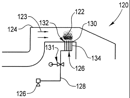
utility and industrial combustion units to reduce NOx emissions. In an SCR
system,
ammonia or the like is injected into a flue gas. The flue gas injected with
ammonia is
passed through a catalyst where chemical reactions occur to convert NOx
emissions to
elemental nitrogen and water. The presence of a catalyst is generally required
to
accelerate the chemical reactions because SCR systems typically operate at
relatively
low temperatures, which may slow or prevent the chemical reactions. Commonly
used catalysts include a vanadium/titanium formulation, zeolite materials, and
the
like.
[0003] Many of the installations place the SCR reactor in high dust
locations
before the particulate collection system. Careful attention is paid to the
design of the
ductwork and SCR reactor to avoid dust deposition. The catalyst is designed
specifically to withstand the erosion and potentially poisonous effects of the
fly ash.
The ductwork velocities are chosen to ensure the fly ash remains entrained at
the
design point, because ash drop out in the ductwork is undesirable.
[0004] However, it is common for such systems to experience dust deposition in
some locations within the ductwork under certain circumstances. The reduction
in
gas velocity through the ductwork experienced when the combustion unit is
operated
at reduced loads is the main cause of dust deposition. It could also be caused
by
environmental changes in the operating of the unit, for example, operating
with lower
excess air, or different fuels. The most common points for deposition are dead
legs in
the ductwork and in the ductwork just upstream of the SCR inlet hood.
1
WO 2008/014048 CA 02657837 2009-01-14 PCT/US2007/069601
[0005] FIGS. 1 and 2 provide an example of dust build-up and resulting
plugging
of a SCR system 20 from ash accumulation. FIG. 1 shows a portion of SCR system
20 when the combustion unit is operating at a low load 22. SCR system 20 is
typically located between a steam generator outlet (not shown) and a pre-
heater inlet
(not shown). As a flue gas stream 21 flows through a duct 24, fly ash is
typically
present in the flue gas stream. A catalyst 26 is housed in SCR system 20
within duct
24 and is subjected to the full concentration of fly ash as the flue gas
stream 21 passes
through it. Catalyst 26 is typically covered by screens 28 to capture fly ash
before it
reaches the catalyst channels (not shown).
[0006] SCR system 20 is sized to receive flue gas stream 21 when the
combustion
unit (not shown) is operating at a full load. When the combustion unit (not
shown) is
operated at a low load 22, duct 24 has less flue gas passing through it. The
velocity of
flue gas stream 21 is therefore reduced greatly. This reduction in velocity
can lead to
dust deposition. As flue gas stream 21 flows through duct 24, a fly ash 30
accumulates and settles in a dust pile 32. Due to the design of duct 24, dust
pile 32
normally occurs just upstream of an SCR inlet hood 34.
[0007] Referring now to FIG. 2, when SCR system 20 is operating at a full load
36, the velocity of flue gas stream 21 increases back to the design velocity.
As the
velocity is increased to accommodate full load 36, fly ash 30 that has
accumulated in
dust pile 32 may re-entrain suddenly causing an avalanche 38 of the fly ash to
fall
onto catalyst 26. As a result, channels (not shown) within catalyst 26 may
become
plugged and the efficiency of SCR system 20 reduced. The pressure drop across
SCR
system 20 may also increase.
[0008] Typically, the only measures taken to prevent the build-up of dust
piles involve the design of the ductwork. Generally, the shape of the entrance
to the
SCR inlet hood can be designed such that the velocity through this transition
piece is
constant at the design point. The result is ductwork with a sloping roof that
is at the
same time, expanding to match the SCR reactor cross-section. Bypass ducts are
protected either by equipping them with dampers to eliminate dead legs or by
making
the bypass duct have no shelf where ash can accumulate.
2
1 CA 02657837 2012-02-17
. 78396-89
[0009] These approaches have generally been proven unsuccessful. The
issue of dust deposition at the SCR inlet hood entrance and dead legs in the
ductwork still remains. Ash piles being sloughed off onto the catalyst beds as
the
combustion unit comes back up to full output load is an issue. Current
technology
offers little to address the potential of ash deposition at the SCR reactor
inlet area.
BRIEF SUMMARY OF THE INVENTION
[0010] One aspect of the invention is a system for fluidizing ash in a duct
of a
selective catalytic reduction system. The system includes a source for
generating
compressed air and an air injection header joined with the source and joined
with the
duct via one or more holes in the duct upstream of a catalyst. The air
injection
header is adapted to inject compressed air from the source to the areas of the
duct
prone to dust build-up.
[0011] Another aspect of the invention is a system for fluidizing ash in a
duct of
a selective catalytic reduction system. The system includes a duct, a
mechanism for
generating compressed air, and an air injection header joined with the
mechanism for
generating compressed air and joined with the duct upstream of a catalyst via
one or
more holes in the duct. The air injection header includes a sub-header joined
with a
plurality of injection lances. Each of the plurality of injection lances has
an end
nozzle. The air injection header is adapted to inject compressed air from the
mechanism for generating compressed air to the areas of the duct prone to dust
build-up.
[0012] Yet another aspect of the invention is a method for fluidizing ash in
a
duct of a selective catalytic reduction system. The method includes the
following
steps: providing a selective catalytic reduction system including a duct;
generating
compressed air; and injecting the compressed air to the areas of the duct
prone to
dust build-up via an air injection header and one or more holes in the duct
upstream
of a catalyst.
3
,
CA 02657837 2012-02-17
78396-89
[0013] Still another aspect of the invention is a selective catalytic
reduction
system comprising: a selective catalytic reduction system duct; a catalyst
positioned
within said duct; and an air injection header including a sub-header joined
with a
plurality of injection lances for injecting compressed air into said duct at a
position
upstream of said catalyst.
3a
WO 2008/014048 CA 02657837 2009-01-14 PCT/US2007/069601
BRIEF DESCRIPTION OF THE DRAWINGS
[0014] For the purpose of illustrating the invention, the drawings show a
form of the invention that is presently preferred. However, it should be
understood
that the present invention is not limited to the precise arrangements and
instrumentalities shown in the drawings, wherein:
FIG. 1 is a section view of a SCR system operating at a low load;
FIG. 2 is a section view of a SCR system operating at a full load;
FIG. 3A is a section view of a system according to one embodiment of the
present invention;
FIG. 3B is an isometric view of a sub-header according to one embodiment of
the present invention;
FIG. 4 is a section view of a nozzle according to one embodiment of the
present invention;
FIGS. 5A-5C are section views of a nozzle according to various embodiments
of the present invention; and
FIG. 6 is a section view of a manifold for use in an embodiment of the present
invention.
DETAILED DESCRIPTION
[0015] Referring now to the drawings in which like reference numerals indicate
like parts, and in particular, to FIGS. 3A and 3B, one aspect of the present
invention is
a system 120 for fluidizing ash to prevent the formation of a pile 122 of a
dust 123 in
a duct 124 of a selective catalytic reduction system (SCR). In system 120,
compressed air (not shown) from an air compressor 126 or a plant air supply
(not
shown) is injected to the areas of duct 124 prone to build-up of dust 123.
[0016] System 120 is typically located in an area of an SCR that is prone to
build-
up of dust 123, e.g., see FIGS. 1 and 2. An air injection header 128 is joined
with
duct 124 via one or more holes 130 in the duct. Air injection header 128
typically
includes a control valve 131 for controlling the flow of air and isolating
portions of
system 120 for maintenance. Air injection header 128 typically includes a sub-
header
132 joined with a plurality of injection lances 134. Each injection lance 134
generally
includes an end nozzle 136.
4
WO 2008/014048 CA 02657837 2009-01-14 PCT/US2007/069601
[0017] Referring now to FIGS. 4 and 5A-5C, end nozzle 136 may have a
mushroom cap 137, an angled end 138, a perforated end 139, or an open end 140
to
direct compressed air 141 in a particular direction. Mushroom cap 137 is
configured
to direct compressed air 141 flowing upwardly through lance 134 downwardly to
a
surface of duct 124 (see arrows). Angled end 138 is configured to direct
compressed
air 141 flowing upwardly through lance 134 in a particular direction, e.g.,
laterally
(see arrows). Perforated end 139 is configured to direct compressed air 141
flowing
upwardly through lance 134 in a particular direction, e.g., laterally. Open
end 140 is
configured to direct compressed air 141 flowing upwardly through lance 134 in
a
particular direction, e.g., upwardly. Mushroom cap 137, angled end 138,
perforated
end 139, and open end 140 may be configured, e.g., include screens or
appropriately
sized opening, to help prevent dust 123 from entering lance 134. It is
contemplated
that each type of end nozzle 136 may be adjustable or movable in myriad
directions,
e.g., telescopically, rotationally, vertically, horizontally, laterally,
axially, etc.
Plurality of lances 134 within a single sub-header 132 may include any
combination
of different types of end nozzles 136. Alternatively, as illustrated in FIG.
3B, at least
one of plurality of lances 134 may not include an end nozzle 136 and
compressed air
141 may flow upwardly through the lance and through hole 130 in duct 124.
[0018] Referring now to FIG. 6, in another embodiment, sub-header 132 includes
a
box-like manifold 142, which has a top 144, bottom 146, and sides 148 that
form an
interior cavity 150. Top 144 includes a top surface 152. Top surface 152 may
includes an outside lip 153 that rests on duct 124 to ensure an airtight fit
between sub-
header 132 and the duct. A plurality of injection lances 134 extend upwardly
through
top surface 152 and inject compressed air from interior cavity 150, which is
provided
by air injection header 128, to the areas of duct 124 prone to build-up of
dust 123.
One or more of plurality of injection lances 134 may be fitted with an end
nozzle 136.
Optionally, a motorized, pneumatic cylinder, or other mechanism 154 is joined
with
manifold 142 and is configured to move the manifold back and forth laterally
(see
arrow) to facilitate the movement of dust 123 in duct 124. It is also
contemplated that
such a mechanism may be used to move the manifolds in FIGS. 3A and 3B.
[0019] In use, air from compressor 126 is sent to an air injection header 128.
Air
injection header 128 feeds sub-headers 132 that in turn, feed air into
injection lances
7 8 3 9 6-8 9 CA 02657837 2012-12-07
134. Lances 134 extend into duct 124 through holes 130. The number of lances
134
may vary depending on the size of the SCR system. Each sub-header 128
typically
feeds multiple injection lances 134. At the end of each injection lance 134 is
typically
a nozzle 136. Air exiting each nozzle 136,causes dust 123 in the area of
nozzle 136 to
fluidize and become re-entrained in the flue gas flowing through duct 124.
[0020] The use of a compressed air system to eliminate ash deposition in an
SCR system offers advantages over prior art designs in that it eliminates dust
avalanches from falling onto the catalyst and plugging it. The present
invention has
the advantage of compressed air being an inexpensive medium and readily
available.
Maintenance needs for air compressors are well known, easy to perform, and
inexpensive. Additionally, because the nozzle design and header arrangement
can be
customized for plant specific requirements, aspects of the present invention
may be
easily modified.
[00211 Although the invention has been described and illustrated with respect
to
exemplary embodiments thereof, it should be understood by those skilled in the
art
that the foregoing and various other changes, omissions and additions may be
made
therein and thereto, without parting from the present invention.
6