Note: Descriptions are shown in the official language in which they were submitted.
CA 02658198 2009-03-12
AEROBIC RESISTANCE EXERCISE DEVICE
FIELD OF THE INVENTION:
This invention relates to exercise devices, and particularly to exercise
devices
which are intended to provide elastic resistance against which any group or
chosen
groups of muscles may be aerobically exercised. In particular, the present
invention
relates to exercise devices which are lightweight, portable, and inexpensive.
Moreover,
the present invention relates to exercise devices of the sort where the
lightweight device
may be quickly and easily fitted to, and removed from, the body of the user.
The
exercise device of the present invention is particularly useful for exercising
various
muscle and muscle groups, either together or separately, in the upper torso
(including
but not limited to, the chest, shoulders, or arm) and the lower torso
(including but not
limited to the legs and hips) of the user.
BACKGROUND OF THE INVENTION:
Resistance training strengthens and conditions the body. It reduces the loss
of
muscle mass while creating a stronger, toned body. Additional benefits include
providing improved posture, and aiding in the prevention of osteoporosis, or
the like.
Resistance exercises often involve lifting, pushing or pulling various objects
including
pulley systems, spring systems, elastics bands and tubing, and more
traditionally,
various weighted materials including free weights, plates, or the like.
-1..
CA 02658198 2009-03-12
Resistance training devices generally have limitations, or other drawbacks, in
that the number of muscles or muscle groups they can effectively
simultaneously impact
at one time, is limited. As a result, during a user's exercise routine, it may
be necessary
to change or add various components or other devices, in order to achieve the
full
impact of the training. Those added devices which can provide a comprehensive
workout, are typically very heavy, can result in equipment which requires an
excessive
amount of space, can be complex to set up and modify, and commonly require
foreign
objects, such as a pull bars, or the like, as part of the equipment setup. In
addition,
modification of the components during an exercise routine can be inconvenient,
as well
as being costly and/or time consuming.
Aerobic exercises are designed to be performed over a period of time as
opposed
to, say, weight lifting where the lifter exerts highly intense muscular
contractions but
only for a very short period of time. In contrast, aerobic exercises are
designed and
arranged to improve the fitness of various groups of muscles in the body, and
the
1 5 duration of the exercise is such is that glycogen or sugar will be
consumed by the body
muscles. Thus, in general, aerobic exercises are performed at a low to
moderate level of
intensity over a long period of time. For example, running over a long period
of time is
an excellent aerobic exercise, as opposed to sprinting which is not.
A number of benefits may be achieved over a period of time, including, for
example, strengthening the muscles which are involved in breathing,
strengthening and
enlarging the heart muscle to improve its pumping efficiency and reduce the
resting
heart rate, toning muscles throughout the body so as to improve overall
circulation and
reduce blood pressure, and to increase the total number of red cells in the
body's and
thereby to facilitate transport of oxygen throughout the body.
As noted, distance running is good form of aerobic exercise, but that usually
means running out of doors, possibly in inclement weather, or driving to a
gymnasium
or other exercise facility which is fitted with a track. Devices have also
been brought to
the market over the years which permit the user to perform aerobic exercises
in the
comfort and privacy of their own home. Such devices are either very simple,
such as a
skipping rope, or more typically are very expensive and/or complicated to
assemble and
-2-
CA 02658198 2009-03-12
use. Moreover, aerobic exercise devices are also usually fairly large and
heavy, and
take up considerable room.
Further, however, other aerobic exercise devices have been devised which are
essentially garments which are worn on the body of the user, and in many
respects
appear to be no different than a wet suit which is worn by a diver. That is,
those kind of
aerobic exercise devices require that the user insert his/her arms and legs
into the arms
and legs of the body suit.
The present inventor has unexpectedly discovered that a simple vest-like
garment can be supplied which encircles only a portion of the upper part of
the body of
the user, and is supported by the shoulders of the user, but which otherwise
does not
require that the arms or legs of the user be enclosed in sleeves or legs of
the garment.
Moreover, the exercise device of the present invention may be constructed with
mesh
material for the most part, so as to avoid overheating of the user's body and
to permit the
evaporation of perspiration therefrom, thereby keeping the body of the user
cooler than
1 5 it might be otherwise.
Further, a principal feature of the present invention is the fact that the key
element of the invention is a first long elastic member, the elastic strength
of which the
various muscle and muscle groups will work against. The long elastic member is
positioned on the back of the user in such a manner that it maintains its
configuration
and placement with respect to the back and hips of the user. When the elastic
member is
in tension, its length will change in that it will become longer. The elastic
memory of
the member will, however, attempt to restore the length of the elastic memory
to its
initial, at rest length, so that when the legs or hands of the user are moved,
such
movement will be against the resistance caused by the elastic memory and the
tensile
force which develops in the elastic member. That point alone distinguishes the
present
invention over the other similar aerobic exercise devices which have
heretofore been
available.
Additionally, however, a series of "rings" are strategically located on the
elastic
member that provide the following benefits, namely: facilitating the targeting
of various
muscle and muscle groups in the body from a readily accessible, central
location;
-3-
CA 02658198 2009-03-12
facilitate the addition of additional levels of resistance to the device; and
in some cases,
facilitate the modification of the tension or resistance encountered during a
specific
exercise.
DESCRIPTION OF THE PRIOR ART:
The nature of the prior art, and the constraints and restrictions thereof, are
illustrated by reference to the following three issue United States patents.
Karlik, in United States Patent 3,162,441 teaches a so-called universal
exerciser
whose purpose is to provide an exercising device which will permit a wide
variety of
exercises, particularly pulley exercises. The device comprises a plurality of
coil springs,
at the ends of which pulleys are arranged so as to accommodate a cord or other
flexible
line whose length remains constant throughout the performance of any exercise
which
can be done on the device.
Wehrell, in United States Patent 4,961,573 teaches an exercise harness which
is
designed to train and condition the user insofar as that user's arm speed,
endurance, and
power are concerned. This device comprises a harness which encircles the chest
of the
user, and provides, at the back thereof, independent pathways for two
independent
elastic cords. One end of each of the elastic cords is connected to a handle,
and the
other end is unattached. Two cleats are secured to a rigid or semi-rigid plate
which
extends across the back of the user or are attached to the two cords in a
manner so that
the path which each of the cords follows may be lengthened or shortened.
Wilkinson, in Britain United States Patent 5,186,701 teaches an aerobic
resistance exercise garment which is such as to effectively supplement
selected motion
exercises. This garment is required to be worn on the body and has anchor
members at
the hand or foot and which are connected one to another by an elastic
material. Here,
there are a plurality of cords which are independent one from another so that
each of the
arms and legs has its own respective cord associated therewith.
-4-
CA 02658198 2009-03-12
SUMMARY OF THE INVENTION:
In accordance with one aspect of the present invention, there is provided an
exercise device for performing a variety of aerobic resistance exercises,
whereby a
chosen muscle group or groups may be aerobically exercised by moving against
an
elastic resistance. The exercise device comprises a first elastic member
having a
predetermined length when at rest; a foot strap element at each end of the
first elastic
member and adapted to accommodate the feet of the user; a vest which encircles
at least
the upper chest and back region of the body of the user; and an substantially
enclosed
pathway having an inverted "U" configuration affixed to the vest. Part of the
first
elastic member is positioned within the enclosed pathway. In this manner, the
first
elastic element is placed in close proximity to the back of the user.
When the exercise device is first placed on the body of the user, the
predetermined length is such that the foot strap elements are above the feet
of the user.
When the exercise device is used, the foot strap elements are physically in
place with the
feet of the user, and the first elastic member is placed into a first tensile
force.
Accordingly, movement of the legs of the user which are associated with the
strap
elements will be against the elastic resistance of the elastic member.
The vest is preferably held on the user by a pair of vest straps which go over
the
shoulders of the user, and a belt which encircles the user just below chest
level. The vest
straps are attached at one end to the back panels of the vest, and at their
opposite end to
the belt at the front of the user. The vest straps and belt are preferably
adjustable in
length by using Velcro type fasteners, double D-rings, or other releasable
means, so as
to accommodate the various body sizes and shapes of the user.
A plurality of "clips" or "rings" are secured to the first elastic member
along the
length of each leg of the "U" configuration, in the regions of the first
elastic member
that are not in the enclosed pathway. Preferably, the clips or rings are
spaced at regular
intervals along the length of each leg of the U-configuration. The clips or
rings can be
any suitable device such as a ring, D-ring, fastener hook, or the like, and
typically, each
leg of the first elastic member will have 2 to 10 clips or rings, and more
preferably,
between 3 and 6 clips or rings on each leg.
-5-
CA 02658198 2009-03-12
The rings can be any simple ring structure, or equivalent such as a D-ring or
the
like. The clips are preferably fastening means such as fastener hooks, or the
like, which
are adapted to be connected to any of the rings or any other clips. A
combination of both
rings and clips can be provided at one or a plurality of locations.
Further, in one embodiment, each leg might have only rings, and an external
fastener, such as will be discussed hereinbelow, can be utilized..
In this fashion, any pair of clips, or rings, in each leg of the "U"
configuration
may be affixed to any other clip, or rings using an additional or integral
clip, so as to
effectively shorten the at-rest length of the elastic member between the foot
strap
elements; so that when the exercise device is used by a user for whom the
predetermined
length is intended, the initial tensile force in the elastic member will be
increased.
Preferably, the exercise device further comprises a pair of second elastic
members which are preferably affixed to the vest of the first elastic member
in the
region near the opening of each leg of the pathway. When attached to the first
elastic
member, the second elastic member is held in place with a guide means that
acts to
prevent excessive movement of the first elastic member as the second elastic
member is
placed into tension.
Further, in such a case the ends of the second elastic members have grasping
elements which are adapted to fit to the hands or wrists of the user. The
second elastic
members have a second predetermined length such that when the exercise device
is first
placed on the body of the user, the second predetermined length is such that
the grasping
elements are located at a length between the shoulder and wrist of the user.
When the
exercise device is used, the grasping elements are in place in the hands of
the user, and
the second elastic member is placed into a second tensile force. Accordingly,
movement
of the hands or arms of the user which are associated with the grasping
elements will be
against the elastic resistance of the second elastic member.
When the exercise device is in use where the user has both hands in the
grasping
elements, and both feet in the foot strap elements, each of the first elastic
member and
the pair of second elastic members are put into tension according to their
respective
tensile strengths.
-6-
CA 02658198 2009-03-12
However, it is to be noted that putting the second elastic member into tension
can result in increased tension on the first elastic member if the second
elastic member
is attached to the first elastic member. This is particularly relevant if the
guide means is
not used, or is disengaged.
Accordingly, the legs and/or arms of the user may be aerobically exercised
simultaneously against the respective elastic resistances of either or both of
the first
elastic member or the second elastic members as the two elastic members
increase in
tension during performance of any selected exercise.
The second elastic member can also include clips or rings, as previously
described, in which the length of the second elastic member can be shortened,
and thus
the tensile force the second elastic member, increased (in the manner
previously
described with respect to the first elastic member).
Using the resistance of the first elastic member alone can be used in
exercises
directed at, for example, but not limited to, the user's legs or lower torso.
The resistance
of the second elastic member, for the most part, is used for exercises of the
user's chest
or upper torso. However, since the second elastic member can be attached to
the first
elastic member, some resistance for the arm or upper torso exercise can result
from the
first elastic member. However, when the second elastic member is attached
directly to
the vest, it is preferably near the opening of the legs of the U-shaped
pathway, and the
resistance for the upper torso, via arm exercises, results simply from the
second elastic
member.
When the second elastic element is attached to the first elastic element,
there are
preferably optional guide means at each side of the vest near the openings of
the U-
shaped pathway. Preferably the guide means and pathway openings having a
spacing
between them which is greater than at least at least 50% of the width of the
user's back,
and more preferably, has a spacing between them of greater than at least 90%
of the
width of the user's back. Most preferably, the guide means and pathway
openings are
separated by the width of the user's back, and are generally located at or
near the sides
of the user, and at an elevation which is in the region of the user's below
the armpits and
above the waist.
-7-
CA 02658198 2009-03-12
When the guide means are present, the first elastic member, but more
preferably
each of the second elastic member is passed through, or is acted upon, by one
of the
respective guide means. The guide means can simply be a loop of strapping
material that
can be fitted around the second elastic elements.
It can further be noted that when the second elastic member is attached
directly
to the vest, or when the second elastic member is attached to the first
elastic element
through the guide means, the ends of the legs of the first elastic member do
not need to
be attached to the feet of the user, while arm-only, or upper torso exercises
are
conducted.
Further still, a third elastic member can also be preferably provided which
connects between the belt, at or near the front of the user, and the two
downwardly
extending legs of the first elastic member. This third elastic member is used
so as to
draw the first elastic member forward. This provides a more balanced tension
on the
user from the first elastic element, which tension is directed down the user's
sides. Less
elastic force is directed to a position located behind the user.
The usual format of the first, second or third elastic member, or any other
elastic
member described herein, is an elastic tube, common in exercise equipment
design.
However, it will be understood by those skilled in the art that other kinds of
elastic cords
may be employed. Thus, it will also be understood that any or all of the
elastic members
which may be employed in the construction of the exercise device in keeping
with
present invention, may be elastic tubes or other suitable elastic cords.
Moreover, any or all of the elastic members, and most importantly, the first
elastic member, may comprise at least two or more short elastic tubes
connected
lengthwise to one another in such a manner that the overall length of the
first elastic
member is still the predetermined length.
Still further, the first elastic member may comprise at least three or more
short
elastic tubes connected lengthwise one to another so that, once again, the
overall length
of the first elastic member is the predetermined length. Further, it should be
noted that
the tensile strength of the various component parts can be different one from
the other,
so that the overall tensile strength of the first elastic member can be
modified and/or so
-8-
CA 02658198 2009-03-12
that the tension encountered during arm exercises can be specifically
modified. This can
be accomplished by, for example, modifying the tension of the first elastic
member
component housed within the U-shaped pathway.
An additional elastic member, optionally having a higher tensile strength than
the first elastic member, may be affixed to any pair of clips or rings in each
leg of the
"U" configuration. The additional elastic member can also be of a different
and shorter
length than the length normally found between adjacent, or non-adjacent rings
or clips,
so that when the exercise device is used, the initial tension will be
increased.
Optional grasping means can be provided which comprise a hand hold element, a
strap, and a ring and/or clip for attachment to any ring or clip on the
exercise device.
This optional grasping means can be used to provide a means to use the arms
against the
tensile force of the first elastic member by attaching the optional grasping
means to the
first elastic element, or can simply be used as the clipping means to attach
two rings on
the first elastic element, together. The optional grasping means can be
attached to the
first, optionally the second, or the fourth elastic member (as discussed
hereinbelow).
This optional grasping means can also be fitted with a further elastic member,
if
desired.
The optional grasping means, with or without the further elastic member, can
also be used to in order to modify the tension encountered during an exercise.
For
example, an exercise where the tension of the first elastic member is too high
for a
certain user, can be modified by having this optional grasping means with an
additional
elastic member attached thereto so that the user can have less resistance
during the
performance of the exercise. Thus the user can modify the tension encountered
during
the exercise.
An optional fourth elastic member can also be provided which is adapted to be
positioned between the feet of the user. A series of between 1 and 5, and more
preferably, between 2 and 5, clips or rings can also be provided on this
fourth elastic
member. This provides resistance between the user's feet during selected
exercises.
Finally, in any exercise device in keeping with the present invention, the
predetermined length of the respective first elastic member is preferably
chosen so as to
-9-
CA 02658198 2009-03-12
accommodate the physical size of the user. Accordingly, when the exercise
device is in
use by a respective user for whom the predetermined length of the first
elastic member
has been provided ¨ a man, woman, teenager, or child ¨ the first elastic
member will be
put into tension, and the resistance against which the exercise will be
performed is that
first tensile force in the first elastic member.
BRIEF DESCRIPTION OF THE DRAWINGS:
The novel features which are believed to be characteristic of the present
invention, as to its structure, organization, use and method of operation,
together with
further objectives and advantages thereof, will be better understood from the
following
drawings in which a presently preferred embodiment of the invention will now
be
illustrated by way of example. It is expressly understood, however, that the
drawings
are for the purpose of illustration and description only and are not intended
as a
definition of the limits of the invention. Embodiments of this invention will
now be
described by way of example in association with the accompanying drawings in
which:
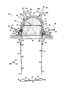
1 5 Figure I is a schematic representation of the principal components
and features
of an exercise device in keeping with the present invention, and intended for
use in the
performance of resistance and/or aerobic exercises;
Figure 2 is a schematic representation of the principal components, where an
additional pair of components has been added;
Figure 3 is a schematic representation similar to that of Figure 2, where yet
an
additional component has been added;
Figure 4 is a schematic representation indicating how the length of the first
elastic member in keeping with the present invention may be shortened to some
extent;
Figure 5 is a schematic representation similar to that of Figure 4, indicating
how
the length of the first elastic member may be shortened to a greater extent
than as
illustrated in Figure 4;
Figure 6 is another schematic representation indicating how another short
elastic
member, optionally having higher tensile strength, may be attached to the
first elastic
member so as to thereby increase the tensile strength of the first elastic
member; and
-10-
CA 02658198 2009-03-12
Figure 7 is a further schematic representation indicating how the tension
applied
by the first elastic member can be overcome by additional, optional elastic
members
attached to a user's hand.
DETAILED DESCRIPTION OF THE PREFERRED EMBODIMENTS:
The novel features which are believed to be characteristic of the present
invention, as to its structure, organization, use and method of operation,
together with
further objectives and advantages thereof, will be better understood from the
following
discussion.
Turning first to Figure 1, a schematic representation of an exercise device in
keeping with present invention is shown at 10. It will be understood that the
device as it
is illustrated in Figure 1 is as seen from the back of the user.
The principal components of the exercise device which is shown are a vest 12
which is adapted to encircle at least the upper chest and back region of the
body of the
user. There is a first elastic member 14, at the ends of which are clips 13,
for attaching
to foot straps 16. Foot straps 16 are typically adjustable length straps which
are
primarily intended to be fitted around each foot of the user. Clips 13 are any
suitable
fasteners adapted to be fitted to foot straps 16, and preferably, are adapted
to be
connected to a simple metal or plastic ring 32, as discussed hereinbelow,
attached to foot
straps 16.
It will be understood, of course, that the first elastic member 14 has a
predetermined length when at rest -- that is, when it has not been placed in
tension. That
predetermined length will ordinarily be such that, when the first elastic
member is
intended for use on the legs of the user, the clips 13, found at the ends of
first elastic
member 14, will be found generally in the position of the knees of the user.
It will be
further understood, of course, that the predetermined length and size of the
first elastic
member 14 may be different from one exercise device 10 to another, whereby
various
manufactured exercise devices may be worn by any member of my family, for
example,
such as by children, teenagers, and adult men and women having various
physical
appearances insofar as their girth and height may be concerned. In any event,
it will be
-11-
CA 02658198 2009-03-12
understood that when the foot straps 16 are attached to clips 13, and foot
straps 16, are
place on the feet of user, there will be a first initial tensile force which
develops in the
elastic member, and against the resistance of which aerobic exercises will be
performed.
A pair of vest straps 18 are provided, and they are intended to go over the
shoulders of the user, and connect to a belt 28 by connecting adjustable strap
ends 17A
to 17B, and 17C to 17D, in any known manner.
A back panel 20 is provided so as to extend across at least the upper back
region
of the user, especially between the shoulder blades. The major central region
of the
back panel 20 is typically made of a mesh material for purposes of maintaining
the body
of the user cooler than it might otherwise be.
An optional pack or pocket 19 can be provided on the back of panel 20 for
storage of the various elastic tubing components, when any of these are not in
use. Other
pockets can be provided as desired for storage of any other devices, such as
CD players,
radios, iPods, or the like.
A principal feature of the present invention is the provision of an enclosed
pathway 24, shown as a clear pathway for illustrative purposes, which is
affixed to the
vest 12 in the back region thereof, and which provides a pathway or "tunnel"
through
which the first elastic member 14 is passed. Thus, it can be seen that whether
or not the
first elastic member is in tension or is not in tension, its placement with
respect to the
back and shoulders of the user will be substantially in a fixed position. It
will also be
appreciated that the configuration of the enclosed pathway 24 is substantially
in an
inverted "U" so that the legs 23 and 25 of the pathways 24 thereof extend
downwardly
with respect to an apex 27.
It will be appreciated that exercises such as leg extensions or squats may be
performed when the foot straps 16 are associated with the feet of the user so
that the first
elastic member is in tension prior to any exercise being performed.
So as to assist the placement of the vest 12 in a body encircling manner, the
vest
is also provided with a weblike belt or girdle 28 which extends around the
body on the
user and fastens at the front thereof in any known manner, such as with Velcro
fasteners.
Typically, the length from top to bottom of the vest 12 -- that is, from the
uppermost
-12-
CA 02658198 2009-03-12
region of the back panel 22 to the lower edge of the belt 28 -- is such that
the belt 28
will encircle the body of the user in the region between the armpits and
waist, and
usually more or less at or near the bottom of the rib cage or the area just
below the chest.
A pair of second elastic members 34 are optionally attached to the first
elastic
member 14 at or near the openings of pathway 24. A hand grasping element 38 is
provided at the end or each of second elastic members 34. A clip 15 such as a
fastener,
is included as part of hand grasping element 38. Clip 15 may be the same as,
or different
from, clip 13.
It will be understood, however, that second elastic member 34 may be attached
directly to vest 12, or optionally to a ring 32, on first elastic member 14,
both as shown
in Figure 1.
A further significant feature of the construction of the exercise device in
keeping
with the present invention is the provision of optional guide means 30 which
are affixed
to the vest 12 in the area of the opening of the ends of pathway 24, and
through which
first elastic member 14 or second elastic members 34 can also pass when they
are
connected to first elastic member 14 or to vest 12. The guide means 30 may be
a loop of
material through which the first 14 and/or second elastic member 34 may pass
in a
reasonably frictionless manner, or guide means 30 may be a pulley, or the
like.
However, it should be noted that the spacing between the two guide means 30 is
preferably at least 50% of the width of the user's back, and more preferably
is the width
of the back, apart, in the region where belt 28 is placed. The spacing is
preferably such
that, in general, the guide members 30 are located near the sides of the user.
A third elastic member 40 is provided which is connected at one end to belt
28,
and at an opposite end to first elastic member 14. Third elastic member 40 is
connected
to belt 28 at a point which will be located towards the front of the user, and
thus, in front
of the pathway 24 openings, or guide means 30. In use, this third elastic
member 40
tends to pull the first elastic member 14 forward as it exits pathway 24, and
provides a
more vertically balanced feeling to the user.
A fourth elastic member 42 is fitted (either permanently or releasably) to
foot
straps 16 so that tension can be applied between the feet of the user, as and
when desired
-13-
CA 02658198 2009-03-12
in the performance of various exercises.
Referring still to Figure 1, one additional feature of the present invention
will be
noted. That is, there are a plurality of rings 32 which are secured to the
first elastic
member 14 along the length of each leg of its "U" configuration, in regions
which are
not in the enclosed pathway 24. Indeed, the rings 32 are found on the first
elastic
member in the regions of each leg thereof which are below belt 28 and/or guide
means
30. Rings 32 are preferably circular or D-shaped plastic or metal rings, that
are attached
to first elastic element. Rings 32 are adapted to receive a fastener clip,
such as shown as
the clip 15, and using clip 15, one ring 32 can be connected to another ring
32, in the
manner described hereinbelow.
Rings 32 may also be attached together using an optional hand grip 38A, shown
having a clip 15A, (in combination with further ring 32) which can be attached
to any
one ring 32, or to a combination of rings 32.
However, it must be noted that rings 32 are such that a clip 15 or any pair of
clips 15 on either one of the legs of the first elastic member 14 may be
affixed or
connected to any other ring 32 on the same leg, so as to thereby effectively
shorten the
at rest length of the elastic member. Accordingly, if the exercise device is
used by a
user for whom the predetermined length of the first elastic member is correct
(adult,
teenager, child, etc.), then the effectively shortened first elastic member
will be in
greater tension, and the initial tensile force in the elastic member will have
increased
over that of a first elastic member when in its original placement. This is
described later
in association with Figures 4 and 5.
Rings 32 are also found on second elastic member 34, and can be used to
shorten
the length of member 34. Further, rings 32 are also found on fourth elastic
member 42 to
adjust the length of member 42.
Optionally, adjustable straps can be provided to ensure a snug fit of vest 12
on
each user, by attaching optional adjustable straps 21A to 21B, or 39A to 39B,
and/or
29A to 29B. Further, optional protective tabs 41 can be provided on vest 12,
which
prevent any elastic tubes from rubbing directly against the user.
Referring now to Figure 2, a modification of the exercise device which has so
far
-14-
CA 02658198 2009-03-12
been described is shown in schematic manner. Here, it is seen that the foot
straps 16A
are permanently affixed to the end of first elastic member 14. It can be seen
that second
elastic members 34 are affixed to first elastic member 14 in the area
immediately
adjacent to guide means 30.
Each of the second elastic members 34 has a hand grasping member 38 secured
to its outer end. The length of each of the elastic members 34 will be such
that in their
un-stretched, at-rest, form, the hand grasping members 38 will be found in a
position
somewhere between the wrists and the shoulders of the user. It will now be
seen that the
second elastic members 34 and their grasping members 38 may be employed in the
performance of exercises that are primarily intended for the upper torso of
the user,
including the chest, shoulders, arms, hands, and wrists of the user. These can
include,
for example, shoulder or chest presses, or the like. To that end, the grasping
members 38
may be designed so as to be grasped by the hand, to fit around the wrist, or
both.
Typically, exercises using grasping member 38 are performed primarily against
the resistance in second elastic member 34 as a consequence of its own elastic
memory
and the initial tensile strength thereof. However, because second elastic
member 34 is
attached to first elastic member 14, some of the total tension encountered
during arm
exercises also results from the tensile resistance of member 14.
Another option, however, is for second elastic member 34 to be connected
directly to vest 12 so that virtually all of the tension is provided by second
elastic
member 34, as previously described.
Figure 3 is essentially the same as Figure 2, except for the addition of
fourth
elastic member 42. That member 42 is permanently secured at one end to foot
strap 16
which is associated with one foot of the user. The other end of member 42 can
be
releasably attached to the other foot strap 16 on the other foot of the user.
When
attached to both feet, additional exercises can be performed under tension.
These include
exercises such as hip abductions, single leg lifts to the front, side or back,
and so on.
When fourth elastic member is not needed, it can be un-connected from one foot
strap
16, and wrapped around the other foot of the user.
The length of fourth elastic member 42 can be adjusted using clips 32 so that
the
-15-
CA 02658198 2009-03-12
tension applied can be adjusted, and thus modify the type and nature of the
exercise.
Referring now to Figures 4 and 5, these figures illustrate the manner in which
the
effective length of the first elastic member 14 can be shortened. In Figure 4,
two
adjacent rings 32 are connected one to the other so that a loop 42 is formed
between
them. This will result in the length of the first elastic member 14 being
shorter than its
original length, becoming length LI. It will be understood that the material
of the first
elastic member which comprises the loop 42 will not be in tension, and that
the tension
forces which are created in the first elastic member are transferred between
the two rings
32 which have been affixed one to the other. The clip which joins rings 32
together is
not shown, but this can be provided with a separate clip or a clip 15A
included as part of
optional hand grasping element 38A.
Figure 5 shows a situation where a pair of rings 32 which have other rings 32
that are intermediate of the selected pair of rings, are attached one of the
other. In the
example shown, there are two rings 32 which are attached one to the other, and
there are
three intervening rings 32 which are now found on the slack loop 44. as
before, the
length of the first elastic member 14 in the example of Figure 5 will be
shorter still,
being in this case length L2. It will also be clear to one skilled in the art
that the tension
forces in the first elastic member 14 in the example of Figure 5 will be
higher than the
tension forces in the first elastic member 14 as shown in Figure 4, for the
same user or a
user of the same size.
Turning to Figure 6, a further option by which the tension forces in the first
elastic member 14 may be increased is shown. Here, T1 represents the original
tension
in the first elastic member 14, and T2 represents the tensile strength of an
additional,
preferably stronger elastic member 46. When the first elastic member 14 is put
into
tension, the tensile strength T, will be imparted through the entire length of
the first
elastic member 14, so that an increased tension will be encountered when first
elastic
member is put into tension in the area of member 46.
Finally, in Figure 7, a further option is shown wherein an optional hand
grasping
element 38A, with (or without) a further elastic member 34A, is attached to a
ring 32 on
first elastic member 14. If the tension of elastic member 14 is too great for
a particular
-16-
CA 02658198 2015-08-28
user for a selected exercise, then element 38A (with optional elastic element
34A) can
be attached to ring 32 so that the user can also use their hands and arms to
assist in
overcoming the tension of first elastic member 14.
Other modifications and alterations may be used in the design and manufacture
of the apparatus of the present invention.
Throughout this specification and the claims which follow, unless the context
requires otherwise, the word "comprise", and variations such as "comprises" or
"comprising", will be understood to imply the inclusion of a stated integer or
step or
group of integers or steps but not to the exclusion of any other integer or
step or group
of integers or steps. Further, the invention illustratively disclosed herein
suitably may be
practiced in the absence of any element which is not specifically disclosed
herein.
Moreover, the word "substantially" when used with an adjective or adverb is
intended to enhance the scope of the particular characteristic; e.g.,
"substantially in a
fixed position" is intended to mean, in this particular example, that there
shall be no
significant relative movement of the back panel 20 with respect to the back of
the user,
or vice versa.
-17-