Note: Descriptions are shown in the official language in which they were submitted.
CA 02658670 2009-03-20
PAINT TRAY HOLDER FOR SIDE MOUNT ON LADDER
FIELD OF THE INVENTION
This invention relates to a paint tray holder of the type for holding
paint during painting with a brush or paint roller and is particularly
designed to
be mounted on a side of a ladder.
BACKGROUND OF THE INVENTION
Often when painting internal or external walls or when painting
ceilings the area to be painted is higher than an individual can reach. This
usually requires the use of a ladder to enable the painter to reach the area
to
be painted. This creates a problem for the painter in that it requires that a
brush or roller and a paint supply be utilized while standing on the ladder.
Working on a ladder in this manner with a brush or roller while trying to
manage a paint supply can be difficult and potentially dangerous. To help
solve this problem a holding device may be used to hold the paint supply
allowing the painter to have a free hand white painting. A variety of devices
have been employed in this manner most of which have various drawbacks.
Hook arrangements for suspending paint cans from the rungs of a
ladder have been utilized. When in use these hooks are placed on the rungs of
the ladder and can get in the way of the painter when moving up and down the
ladder and are not usable with paint rollers. Paint trays are also a common
means of containing a paint supply. Although these trays are usable with both
brushes and rollers they are also usually held on the rungs of a ladder
thereby
presenting the same problems when moving on the ladder.
CA 02658670 2009-03-20
2
Other prior art solutions include paint tray holders that engage
over rungs of a ladder or clamp to the one of the legs or rails between which
the ladder's rungs or steps extend to support the paint tray laterally outward
from the ladder so as to avoid or minimize blocking of the rungs. However,
drawbacks of prior art such arrangements include bulky constructions, complex
installation on or repositioning along the ladder and inadequate support or
balancing of paint-filled trays.
SUMMARY OF THE INVENTION
According to a first aspect of the invention there is provided a paint
tray holder for mounting a paint tray on the leg of a ladder having a
plurality of
rungs, said paint tray having four side walls and a bottom wall said paint
tray
holder comprising:
a mounting plate arranged substantially parallel to a side wall of the
paint tray engaging said side wall;
an attachment means for attaching the side wall of the paint tray to
the mounting plate;
a support arm connected to the mounting plate at a position below
the attachment means and extending outwardly away from the mounting plate to
one side thereof to a location beneath the paint tray at a distance from the
mounting plate;
a tray carrying member supported on the arm member at the
position beneath the paint tray and extending in a direction transverse to the
arm
CA 02658670 2009-03-20
3
member at the distance to the mounting plate to engage the bottom wall of the
paint tray at multiple positions therealong; and
a clamp connected to the mounting plate on a side of the mounting
plate opposite the tray support member, said clamp being arranged to support
the
paint tray on the leg of the ladder and being arranged such that the paint
tray lies
to one side of the ladder and clear of the rungs of the ladder.
The tray carrying member of the paint tray holder provides improved
support over prior art clamping arrangements that engage the side wall of the
tray
but only provide bottom support thereof at a single point or location along
the
length of the tray while using less material for this bottom support than
prior art
arrangements using large-area plates disposed beneath the tray over the full
length and width thereof for the tray to sit flat atop such a plate.
Preferably the support arm is movably connected to the mounting plate
for selective raising and lowering of the tray carrying member relative to the
mounting plate to vary a lateral angle at which the paint tray sits relative
to the
mounting plate in a direction transverse thereto.
The paint tray holder may comprise a support projection carried on the
mounting plate and projecting therefrom to the side thereof on which the
support arm
extends away from the mounting plate, the support arm being pivotally
connected to
the support projection at a pivot point spaced from the mounting plate along
the
support projection for pivoting about a pivot axis transverse to a length of
the support
arm and the paint tray further comprising a hook member having an externally
threaded stem and a curved hook end, wherein the threaded stem of the hook
CA 02658670 2009-03-20
4
member passes perpendicularly through a ledge portion of the projection that
is
parallel to the pivot axis and the curved hook end curves through an end
portion of
the support arm that extends parallel to the pivot axis in the direction
transverse to
the length of the support arm at an end of the support arm opposite the tray
carrying
member, an internally threaded member being cooperatively engaged with the
threaded stem of the hook member against a side of the ledge portion of the
projection opposite the hook end of the hook member for selective rotation of
the
internally threaded member to selectively displace the threaded stem through
the
ledge portion to lift or lower the end portion of the support arm to pivot the
support
arm about the pivot axis in a respective direction to lower or raise the tray
carrying
member.
In this instance, preferably a coil spring is disposed about the threaded
stem of the hook member between the ledge portion of the support projection
and a
stop collar defined on the hook member on a side of the ledge portion opposite
the
internally threaded member, and the threaded stem of the hook member
preferably
projects upward through the ledge portion of the support projection.
Preferably the tray carrying member has an upper boundary that is
shaped to engage the bottom wall of the paint tray at differently sloped
sections
thereof.
Preferably the tray carrying member has an upper boundary that dips
downward moving therealong to accommodate a reservoir of the paint tray and
engage the bottom wall of paint tray both at the reservoir and elsewhere along
the
paint tray.
CA 02658670 2009-03-20
Preferably the tray carrying member comprises a plate, an upper edge
of which defines the upper boundary of the tray carrying member.
Preferably a portion of the tray carrying member arranged to receive
the reservoir of the paint tray is positioned proximate the clamp in a
direction along
5 which the mounting plate extends.
The tray carrying member may be releasably connected to the support
arm to facilitate selective installation of differently shaped tray carrying
members
arranged to accommodate seating of differently shaped paint trays thereatop.
Preferably the clamp comprises a first clamping member and a second
clamping member movable toward and away from the first clamping member to
clamp the leg of the ladder against the first clamping member.
The second clamping member may be carried on a clamp arm that is
pivotally mounted on a mounting arm carried on the mounting plate to project
away
therefrom on a side thereof opposite the paint carrying member, with the clamp
arm
being lockable in a clamping position relative to the first clamping member.
Preferably the clamp arm is self locking upon pivoting into the clamping
position, the
clamp arm preferably comprising a projection sized for receipt in a respective
hole
provided in the mounting arm at a position to align with the projection with
the clamp
arm in the clamping position, the clamp arm being spring biased toward the
mounting arm to automatically force the projection into the hole upon pivoting
of the
clamp arm into the clamping position. Preferably the second clamping member is
movable relative to the clamp arm to tighten or loosen clamping of the ladder
leg
with the clamp arm in the clamping position.
CA 02658670 2009-03-20
6
The paint tray holder may be provided in combination with the paint
tray, the paint tray comprising a reservoir at one end from which the bottom
wall of
the paint tray slopes upward and a standing support feature at an opposite end
to
support the opposite end when the paint tray is seated on a flat surface, the
paint
tray being installable on the paint tray holder or usable separate therefrom.
The tray carrying member, with the paint tray carried thereon, is
preferably situated entirely to a same side of the opposite end of the paint
tray as the
reservoir end thereof, and preferably to a same side of the standing support
feature
as the reservoir end.
The standing support feature may comprise a pair of legs spaced apart
along the opposite end of the paint tray, the tray carrying member of the
paint tray
holder being situated between the pair of legs along a width of the tray
defined by
said opposed end.
Components of the attachment means are preferably preinstalled on
opposing ones of the paint tray and the paint tray to require no modification
of the
paint tray by an end-user.
According to a second aspect of the invention there is provided a paint
tray holder for mounting a paint tray on the leg of a ladder having a
plurality of
rungs, said paint tray holder comprising:
a clamp comprising a stationary clamping member for placement
against an outer lateral face of the leg of the ladder and a movable clamping
member movably connected to the stationary clamping member for selective
movement toward and away therefrom to engage with and disengage from an
CA 02658670 2009-03-20
7
inner lateral face of the leg of the ladder opposite the outer lateral face
for
clamping and releasing of the leg of the ladder between the stationary and
movable clamping members; and
a paint tray support connected to the clamp to project away from the
stationary clamping member on a side thereof opposite the movable clamping
member to support the paint tray on the leg of the ladder to one side thereof
clear
of the rungs when the clamp is engaged to the ladder leg;
wherein a connection between the movable clamping member and
the stationary clamping member comprises a pivotal connection about which the
movable clamping member is pivotable to swing the movable clamp member
away from the stationary clamping member and out from between adjacent rungs
of the ladder to allow sliding of the paint tray holder along the leg of the
ladder for
re-clamping at a different position therealong.
Prior art paint tray holders that either engage one or more rungs or
engage the ladder leg between select rungs require full and complete
disengagement of the entire holder from the ladder in order to reposition the
holder to a new height or position along the ladder. During such removal of
the
device, removal of the tray or very careful and cautious handling of the
holder is
required to avoid spilling of paint from the tray. A paint holder of the
present
invention having the above mentioned swing-away clamp holder allows the holder
to be simply slid along the ladder while remaining pressed thereagainst to
maintain the orientation of the paint try relative to the ladder leg.
CA 02658670 2009-03-20
8
Preferably the pivotal connection comprises a pivoting clamp arm on
which the movable clamping member is supported, the clamp arm being lockable
in a fixed position relative to the stationary clamping member and the movable
clamping member being movable relative to the clamp arm to move toward and
away from the stationary clamping member with the clamp arm locked in the
fixed
position.
Preferably the pivotal connection is self locking upon pivoting of the
clamp arm into the fixed position.
Preferably the clamp arm is spring biased to automatically lock itself in
the fixed position.
Preferably the pivotal connection pivotally carries the clamp arm on a
mounting arm connected to the stationary clamping member and the clamp arm
comprises a projection sized for receipt in a respective hole that is provided
in a
mounting arm and positioned to align with the projection with the clamp arm in
the
fixed position, the clamp arm being spring biased toward the mounting arm to
automatically force the projection into the hole upon pivoting of the clamp
arm into
the fixed position.
BRIEF DESCRIPTION OF THE DRAWINGS
In the accompanying drawings, which illustrate an exemplary
embodiment of the present invention:
Figure 1 is an elevational view of a reservoir end of a paint tray carried
by a paint tray holder installed on the right side of a ladder.
CA 02658670 2009-03-20
9
Figure 2 is an elevational view of the paint tray and paint tray holder of
Figure 1 from an opposite end of the paint tray.
Figure 3 is an elevational view of the paint tray and paint tray holder as
removed from the ladder and viewed from a side of the paint tray.
Figure 4 is an elevational view of the paint tray and paint tray holder of
Figure 3 from an opposite side of the paint tray.
Figure 5 is an elevational view of the paint tray and paint tray holder of
Figure 3 after adjustment of a longitudinal leveling means of the paint tray
holder to
change a relative angle between the paint tray and a clamping mechanism of the
paint tray holder.
Figure 6 is an elevational view of the paint tray holder of Figure 1 with
the paint tray removed.
Figure 7 a bottom plan view of the paint tray holder of Figure 6.
Figure 8 is an elevational view of the paint tray holder of Figure 2 with
the paint tray removed.
Figure 9 is an overhead plan view of the paint tray holder of Figure 8
showing a withdrawn position of a movable clamping member in broken lines.
DETAILED DESCRIPTION
Referring to Figures 1 to 9 the paint tray holder is shown generally at
10. The paint tray holder 10 comprises a clamping assembly 12 for mounting a
tray 14 on a ladder 16. The clamping assembly 12 comprises a clamp 18, a
longitudinal leveling means 20, and a lateral leveling means 22. The clamping
CA 02658670 2009-03-20
assembly 12 is fixed to the paint tray 14 and is secured to a leg 17 of the
ladder
16 by the clamp 18.
The tray 14 is of the type for holding paint when painting with a
brush or paint roller. The tray 14 has a bottom 20 and four walls, a front
wall 21,
5 back wall 24, and side walls 26 and 28. The distance from the top edge 30 of
the
back wall 24 to the bottom edge 32 of the back wall 24 is smaller than the
distance form the top edge 34 of the front wall 21 to the bottom edge 36 of
the
front wall 21. The bottom 20 slopes downwards in a direction from back to
front
to a point 38 spaced back from the bottom edge 36 of the front wall, thereby
10 forming a paint application surface 40. The bottom 20 then projects forward
horizontally to the bottom edge 36 of the front wall forming a reservoir 42 at
the
front end of the tray.
The sloping portion of the bottom wall 20 of the tray 14 of the
illustrated embodiment is structured as two distinctly sloped portions 20a and
20b, the first sloped portion 20a sloping linearly and obliquely downward from
the bottom edge 32 of the back wall 24 at a first angle a majority of the
distance
to the reservoir 42 and second sloped portion 20b sloping linearly and
obliquely
downward from the first sloped portion 20a to the horizontal reservoir bottom
20c
at over a shorter distance, and at a steeper angle, than the first sloped
portion
20a. The steeper sloped section 20b defines a side of the reservoir opposite
the
front wall 21 to provide a distinct identifiable division between the
reservoir 42
and the paint application or rolling surface 40. As is known in the art, this
CA 02658670 2009-03-20
11
surface 40 may be provided with a series of transverse ridges projecting
upward
at spaced locations therealong.
The tray includes an outwardly projecting flange or lip 41 projecting a
short distance outward from the perimeter of the tray's open top along the top
edges of the front, back and side walls. The tray also 14 includes a mounting
pin
46 arranged on a respective side wall 28 to receive the clamping assembly 12
when the paint tray holder 10 is mounted on the side of the ladder 16. The
mounting pin 46 has a first end 48 situated inside the tray 14 and extends
laterally outwards from the tray through a hole in the side wall 28 below the
upper edge thereof to a second end 50. The first end features a head or plate
48a fixed thereto inside the tray 14 and sized to prevent withdrawal of the
first
end 48 from the tray through the hole in the side wall 28. A retaining means
52 is arranged at the second end 50 for retaining the clamping assembly 12
on the tray 14. One example of an appropriate retaining means 52 is a
fastener such as a wing nut where the mounting pin 46 has a threaded shaft,
for example as defined by a screw or bolt used as the pin.
The clamp assembly 12 includes a mounting plate 54 parallel to
the side wall 28 of the paint tray 14 for engaging therewith. The mounting
plate 54 has a front face 56 facing the paint tray 14, a rear face 58 facing
away from the paint tray 14, a top edge 60, a bottom edge 62, and side edges
64 and 66 facing opposite ends of the paint tray 14. The mounting plate 54
includes a notch 68 in the top edge 60. The notch 68 has a mouth 70 and an
end 72 and extends into the mounting plate 54 vertically downward from the
CA 02658670 2009-03-20
12
mouth 70 to the end 72 at the top edge 60 of the mounting plate 54. The
notch 68 receives a portion of the mounting pin's shaft between the paint tray
side wall 28 and the retaining means 52 by lowering of the paint tray
adjacently along the front face 56 of the mounting plate 54 from above and
helps hold the tray 14 laterally on the clamping assembly 12 reducing the risk
of the tray 14 tipping laterally of the clamping assembly 12.
The mounting plate 54 includes a slot 74 adjacent the side edge
66. The slot 74 extends through the mounting plate 54 from the front face 56
to the rear face 58 and across a substantial portion of the plate's vertical
width to slot ends 76 and 78 adjacent the top and bottom edges 60 and 62 of
the mounting plate 54. The slot 74 curves in a direction towards the opposite
side edge 64 as it extends to its ends 76 and 78.
The clamp 18 is mounted on the mounting plate 54 by the
longitudinal leveling means 20. The longitudinal leveling means 20 comprise
an L shaped plate 80 arranged parallel to the mounting plate 54 on the rear
side thereof. The leg 82 of the L plate 80 extends from a first end 84
adjacent
the side 66 of the mounting plate 54 along the bottom edge 62 of the
mounting plate 54 in a direction towards the side 64 of the mounting plate 54.
The foot 88 extends from adjacent the bottom edge 62 upwards to a second
end 85 spaced downward from the top edge 60 of the mounting plate 54. The
leg 82 of the L plate 80 has a hole 86 through the first end 84 arranged to
lie
over the slot 74 in the mounting plate 54. A second hole 90 extends through
the foot 88 adjacent the second end 85 of the L plate 80. The second hole 90
CA 02658670 2009-03-20
13
is arranged to align with a hole 92 in the mounting plate 54 lying nearer side
edge 64 of the mounting plate 54 than opposite side edge 66.
The mounting plate 54 is pivotally connected to the L plate face-
to-face therewith by a pin 94 extending through the aligned holes 90 and 92.
The arcuate shape of the slot 74 in the mounting plate 54 is centered on the
axis of this pin 94. The pivot connection allows the mounting plate 54 to
slide
relative to the L plate 80. Pivotal movement of the plates 54 and 80 is
restrained by a or removable and reengageable fastener 95 arranged through
the slot 74 and the first hole 86. The removable and reengageable fastener 95
when tightened prevents movement of the mounting plate 54 relative to the L
plate 80 and allows sliding movement of the mounting plate relative to the L
plate 80 when loosened by clamping and releasing the plates into and out of
frictional engagement with one another respectively. One example of an
appropriate removable and reengageable fastener is a bolt and wing nut.
Referring to Figure 9, the clamp 18 is fixed to the longitudinal
leveling means 20 and comprises a clamping mechanism 100 and a stationary
clamping member 102. The clamping mechanism 100 includes a side plate
98 of the clamp 18 has a top edge 104, a bottom edge 106, and side edges
108 and 110. The side plate 98 is fixed to the L plate 80 along one of its
side
edges 108 and is arranged perpendicular to the L plate 80 extending
rearwards therefrom.
The clamp 18 has a closed side 114 provided the side plate 98.
The closed side 114 helps to align the leg 17 of the ladder 16 within the
clamp
CA 02658670 2009-03-20
14
18. The clamp 18 also has an open side 116 opposite the closed side 114 to
receive the leg 17 therethrough. The direction running from the open side to
the closed side is the direction of insertion into the clamp 18. When the
paint
tray holder 10 is mounted on a ladder the direction of insertion runs
perpendicular to a line running longitudinally through the rungs of the
ladder.
The direction running perpendicular to the direction of insertion is the
direction
of clamping action.
The clamping mechanism 100 also includes a support plate 118
fixed to the L plate 80 at a first end 120 and fixed along one side 122 to the
side plate 98 on a face of the side plate 98 facing the side edge 66 of the
mounting plate 54. The support plate 118 extends past the end of the side
plate 98 to a free end 124. A pivot hole 126 extends through the support plate
118 adjacent the free second end 124 thereof. An additional through hole 128
is provided in the support plate 118 to one side of the pivot hole 126 at an
aligned position therealong adjacent the free second end 124.
A clamp arm 130 comprises an elongate member having a first
end 132 and a second end 134, and is connected to the support plate 118 at
its first end 132. The clamp arm 130 is connected to the support plate 118 for
pivotal movement about the axis of the pivot hole 126. A bolt 136 extends
from a first end 138 through a hole 140 in the clamp arm 130 and through the
pivot hole 126 in the support plate 118 to a second end 142. A coil spring 144
is arranged around the bolt 136 between the support plate 118 and a nut 145
fitted on the bolt 136 proximate the second end 142 thereof. The coil spring
CA 02658670 2009-03-20
144 biases the clamp arm 130 towards the support plate 118. A projection 146
is fixed to the clamp arm 130 and is arranged to engage within the hole 128 in
the support plate 118 securing the clamp arm at a fixed position relative to
the
fixed-together support plate 118 and L-plate 80.
5 Applying a force to the clamping arm 130 in a direction away from
the support plate 118 frees the projection 146 from the hole 128 and allows
the clamping arm 130 to pivot about the hole 126 in the support plate 118.
Removing the force from the clamping arm 130 when the clamping arm 130 is
repositioned back over the hole 128 causes the clamping arm 130 to be
10 biased back towards the support member 118 and reengages the projection
146 within the hole 128 to once again secure the clamping arm 130 in place.
A mounting member 166 is located at the second end 134 of the
clamping arm 130. The mounting member 166 includes a threaded hole 168
extending therethrough perpendicular to the length of the support plate 118
15 measured between the opposing ends 132, 134 thereof. A movable clamping
member 170 is arranged through the hole 168. The stationary clamping
member 171 comprises a hollow rectangular tube fixed to the L plate 80 such
that it aligns with the threaded hole 168 in the mounting member 166 when
the clamp arm 130 is in its locked position engaging the projection 146 in the
hole of the support arm 118.
The movable clamping member 170 comprises a threaded
elongate member 172 which is round in cross section and extends through the
threaded hole 168 in the mounting member 166 to an end 174 lying between
CA 02658670 2009-03-20
16
the clamping arm 130 and the stationary clamping member 171 with the clamp
arm 130 in the fixed position. The threaded elongate member 172 has a flat
plate 176 arranged at said end 174, and a handle 178 arranged at an end 180
opposite for rotating the elongate member 172. With the clamp arm 130 in the
fixed position, rotating the elongate member 172 in a first direction causes
the
flat plate 176 to be linearly displaced towards the stationary clamping member
171 and rotating the elongate member in a second direction causes the flat
plate 176 to be linearly displaced away from the stationary clamping member
171.
With the clamping arm automatically locked in a fixed clamping
position relative to the stationary clamping member 171 by the biasing of the
clamping arm's projection into the respectively sized and positioned hole in
the
support plate 118, the threaded elongate member 172 is movable toward and away
from the fixed clamping member 171 to clamp the leg of the ladder
thereagainst. To
install the paint tray holder on a ladder, the threaded elongate member is
rotated in a
loosening direction to pull the clamping plate 176 back to mounting member
166, or
sufficiently theretoward to accommodate the ladder leg between the clamping
plate
176 and the fixed clamping member 171. If additional room is needed to
accommodate the cross-sectional shape of the ladder leg, for example to insert
a
portion thereof into the space left between the fixed clamping member 171 and
the
side plate 98, then the clamp arm 130 can be raised to release the projection
from
the hole in the support plate 118 and unlock the clamp arm, which is then
pivoted to
move away from the fixed clamping member 171. Once the ladder leg is in place
CA 02658670 2009-03-20
17
with the stationary clamping member 171 placed face-to-face against the outer
lateral face or side of the ladder leg, the clamp arm 130 is moved back into
its self
locking clamping position and the threaded member 172 is then tightened to
press
the clamping plate 176 against the inner lateral face or side of the ladder
leg to hold
the paint tray holder in place.
Should it later be desirable to move the holder along the ladder, for
example to move further up the ladder leg for painting of more elevated areas,
unlocking and pivoting of the clamp arm 130 away from the ladder leg provides
a
quick-release function freeing the clamping of the ladder leg and swinging the
clamp
arm 130, mounting member 166 threaded elongate member 172 and clamping plate
176 out from between adjacent rungs on the ladder. Through manual support of
the
holder, for example by gripping the stationary clamping member 171 to keep it
pressed along the outer face of the ladder leg, the ladder leg is maintained
against
the side plate 98 and fixed clamping member 171 and manually slid up along the
ladder leg to a new desirable position, at which point manual pivoting of the
clamp
arm 130 back to into its locked condition to once again engage the clamping
plate
176 against the ladder leg to secure the holder in its new position further up
the
ladder with only minimal, if any, rotation of the elongate threaded member 172
being
required through this repositioning process.
Figure 9 shows, in broken lines, the clamp arm 130 pivoted one
hundred and eighty degrees from the fixed clamping position perpendicular to
the
support plate 118 so that the clamp arm 130 and all components carried thereon
do
not extend past the side plate 98 to the side thereof on which the stationary
CA 02658670 2009-03-20
18
clamping member 171 is disposed. This thus completely withdraws all the moving
clamping components from between rungs of the ladder when the clamp arm 130 is
pivoted to the broken line position of Figure 9 from its previous clamping
position on
the ladder (Figures 1 and 2). In other embodiments, the pivot angle to which
the
clamp arm 130 is swung to complete the withdrawal of the movable clamping
member from between the ladder rungs and legs need not necessarily be one
hundred and eighty degrees. Also, it will be appreciated that same locking
function
used to secure the swing arm 130 in the fixed position can similarly be used
to
maintain the swing arm 130 in the withdrawn position during sliding
repositioning or
initial installation on the ladder by providing a second through hole at an
equal radial
distance from, but different angular position around, the pivot hole 126 as
the
illustrated through hole 128 in order to align with the clamp plate projection
146 with
the clamp arm 130 in the withdrawn position and receive the projection 146
under
the bias of the coil spring 144. In the illustrated embodiment where the fixed
and
withdrawn positions of the clamp arm 130 are one hundred and eighty degrees
apart, the second hole would be diametrically opposite the illustrated hole
128
across the pivot hole 126.
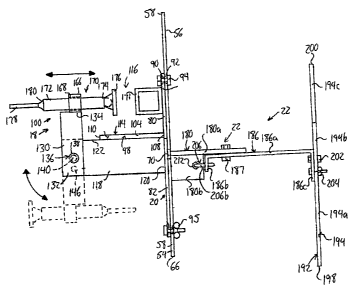
The lateral leveling means 22 are fixed to the front side of the
mounting plate 54 and projects under the tray 14 to support the tray 14 from
below and allow the tray 14 to be angled laterally, thereby adjusting the
lateral level of the tray 14. The lateral leveling means 22 comprise a
projecting support member 180 having a first end 182 and a free second end
184. The support member 180 is fixed to the mounting plate 54 at the first
CA 02658670 2009-03-20
19
end 182 and extends perpendicular to the mounting plate 54 and laterally
forwards therefrom to the second end 184. From its first end 182 to a point
part way between its opposite ends, the support projection 180 has an L-
shaped or right angle cross-section defining an upwardly extending wall
portion 180a parallel to the side edges 64, 66 of the rectangular mounting
plate 54 and a ledge portion 180b parallel to the top and bottom edges 60, 62
of the mounting plate. Only the upstanding wall portion 180a extends and
defines the full length of the projecting support member 180 between its
opposing ends 182, 184.
A support arm 186 has a pivotal connection 187 to the support
member 180 proximate the free end 184 on the upstanding wall portion 180a
past the end of the ledge portion 180b. The support arm 186 extends to
opposite ends 188, 190 on opposite sides of the pivotal connection 187,
extending forwardly away from the mounting plate 54, that is, to the side
thereof opposite the clamp 18, from its first end 188 nearest the mounting
plate 54 to its second end 190 thereopposite. The support arm 186 has a
squared off U-shape, having a central a plate-like central portion 186a
defining a longitudinal direction of the arm extending laterally away from the
mounting plate 54 in a plane normal thereto, and first and second end
portions 1861 , 186c projecting from a common face of the central portion 186
to a common side thereof in parallel planes normally transverse thereto. In
the illustrated embodiment, the arm is an integral piece having bent end
CA 02658670 2009-03-20
portions with top and bottom edges each spanning all three sections of the U-
shaped piece.
A tray carrying member 192 is provided by an elongate plate fixed
face-to-face against the second end portion 186c of the support arm 180 to
5 lie in a plane perpendicular to that of the support arm's central portion
186a
and project from both sides thereof. When the paint tray is lowered into
engagement with the mounting plate 54, that is to lower the pin 44 of the
paint tray into the slot-shaped notch 70 in the top of the mounting plate 54
and seat the optional flange, rim or lip 41 of the tray on the top edge 60 of
the
10 mounting plate, the tray carrying member 192, the bottom wall 20 sits atop
an
upper edge 194 of the tray carrying member 192 at a distance from the
mounting plate near the opposite side wall 26 of the paint tray 14.
A bottom edge 196 of the illustrated tray carrying plate 192 is
linear, with opposing end edges 198, 200 of the carrying plate 192 being
15 parallel to one another and perpendicular to the bottom edge 196. From the
first end 198 of the tray carrying plate nearest the side edge 66 of the
mounting plate 54 adjacent which the slot 74 is formed, the linear bottom
edge 196 of the carrying plate 192 slopes obliquely downward relative to the
bottom edge 62 of the rectangular mounting plate 54, this angle defining a
20 longitudinal direction or lengthwise dimension of the carrying plate 192
that
generally follows along the bottom wall of the paint tray at a distance
therebelow. The top edge 194 however is not linear from end to end, but is
instead shaped to cooperate with the shape of the paint tray's bottom wall 20
CA 02658670 2009-03-20
21
to engage thereagainst at different positions therealong. From the first end
198 of the tray carrying plate nearest the side edge 66 of the mounting plate
adjacent which the slot 74 is formed, a first portion 194a of the top edge 194
of the carrying plate extends parallel to the bottom edge 196. A second
portion 194b of the top edge 194 slopes obliquely downward relative to the
first portion 194a from proximate where the carrying plate 192 connects to
the support arm 186. A third portion 194c of the top edge 194 is obliquely
sloped relative to the second portion 194b from which it extends, and slopes
obliquely away from the bottom edge 196.
The second and third portions 194b, 194c of the top edge of the
carrying plate 192 meet below the bottom wall 20 of the paint tray 14 at or
proximate the point 38 at which the horizontal and steepest portions 20c, 20b
of the tray's bottom wall 20 meet. The third portion 194c of the carrying
member's top edge 194 contacts the tray's bottom wall 20 at the horizontal
portion 20c thereof defining the reservoir bottom and the first portion 194a
contacts the tray's bottom wall 20 at the first sloped section 20a extending
from the rear wall 24 of the tray opposite the reservoir 42. In the
illustrated
embodiment, the angles of the tray carrying plate are such that it contacts
the
paint tray 14 at only these two points, with the rest of the carrying's
plate's
upper edge 194 spaced below the tray, thereby leaving room to
accommodate variations in the shaping of different paint trays.
A bolt 202 passed perpendicularly through the parallel face-to-
face carrying plate 192 and support arm second end portion 186c provides a
CA 02658670 2009-03-20
22
pivot axis transverse to the carrying plate 192 for pivoting of the carrying
plate 192 relative to the support arm 186 on which it is carried. A
tightenable
and loosenable fastener 204, such as a bolt and wing-nut combination,
passes through overlapping holes the carrying plate 192 and the second end
portion 186c of the support arm parallel to the bolt 202, one of these holes
being a slot of arcuate shape curving about the axis of the bolt 202, or at
least being sufficiently large to accommodate arcuate motion of the fastener
about that axis. With the fastener loosened, the carrying plate 192 can thus
be pivoted to reorient its lengthwise dimension at a new angle relative to the
support arm 186. Alternatively, the carrying plate 192 and support arm 186
may instead be arranged to interconnect at a fixed non-adjustable angle.
The bolt 202, or equivalent pivot providing component, may also
use a bolt and wing-nut combination or other removable arrangement to allow
removal of the carrying plate 192 and thereby facilitate replacement of a
carrying plate 192 of one shape with any one of differently shaped carrying
plates each arranged for better. It will be appreciated that a single-fastener
arrangement may replace the use of separate pivoting and tightening
components and still facilitate one or both of a pivotal carrying plate and
removable carrying plate arrangement. Where the paint tray holder is
intended for use with a particular tray, the carrying plate 192 may be shaped
to contour the plate's upper edge to more closely conform to shape of that
particular type of tray.
CA 02658670 2009-03-20
23
The pivotal connection 187 of the support arm 186 to the support
projection 180 uses a bolt or other pivot pin structure passing
perpendicularly
through the upright wall portion 180a of the support projection 180 and the
central portion 186a of the support arm sitting parallel and adjacent thereto
to
provide a pivot axis perpendicularly transverse to the length-defining central
portion 186a of the support arm. An adjustment device operable to change
an angle at which the tray bottom 20 is oriented relative to the mounting
plate
54 in a vertical plane perpendicular to the mounting plate to facilitate
removal
of lateral tilt of the tray for leveling thereof uses a hook member 206
connected between the support projection 180 and the support arm 186 on
the same side of the pivotal connection 187 therebetween as the mounting
plate 54 to pivot the support arm 186 to raise or lower the tray carrying
member 192 on the opposite side of the pivotal connection 187.
As best shown in Figure 8, the hook member 206 consists of an
externally threaded and linearly extending stem portion 206a with an integral
hook portion 206b at an end thereof curving back along itself toward the
stem. The threaded stem portion 206a is vertically oriented parallel to the
mounting plate 54 and passes upward through a hole in the ledge portion
180b of the support projection 180 to situate the hook portion 206b above
this ledge. The hook portion 206b curves through a hole in the first end
portion 186b of the support arm 186, which is situated above the ledge 180b
proximate the end thereof opposite the mounting plate 54. Below the ledge
180b of the support projection 180, the threaded stem of the hook member
CA 02658670 2009-03-20
24
206 is cooperatively engaged by an internally threaded and manually
rotatable fastener 208, such as a wing nut. Tightening of the wing nut draws
the stem 206a of the hook member 206 further downward through the ledge
180b, simultaneously pulling the hook portion 206b and the first end 186b of
the support arm 186 through which it passes downward toward the ledge
180b situated below the support arm 186 at the bottom edge 62 of the
mounting plate 54, thereby lifting the tray carrying member 192 at the second
end portion 186c of the support arm 186 on the opposite side of the pivot
187.
A coil spring 210 is disposed around the threaded stem 206a of
the hook member 206 between the ledge 180b of the support projection 180
and a nut 212 fitted on the threaded stem 206a thereabove proximate the end
of the threads adjacent the hook portion 206b to define a stop collar
projecting radially outward from the hook stem. The coil spring 208 and the
weight of the carrying member 192 on the side of the pivot 187 opposite the
hook member 206 bias the first end 186b of the support arm upward, thereby
forcing the wing nut 208 up against the bottom face of the ledge 208b.
Loosening the wing nut 208 allows the hook stem to rise further upward
through the ledge 208b to raise the hook portion 206b and the support arm's
first end 186b connected thereto, thereby pivoting the support arm 186 to
lower the tray carrying member 192. The hook member and the holes
through which it passes are suitably sized to accommodate the relative
motion therebetween necessary to facilitate sufficient pivoting of the support
CA 02658670 2009-03-20
arm to address lateral leveling of the paint tray required during usage of
different ladder types in typical conditions.
In use of the paint tray holder, a leg 17 of the ladder 16 is placed
within the clamp 18 such that the stationary clamping member 171 engages
5 an outer lateral face 214 of the leg 17 with the lateral leveling means 22
extending laterally away from the ladder 16. The clamp 18 is tightened onto
the ladder 16 by turning the handle 178 of the movable clamping member
170, with the clamp arm 130 locked in its fixed clamping position. The tray
14 is then positioned on top of the tray carrying member 192 of the lateral
10 leveling means 22 such that the mounting pin 46 engages within the notch 68
in the clamp 18. The lateral level is adjusted by turning the wing nut 208 on
the lateral leveling means 22. The longitudinal level is adjusted by loosening
the removable and reengageable retaining means 95 and sliding the mounting
plate 54 relative to the L plate 80. The removable and reengageable retaining
15 means 95 are then tightened securing the mounting plate 54 relative to the
L
plate 80. The retaining means 52 on the mounting pin 46 are then tightened,
securing the tray 14 in position on the clamp 18.
The paint tray holder may be sold on its own, or as part of a kit
including at least one paint tray having been equipped with a hole, notch or
20 slot for receiving the pin 46 at the factory so that no tray modification
needs
to be performed by the distributor, consumer or end-user to produce the
operable attachment means between the tray and mounting plate. An
alternate tray produced for sale or use with the paint tray holder may
CA 02658670 2009-03-20
26
alternatively include a fixed pin or shaft permanently pre-installed on the
side
wall of the tray at the factory. A further alternative embodiment would
feature
a pin or shaft factory installed on the mounting plate, either permanently
fixed
thereto or fastened thereto through a hole, notch or shaft, with the retaining
means then secured to the end of the shaft to received inside the tray
through a hole, notch or shaft formed in the paint tray.
As shown in the illustrated embodiment, the paint tray 14 may
include a pair of spaced apart support legs 216 depending downward from
the bottom wall 20 of the tray 14 at or proximate the back wall 24 with
bottoms of the support legs or feet 216 coplanar with the bottom surface of
the reservoir bottom 20c so that the tray will sit flat on a horizontal
surface to
situate the planar upper end of the tray horizontally so that the tray can be
used in contexts other than with the paint tray holder of the present
invention.
In other words, the support legs stand or elevate the back end of the tray
opposite the reservoir above a flat generally horizontal surface on which the
tray is placed to level the planar top of the tray. In the illustrated
embodiment, the legs 216 are adjacent but spaced slightly inward from
opposite side walls of the paint tray, with the tray carrying member 192
located between the legs along the width of the tray defined by the equally
long front and back end walls thereof. The carrying member 192 may instead
engage the bottom wall of the tray outside the leg furthest from the mounting
plate 54, and as illustrated, may be situated entirely to the same side of the
CA 02658670 2009-03-20
27
legs as the opposite reservoir end of the tray to avoid interference between
the legs of the tray and the tray carrying member of the tray holder.
Although the illustrated embodiment is shown installed on a right
leg of a ladder, a mirrored configuration of the paint tray holder may be used
in the same manner on the ladder leg on the opposite side of the rungs,
cooperating with a paint tray having a pin instead or additionally located on
the opposite side wall. Trays produced for particular use with different paint
tray holders of the present invention may include pins on both sides for use
on either side of a ladder depending on which holder is used. An
embodiment of the paint tray holder may use re-configurable components for
selective use on either ladder leg and still employ features of the present
invention that are advantageous over prior art paint tray holders.
Since various modifications can be made in my invention as herein
above described, and many apparently widely different embodiments of same made
within the spirit and scope of the claims without department from such spirit
and
scope, it is intended that all matter contained in the accompanying
specification shall
be interpreted as illustrative only and not in a limiting sense.