Note: Descriptions are shown in the official language in which they were submitted.
CA 02659000 2009-01-22
WO 2008/014517 PCT/US2007/074762
METHOD OF DESIGNING BLOWOUT PREVENTER SEAL USING
FINITE ELEMENT ANALYSIS
Cross-reference to Related Applications
[Oaai] This Application claims the benefit of the following provisional
applications
under 35 U.S.C. 119(e): U.S. Provisional Patent Application Serial No.
60/820,723
filed on July 28, 2006; U.S. Provisional Patent Application Serial No.
60/847,760
filed on Septernber 28, 2006; U.S. Provisional Patent Application Serial No.
60/862,392 filed on October 20, 2006; and U.S. Provisional Patent Application
Serial
No. 60/912,809 filed on April 19, 2007, all of which are incorporated by
reference in
their entirety herein.
Background of Invention
Field of the Invention
[0002] Embodiments disclosed herein generally relate to blowout preventers
used in
the oil aiid gas industry. Specifically, embodiments selected relate to
methods of
designing and manufacturing seals for use in blowout preventers, in which the
seals
may include elastomer and a rigid material.
Background Art
[0003] Well control is an important aspect of oil and gas exploration. When
dailling
a well, for example, safety devices must be put in place to prevent injury to
personnel and damage to equipment resulting from unexpected events associated
with the drilling activities.
[0004] Drilling wells involves penetrating a variety of subsurface geologic
structures,
or "layers." Occasionally, a wellbore will penetrate a layer having a
forrnation
pressure substantially higher than the pressure maintained in the wellbore.
When
this occurs, the well is said to have "taken a kick." The pressure increase
associated
with a kick is generally produced by an influx of fonnation fluids (which may
be a
liquid, a gas, or a combination thereof) into the wellbore. The relatively
high-
pressure kick tends to propagate from a point of entry in the wellbore uphole
(frorn a
high-pressure region to a low-pressure region). If the kick is allowed to
reach the
surface, drilling fluid, well tools, and other drilling structures may be
blown out of
i
CA 02659000 2009-01-22
WO 2008/014517 PCT/US2007/074762
the wellbore. Such "blowouts" may result in catastrophic destruction of the
drilling
equipment (including, for exarnple, the drilling rig) and substantial injury
or death of
rig personnel.
[0005] Because of the risk of blowouts, devices known as blowout preventers
are
installed above the wellhead at the surface or on the sea floor in deep water
drilling
arrangements to effectively seal a wellbore until active measures can be taken
to
control the kick. Blowout preventers may be activated so that kicks are
adequately
controlled and "circulated out" of the system. There are several types of
blowout
preventers, the most common of which are aiinular blowout preventers
(including
spherical blowout preventers) and ram blowout preventers. Each of these types
of
blowout preventers will be discussed in more detail.
[0006] Annular blowout preventers typically use large annular, rubber or
elastomeric
seals having metal inserts, which are referred to as "packing units." The
packing
units may be activated witbin a blowout preventer to encapsulate drillpipe and
well
tools to completely seal an "annulus" between the pipe or tool and a wellbore.
In
situations where no drillpipe or well tools are present within the bore of the
packing
unit, the packing unit may be compressed such that its bore is entirely
closed. As
such, a completely closed packing unit of an annular blowout preventer acts
like a
shutoff valve. Typically, packing units seal about a drillpipe, in which the
packing
unit may be quickly compressed, either manually or by machine, to affect a
seal
thereabout to prevent well pressure from causing a blowout.
[0007] An example of an annular blowout preventer having a packing unit is
disclosed in U.S. Patent No. 2,609,$36, issued to Knox, assigned to the
assignee of
the present invention, and incorporated herein by reference in its entirety.
The
packing unit of Knox includes a plurality of metal inserts embedded in an
elastomeric body, in which the metal inserts are completely bonded with the
elastomeric body. The metal inserts are spaced apart in radial planes in a
generally
circular fashion extending from a central axis of the packing unit and the
wel3bore.
The inserts provide structural support for the elastomeric body when the
packing
unit is radially compressed to seal against the well pressure. Upon
coznpression of
the packing unit about a drillpipe or upon itself, the elastomeric body is
squeezed
radially inward, causing the metal inserts to move radially inward as well.
2
CA 02659000 2009-01-22
WO 2008/014517 PCT/US2007/074762
[0008] Referring now to Figure 1, an annular blowout preventer 101 including a
housing 102 is shown. Annular blowout preventer 101 has a bore 120 extending
therethrough corresponding with a wellbore 103. A packing unit 105 is then
disposed within annular blowout preventer 101 about bore 120 and wellbore 103.
Packing unit 105 includes an elastomeric annular body 107 and a plurality of
metal
inserts 109. Metal inserts 109 are disposed within elastomeric annular body
107 of
packing unit 105, which are distributed in a generally circular fashion and
spaced
apart in radial planes extending from wellbore 103. Further, packing unit 105
includes a bore 111 concentric with bore 120 of blowout preventer 101.
[0009] Annular blowout preventer 101 is actuated by fluid pumped into opening
113
of a piston chainber 112. The fluid applies pressure to a piston 117, which
moves
piston 117 upward. As piston 117 moves upward, piston 117 translates force to
packing unit 105 through a wedge face 118. The force translated to packing
unit
105 from wedge face 118 is directed upward toward a removable head 119 of
annular blowout preventer 101, and inward toward a central axis of wellbore
103 of
annular blowout preventer 101. Because packing unit 105 is retained against
removable head 119 of amiular blowout preventer 101, packing unit 105 does not
displace upward from the force translated to packing uiiit 105 froin piston
117.
However, packing unit 105 does displace inward from the translated force,
which
compresses packing unit 105 toward central axis of wellbore 103 of the annulai
blowout preventer 101. In the event drillpipe is located within bore 120, with
sufficient radial compression, packing unit 105 will seal about the drillpipe
into a
"closed position." The closed position is shown in Figure 5. In the event a
drillpipe
is not present, packing unit 105, with sufficient radial compression, will
conlpletely
seal bore 111.
[0010] Annular blowout preventer 101 goes through an analogous reverse i-
novejnent
when fluid is pumped into opening 115 of piston chamber 112, instead of
openiElg
113. The fluid translates downward force to piston 117, such that wedge face
118 of
piston 117 allows the packing unit 105 to radially expand to an "open
position."
The open position is shown in Figure 4. Further, reixaovable llead 119 of
annular
blowout preventer 101 enables access to packing unit 105, such that packing
unit
105 may be seiviced or changed if necessary.
3
CA 02659000 2009-01-22
WO 2008/014517 PCT/US2007/074762
[0011] Referring now to Figures 2, 3A, and 3B together, packing unit 105 and
metal
inserts 109 used in annular biowout preventer 101 are shown in more detail. In
Figure 2, packing unit 105 includes an elastomeric annular body 107 and a
plurality
of metal inserts 109. Metal inserts 109 are distributed in a generally
circular fashion
and spaced apart in radial planes within elastomeric annular body 107 of
packing
unit 105. Figures 3A and 3B show examples of metal inserts 109 that may be
disposed and embedded within elastomeric annular body 107 of packing unit 105.
Typically, metal inserts 109 are embedded and completely bonded to elastomeric
annular body 107 to provide a structural support for packing unit 105. The
bond
between annular body 107 and metal inserts 109 restricts relative movement
between annular body 107 and inserts 109, movement which is seen to cause
failure
of the elastomer within the elastomeric annular body 107. More discussion of
the
bonds between elastomeric bodies and metal inserts within a packing unit may
be
found in U.S. Patent No. 5,851,013, issued to Simons, assigned to the assignee
of
the present invention, and incorporated herein by reference in its entirety.
[0012] Referring now to Figures 4 and 5, an example of packing unit 105 in thc
open
position (Figure 4) and closed position (Figure 5) is shown. When in the open
position, packing unit 105 is relaxed and not compressed to seal about
drillpipe 151
such that a gap is foiTned therebetween, allowing fluids to pass through the
annulus.
As shown in Figure 5, when in the closed position, packing unit 105 is
compressed
to seal about drillpipe 151, such that fluids are not allowed to pass tbrough
the
annulus. T1lerefore, the blowout preventer may close the packing unit 105 to
seal
against wellbore pressure from the blowout originating below.
[0013] Similarly, spherical blowout preventers use large, selni-spher=ical,
elastomeric
seals having metal inserts as packing units. Referring to Figure 6, an example
of a
spherical blowout preventer 301 disposed about a wellbore axis 103 is shown.
Figure 6 is taken from U.S. Patent No. 3,667,721 (issued to Vujasinovic and
incorporated by reference in its entirety). As such, spherical blowout
preventer 301
includes a lower housing 303 and an upper housing 304 releasably fastened
together
with a plurality of bolts 311, wherein housing members 303, 304 may have a
curved,
spherical inner surface. A packing unit 305 is disposed within spherical
blowout
preventer 301 and typically includes a curved, elastomeric annular body 307
and a
plurality of curved metal inserts 309 corresponding to the curved, spherical
inner
4
CA 02659000 2009-01-22
WO 2008/014517 PCT/US2007/074762
surface of housing members 303, 304. Metal inserts 309 are thus disposed
within
annular body 307 in a generally circular fashion and spaced apart in radial
planes
extending from a central axis of wellbore 103.
[0014] Additionally, ram blowout preventers may also include elastomeric seals
having metal inserts. The large seals are typically disposed on top of rain
blocks or
on a leading edge of ram blocks to provide a seal therebetween. Referring now
to
Figure 7, a ram blowout preventer 701 including a housing 703, a ram block
705,
and a top seal 711 is shown. With respect to Figure 7, only one ram block 705
is
showzi; typically, though, two corresponding ram blocks 705 are located on
opposite
sides of a wellbore 103 froan each other (shown in Figure 8). Ram blowout
preventer 701 includes a bore 720 extending therethrough, bonnets 707 secured
to
housing 703 and piston actuated rods 709, and is disposed about central axis
of a
wellbore 103. Rods 709 are connected to ram blocks 705 and inay be actuated to
displace inwards towards wellbore 103. Rams blocks 705 may either be pipe rams
or variable bore rams, shear rams, or blind rams. Pipe and variable bore rams,
when
activated, move to engage and suiTound drillpipe and/or well tools to seal the
wellbore. In contrast, shear rams engage and physically shear any wireline,
drillpipe, and/or well tools in wellbore 103, whereas blind rams close
wellbore 103
when no obstructions are present. More discussion of ram blowout preventers
may
be found in U.S. Patent 6,554,247, issued to Berckenhoff, assigiied to the
assignee
of the present invention, and incorporated lierein by reference in its
entirety.
[0015] Referring now to Figure 8, ram blocks 705A, 705B and top seals 711 A,
711 B
used in ram blowout preventer 701 are shown in more detail. As shown, top
seals
711A, 711B are disposed within grooves 713 of ram blocks 705A, 705B,
respectively, and seal between the top of ram blocks 705 and housing 703
(slhown in
Figure 7). As depicted, ram block 705A is an upper shear ram block having top
seal
705A, and ram block 705B is a lower shear rain block having top seal 705B.
When
activated, rain blocks 705A, 705B move to engage, in which shears 715A engage
above shears 715B to physically shear drillpipe 151. As ram blocks 705A, 705B
move, top seals 705A, 705B seal against housing 703 to prevent any pressure or
flow leaking between housing 703 and rain blocks 705A, 705B.
[0016] Refeiring now to Figures 9A and 9B, top seals 71 1 A, 71 1 B are shown
]n More
detail. As shown particularly in Figure 9A, top seals 711A, 711B comprise an
CA 02659000 2009-01-22
WO 2008/014517 PCT/US2007/074762
elastomeric band 751, elastomeric segments 753 attached at each end of
elastomeric
band 751, and a metal insert 755 disposed within each elastomeric segment 753.
Top seal 705A for ram block 705A (i.e., the upper shear ram block) may also
include a support structure 757 connected between elastomeric segments 753. As
shown in a cross-sectional view in Figure 9B, metal insert 755 disposed within
elastomeric segment 753 has an H-shaped cross-section. The H-shaped cross-
section of metal insert 755 provides support and optimal stiffness to
elastomeric
seginent 753. Furtherrnore, it should be understood that top seals 711A, 711B
may
be used with either pipe rams, blind rams, or shear rains (shown in Figure 8).
[0017] Referring now to Figure 10, a ram block 705A with a top seal and a ram
packer 717A used in ram blowout preventer (e.g., 701 of Figure 7) are shown.
Figure 10 is taken from U.S. Publication No. US 2004/0066003 Al (issued to
Griffen et ai. and incorporated herein by reference in its entirety). Instead
of a shear
rams (shown in Figures 7 and 8), Figure 10 depicts a pipe rain asseinbly
having a
variable bore ram packer 717A comprised of elastomer and metal. As shown,
variable bore ram packer 717A comprises an elastomeric body 761 of a semi-
elliptical shape having metal packer inserts 763 molded in elastomeric body
761.
Metal packer inserts 763 are aiTanged around a bore 765 of elastonleric body
761.
As mentioned above with respect to pipe rams or variable bore rams, when
activated, ram packer 717A (along with a corresponding ram packer oppositely
located from rain packer 717A) moves to engage and surround drillpipe and/or
well
tools located in bore 765 to seal the wellbore.
[0018] For any seal mechanism coinprising clastomers and i7ietal in blowout
preventers (e.g., packing units in the annular and spherical blowout
preventers and
top seals and ram packers in the ram blowout preventer), loads may be applied
to
contain pressures between various elements of the blowout preventers. For
example,
with respect to the annular blowout preventer shown in Figure 1, as the fluid
force is
translated from piston 117 and wedge face 118 to packing unit 105 to close
packing
unit 105 towards central axis of wellbore 103, the fluid force generates
stress and
strain within packing unit 105 at areas and volumes thereof contacting sealing
surfaces (e_g_, wedge face 117 and drillpipe 151) to seal against wellbore
pressure
from below. The stress occun-ing in packing unit 105 is approximately
proportional
to the fluid force translated to packing unit 105.
6
CA 02659000 2009-01-22
WO 2008/014517 PCT/US2007/074762
[0019] As stress is incurred by blowout preventer seals, the material of the
seals will
strain to accommodate the stress and provide sealing engagement. The amount of
strain occurring in the material of the seal is dependent on a modulus of
elasticity of
the material. The modulus of elasticity is a measure of the ratio between
stress and
strain and may be described as a material's tendency to defonn when force or
pressure is applied thereto. For example, a material with a high modulus of
elasticity will undergo less strain than a material with a low a-nodulus of
elasticity for
any given stress. Of the materials used in blowout preventer seals, the metal
insei-ts
have substantially larger moduli of elasticity than the elastomeric portions.
For
example, the modulus of elasticity for steel (typically about 30,000,000 psi;
200
GPa) is approximately 20,000-30,000 times larger than the moduli of elasticity
for
most elastomers (typically about 1,500 psi; 0.01 GPa).
[0020] Historically, when examining, designing, and manufacturin.g seals for
blowout
preventers, such as packing units for blowout preventers, the locations and
aniounts
of stress and/or strain (i.e., stress concentrations, strain concentrations)
occurring
within the seal have been the largest concern and received the most attention
and
analysis. As the seal is subject to loads (e.g., repetitive and cyclic
closures of a
packing unit of an annular blowout preventer about a drillpipe or about
itself), the
xnagnitude and directions of the stresses and strains occurring across the
seal are
evaluated to detennine the perfon-nance of the seal. A common technique used
for
this evaluation is finite element analysis ("FEA"). Specifically, the FEA may
be
used to simulate and evaluate the stress and/or strain concentrations which
occur
across the seal under given displacement conditions.
[00211 Traditionally with FEA, seals for blowout preventers are modeled with
finite
elements to detennine the perfori-nance of the seal under various displacement
conditions. For example, using FEA modeling, the packing unit of an annular
blowout preventer may be simulated with a displacement condition to move into
the
closed position around a drillpipe, in which the packing unit would be
compressed
between the piston and the removable head fi-om the annular blowout preventer
and
the drillpipe. The FEA inodel may be used to produce a strain plot of the seal
(packing unit in this example) to display the strain concentrations within the
seal
under that specific displacement condition.
7
CA 02659000 2009-01-22
WO 2008/014517 PCT/US2007/074762
[0022] However, this evaluation of the strain concentrations may not result in
the
most accurate prediction and representation of the perfonnance of the seals
used in
blowout preventers. Typically, the seals used in blowout preventers experience
extreinely high ainounts of strain from the stresses that may be incurred. For
example, when a packing unit is compressed into the closed position to seal
about a
section of drillpipe, an elastomeric body of the packing unit may experience
strains
in excess of 300% in the areas of the strain concentrations. Further, in a
case where
no drillpipe is present, the packing unit may begin experiencing strains of
about 400-
450% in sealing about itself. These elevated strains, especially when
repetitively
and cyclically performed upon the packing seal, usually lead to the ultimate
failure
of the seal.
[0023] Furthennore, as described above, the metal and elastoiners used for
seals in
blowout preventers typically have large differences in their moduli of
elasticity.
Because of this difference between the moduli of elasticity, wlien bonded
together,
the metal will tend to control the "flow" and deforination of the elastomers
in the
seals when compressed in the blowout preventers. With the large amounts of
strain,
especially the strain resulting from repetitive and cyclic displaceinents,
coupled with
the significant difference between the n-ioduli of elasticity of the seal's
materials,
FEA evaluating strain concentrations niay not accurate] y represent the
capabilities of
the seals.
[0024] In FEA applications, the seal comprising a rigid material and elastomer
may
be represented by a geometrically sirtnilar representation consisting of many
finite
elements (i.e. discrete regions), commonly referred to as a mesh. The finite
elements interact with one another to model the seal and provide simulated
data and
results for various displacement conditions. However, the finite elements
within
areas of high stress and/or strain (i.e., stress and/or concenti-ations) with
substantial
differences between materials' moduli of elasticity may improperly defonn.
Common i3nproper defoiinations of the finite elenients that may occur include
the
elements collapsing upoil themselves, distorting without bound, or sustaining
losses
in stress, strain, arid/or energy. These, in addition to other irnproper
deforinations of
the finite elements may produce inaccurate results for the stress and strain
occurring
across the model.
8
CA 02659000 2009-01-22
WO 2008/014517 PCT/US2007/074762
[0025] Historically, when the FEA is producing erroneous results, the number
of
finite elements of the mesh is increased for better resolution in at least
some selected
locations (e.g., areas of high stress or strain concentration). Thus, it is
common for
areas with stress and/or strain concentrations to receive more localized
"attention"
when modeling in FEA than other areas. However, this process may allow the
analysis to become inherently localized on the areas of the seal models with
the
stress and/or strain concentrations, leading to solutions that may be narrowly
constructed and/or inaccurate. For example, it is common FEA practice to
increase
the nuinber of elements of (and thus fui-fher complicate) the seal model in
the areas
of these concentrations to increase the accuracy of the simulated stress and
strain
within the concentration regions. The same may also be done for a seal model
in the
areas of strain concentrations. However, it should be understood that by
increasing
the number of elements, or decreasing the mesh size, the solution time and the
amount of computing power required may be increased. This may lead to solution
stalling (due to computational error) and/or the generation of inaccurate
results.
(0026] Referring now to Figure 11, a graph displaying strain (y-axis) versus
number
of iterations (x-axis) within FEA is shown. Specifically, the simulated strain
displayed on the y-axis may be a magnitude of a pri-Zcipal strain occurring in
a
specific direction simulated across a finite elealient of a seal model for a
given
displaceinent condition. For example, those having ordinary skill in the art
will
recognize that the y-axis of the graph iiiay display the magnitude of a
principal strain
(e.g., strain occurring in the direction of the z-axis; shear strain occurring
in the
plane of the y-axis and the z-axis) occui-ring within a finite element when
the seal
nlodel is simulated with a displacement condition (e.g., closing of a packing
unit
about a drilipipe). Further, the number of iterations displayed on the x-axis
refers to
the amount of simulations of FEA used when modeling the seal. As such, each
"iteration" refers to a single execution of the FEA process to simulate a
displaceznent of the seal for the blowout preventer, thus determining the
magnitude
of strain of the finite element of the seal model.
[00271 In this approach, the resolution of the finite clemerits in the mesh
(seal model)
is increased with each iteration. Specifically, as i-nentioned above, it is
ordinary
practice to increase the resolution of the fnite elements of the mesh in
regions that
experience large amounts of stress and/or strain. However, because of the
9
CA 02659000 2009-01-22
WO 2008/014517 PCT/US2007/074762
characteristics of metal reinforced elastomer seals, such localized analysis
may
result in an FEA stress and/or strain output that fails to correlate to an
experimentally observed solution. Furthermore, because of the complexity, the
FEA
stress and/or strain output may not even be capable of converging to a
solution at all.
[0028] As shown, theoretical strain of the finite element occun-ing in the
direction of
the simulated principal strain from the y-axis in Figure I l is determiiled
and shown
for a seal of a blowout preventer under the displacement condition. As the
number
of iterations increases for the FEA model, the simulated strain solution
produced
(i.e., a trend line of strain points found from each iteration produced using
FEA)
thereby inay not correspond and converge with the theoretical strain under a
comparable displacenient condition. A tolerance band of about 1% of the
theoretical strain is shown to indicate a range that may be acceptable for the
simulated strain solution to converge within. This concept of convergence of
FEA
stress and/or strain output may be understood as when the siinulated
stress/strain
solution reaches a solution within the tolerance band, the simulated
stress/strain
solution continues to stay within the tolerance band as further iterations of
the
solution are continued.
j0029] Therefore, as shown, when designing and manufacturing high strain
elastomeric seals containing rigid inserts, there may be a significant
discrepancy
between the theoretical stress aiid strain predicted by f'EA aiid actual
stress and
strain. Thus, current modeling and analysis techniques for blowout preventer
seals
may not provide adequate information to improve their design and manufacture.
SUMMARY OF INVENTION
[0030] In one aspect, embodialients disclosed herein relate to a method of
manufacturing a seal of a blowout preventer. The method comprises selecting a
seal
design, generating a first finite element analysis seal model from the
selected seal
design, smoothing the first finite element analysis seal model, analyzing a
strain plot
of the smoothed first finite element analysis seal niodel based on a
displacement
condition, and manufacturing a seal.
[0031] In another aspect, embodiinents disclosed herein relate to a method to
certify a
seal of a blowout preventer. The method compi-ises generating a first finite
element
CA 02659000 2009-01-22
WO 2008/014517 PCT/US2007/074762
analysis seal model, smoothing the first finite element analysis seal model,
analyzing
a strain plot of the smoothed first finite element analysis seal model based
upon a
displacement condition, and comparing the strain plot of the smoothed first
finite
element analysis seal model against at least one specified criteria.
[0032] Further, in another aspect, embodiments disclosed herein relate to a
method of
optimizing a seal of a blowout preventer. The method comprises smoothing a
first
finite element analysis seal model, analyzing a strain plot of the smoothed
first finite
element analysis seal model based upon a displacement condition, generating a
second finite element analysis seal model based on the analyzed strain plot of
the
smoothed first finite element analysis seal model, smoothing the second finite
element analysis seal model, analyzing a strain plot of the second smoothed
finite
element analysis seal i-nodel based upon a displacement condition, and
repeating the
analyzing and generating of smoothed finite element analysis seal models until
an
optimized seal model is reached.
100331 Other aspects and advantages of the embodiments disclosed herein will
be
apparent from the following description and the appended claims.
BRIEF DESCRIPTION OF DRAWINGS
[0034] Figure ] is a cross-sectional view of an annular blowout preventer.
[0035] Figure 2 is a cross-sectioDal view of a packing unit for an annular
blowout
preventer.
[0036] Figure 3A is a perspective view of a metal insert for a packing unit
for an
annular blowout preventer.
[0037] Figure 3B is a side view of an altemative metal insert for a packing
unit for an
annular blowout preventer.
[0038] Figure 4 is a cross-sectionaI view of a prior art packing unit for an
annular
blowout preventer shown in a relaxed position.
[0039] Figure 5 is a cross-sectional view of a packing unit for an annular
blowout
preventer in a closed position.
[0040] Figure 6 is a cross-sectional view of a spherical blowout preventer.
11
CA 02659000 2009-01-22
WO 2008/014517 PCT/US2007/074762
[0041] Figure 7 is a cross-sectional view of a ram blowout preventer.
[0042] Figure 8 is a perspective view of ram shears for a ram blowout
preventer.
100431 Figure 9A is a perspective view of a top seal for ram blocks of a ram
blowout
preventer.
[0044] Figure 9B is a cross-sectional view of a top seal for rarn blocks of a
ram
blowout preventer.
[0045] Figure 10 is a perspective view of a variable bore ram packer for a ram
block
of a rain blowout preventer.
100461 Figure 11 is a graphical representation of strain versus the number of
FEA
iterations.
[0047] Figure 12 is a flow chart depicting a method of manufacturing a seal
for a
blowout preventer in accordance with embodiments disclosed herein.
100481 Figure 13 is a cross-sectional, axial profile of an annular packing
unit in a two-
dimensional plot (using x and z axes) in accordance with ernbodiments
disclosed
herein.
[0049] Figure 14 is a cross-sectional, radial profile of an annular packing
unit in a
two-dimensional plot (using x and y axes) in accordance with exnbodiments
disclosed herein.
100501 Figure 15 is a portion of a seal model of an annular packing unit in a
three-
dimensional plot (usiaag x, y, aEid z axes) in accordance with embodiments
disclosed
herein.
[0051] Figure 16 is a portion of a seal mesh of an annular packing unit in a
three-
dimensional plot (using x, y, and z axes) in accordance with embodiments
disclosed
hea-ein.
[0052] Figure 17A is an end view of a metal insert for a packing unit for an
annular
blowout preventer.
[0053] Figure 17B is an end view of a metal insert for a packing unit for an
annular
blowout preventer in accordance with embodiments disclosed herein.
12
CA 02659000 2009-01-22
WO 2008/014517 PCT/US2007/074762
[0054] Figure 18A is a top view of a metal insert for a packing unit for an
annular
blowout preventer.
[0055] Figure 18B is a top view of a metal insert for a packing unit for an
annular
blowout preventer.
[0056] Figure 19A is a strain plot of a seal model of an annular packing unit
in
accordance with einbodiments disclosed herein.
[0057] Figure 19B is a strain plot of a seal model of an annular packing unit
in
accordance with embodiments disclosed herein.
[0058] Figure 20A is a strain plot of a seal model of an annular packing unit
in
accordance with embodiments disclosed herein.
[0059] Figure 20B is a strain plot of a seal znodel of an annular packing unit
in
accordance with emb4diments disclosed herein.
[0060] Figure 21 A is a strain plot of a seal znodel of an annular packing
unit in
accordance with embodiments disclosed herein.
[0061] Figure 21 B is a strain plot of a seal model of an annular packing unit
in
accordance with enibodiments disclosed herein.
[0062] Figure 22 is a graphical representation of strain versus number of FEA
iteratioiis in accordance with ernbodiments disclosed herein.
[0063] Figui-c 23A is a strain plot of a seal model of an annular packing unit
witb
selective de-bonding in accordance with eynbodinlents disclosed herein.
100641 Figure 23B is a strain plot of a seal model of an aimular packing unit
with
selective de-bonding in accordance with embodiments disclosed herein.
[0065] Figure 24A is a strain plot of a seal model of an annular packing unit
with
selective de-bonding in accordance with embodiments disclosed herein.
[0066] Figure 24B is a strain plot of a seal model of an annular packing unit
with
selective de-bonding in accordance with embodiments disclosed herein.
[0067] Figure 25A is a strain plot of a seal model of an annular packing unit
with
selective de-bonding in accordance with embodiments disclosed herein.
13
CA 02659000 2009-01-22
WO 2008/014517 PCT/US2007/074762
[0068] Figure 25B is a strain plot of a seal model of an annular packing unit
with
selective de-bonding in accordance with embodiments disclosed herein.
100691 Figure 26 depicts a computer system used to design seals for blowout
preventers in accordance with embodiments disclosed herein.
[00701 Figure 27A is a strain plot of a seal model of an annular packing unit
in
accordance with embodiments disclosed herein.
[0071] Figure 27B is a strain plot of a seal model of an annular packing unit
in
accordance with embodiments disclosed herein.
100721 Figure 28 is a seal model of an annular packing unit in accordance with
embodiment disclosed herein.
DETAILED DESCRIPTION
[0073] In one aspect, embodiments disclosed herein relate ta a method of
manufacturing a seal for a blowout preventer. In another aspect, embodiments
disclosed herein relate to a method of optimizing a seal for a blowout
preventer that
incorporates using a strain plot in the method. In another aspect, embodiments
disclosed herein relate to a lnethod of certifying a seal model for a blowout
preventer using FEA to produce a strain plot after the model has been smoothed
and
bulk analyzed in response to a displacement condition.
[0074] As used herein, a "rigid material" refers to any material that may
provide
structure to a seal of a blowout preventer, both metal and non-metal. Examples
for a
rigid material may include, but are not limited to, steel, bronze, and high
strength
composites (e.g., carbon composites, epoxy composites, thennoplastics).
Further, as
used herein, a "seal" refers to a device that is capable of separating zones
of high
pressure from zones of low pressure. Examples of blowout preventer seals
include,
but are not limited to, annular packing units, top seals, and variable bore
rams.
[0075] As mentioned above, techniques and models historically used to design
and
manufacture seals having elastomer and rigid materials for blowout preventers
may
not provide accurate infortnation to improve the perfoi-inance of the seal's
design.
Therefore, in designing, manufacturing, and certifying a seal for a blowout
preventer
in accordaiice with embodiments disclosed herein, a method including FEA of
bulk
14
CA 02659000 2009-01-22
WO 2008/014517 PCT/US2007/074762
strain and generating a strain plot may be used to yield more accurate
convergent
results under a given displacement condition. This FEA method, in addition to
certain techi-iiques for generating and modifying the seal models, inay more
accurately calculate the strain in the seal because it is tailored to
accommodate the
large amounts of stress and strain experienced by blowout preventer seals.
Suitable
software to perform such FEA includes, but is not limited to, ABAQUS
(available
from ABAQUS, Inc.), MARC (available from MSC Software Coiporation), and
ANSYS (available from ANSYS, Inc.).
t00761 Specifically, embodiinents and methods disclosed herein may
advantageously
provide techniques for generating and analyzing seal models within FEA to
detennine the seal's response under displacement conditions characterized by
large
amounts of strain. Methods disclosed herein may use a simplified seal design
and/or
model of a seal to assist in the analysis of thc seal. For example, methods
disclosed
herein may avoid analyzing stress and strain concentrations of a complex seal
design
by "smoothing" that design.
[0077] As used herein, the term "smoothing" refers to various techniques to
simplify
a complex geometry of a seal design for use with FEA. These techniques may
allow
the analysis of a smoothed model (i.e., a FEA model constructed from a
smoothed
design) to con-elate with experimentally observed conditions and to converge
to a
definitive result when analysis of a non-smoothed model may not. As such, a
model
constructed fi-om a smoothed design may be analyzed within FEA to detennine an
overall, or "bulk", strain condition. By analyzing this bulk (i.e., non-
localized)
strain, the performance, and/or possibly failure, of a seal under various
displacemenk
conditions may be predicted with more accuracy. Following the analysis of the
smoothed model for the bulk strain condition, knowledge obtained therefi-om
may be
incorporated into a (non-smoothed) seal design that is to be manufactured.
10078] Referring now to Figure 12, a flow chart depicting a method of
manufacturing
a seal including an elastomer and a rigid inaterial is shown. As a first step
1210,
properties of the seal's materials (e.g., the elastomers and the rigid
materials) are
determined. The material properties may either be deteiinined through
empirical
testing or, in the alternative, may be provided froin commercially available
material
properties data. Next, a three-dimensional seal model (i.e., a mesh) for the
seal is
generated 1220. As such, generating a seal model 1220 may also comprise
CA 02659000 2009-01-22
WO 2008/014517 PCT/US2007/074762
importing a seal design 1221 and subsequently smoothing the imported seal
design
1222 to simplify FEA analysis.
100791 Next, displacement conditions are simulated in FEA using the smoothed
seal
model 1230. Preferably, these simulated displacement conditions reflect the
forces,
load states, or strains that the seal may expect to experience in operation.
Further,
after simulating displacement conditions, a strain plot showing the strain and
deformation occurring in the seal model is generated and analyzed 1240.
Ideally,
the strain plot shows the location and ainount of strain occurring in the seal
r-nodel in
response to the simulated displacement conditions. The strain plot may be
analyzed
and reviewed 1240 to deterinine the performance characteristics of the seal
model.
If the seal model requires improvement, the method may loop back to 1210 to
detei-fnine material properties of another material for the seal, or
alternatively may
loop back to 1220 for generation and analysis of another seal model. This loop
allows the seal model to be further simulated in FEA to detennine its
performance
after fiirther modifications or models. Otherwise, if the seal niodel is
considered
acceptable and aneets a specified criteria, the seal model may be used to
manufacture
a seal for a blowout preventer 1250.
[0080] In initial step 1210, the properties of the seal's materials are
determined. Of
the materials, the elastomeric materials will have lower moduli of elasticity
than the
rigid materials. Thus, when the seal is subjected to large amounts of stress,
the
elastomeric portioii of the seal will strain more than the rigid material
portions. For
example, when the packing unit in an annular blowout preventer is stressed in
the
closed position, the elastomeric body of the packing unit will strain
significantly
more than the metal inserts. Because elastomers strain significantly more than
the
rigid materials for any given stress input, it may be especially important to
detennine the material properties of an elastomer used in the seal,
specifically the
relationship between stress and strain across the elastomer.
[0081] In viscoelastic materials under constant stress, the strain may
increase with
time (i.e., creep). Conversely, under a constant level of strain, the stress
within
viscoelastic materials decreases over time (i.e., relaxation). p'urtherinore,
higher
levels of strani and lower temperatures may lead to an increase in the moduli
of
elasticity for viscoelastic materials. Elongatzon of a material refers to the
percentage
change in length of a material. The maximum amount of tensile strain to which
a
16
CA 02659000 2009-01-22
WO 2008/014517 PCT/US2007/074762
rnaterial may be subjected, or elongated to, before failure is referred to as
the
elongation at break. A material may have a high or low modulus of elasticity,
but
may exhibit a low elongation at break such that the material will fail without
experiencing much strain. Further, the tensile strength of a material is the
maximum
amount of stress (in tension) a material may be subjected to before failure.
As stress
is exerted upon the material, the material strains to accommodate the stress.
Once
the stress is too much for the material, it will no longer be able to strain,
and the
material fails. The failure point of the material is known as the ultimate
tensile
strength.
[0082] Furthermore, if cyclic displacements are applied to an elastomeric
material,
hysteresis (phase lag) may occur, leading to a dissipation of mechanical
energy
witllin the elastomeric material. Hysteresis may occur when there is softening
induced by stress. This may be described as an instaritaneous and irreversible
softening for a material that occurs when an applied displacement increases
beyond
any prior maximum value, resulting in a shift of the stress-strain curve of
the
material. This induced softening, which may also be referred to as the
Mullin's
effect, is thought to be at least partially attributed to the microscopic
breakage of
links in a elastomeric material. This weakens the elastomeric material during
an
initial deformation so that the material is, in turn, weaker in subsequent
defonnations of the material.
[0083] Thus, in one embodiment of the present disclosure, to determine at
least one of
the material properties of the elastomer for the seal of the blowout
preventer, as
desci-ibed above, empirical testing of the elastomer may be used.
Specifically, tests
may be perfonned to detei-inine the properties of the elastomeric matcrial.
Examples
of tests that may be performed include, but are not limited to, a uniaxial
tension test,
a uniaxial compression test, a lap shear test, and a biaxial tension test. A
uniaxial
tension test applies tensile load in one direction to a material and xneasures
the
con-esponding strain induced in the material. A uniaxial compression test
applies
compressive load in one direction to a material and measures the corresponding
straizi induced in the inaterial. A lap shear test applies shear loads to a
material and
measures the coiYesponding shear strain of the material. Further, a biaxial
tension
test applies tensile loads in two directions to a material and measures the
corresponding strain of the material. The use of these tests, in addition to
other tests
17
CA 02659000 2009-01-22
WO 2008/014517 PCT/US2007/074762
commonly known in the art, may assist in analyzing and detera-nining the
material
properties of the elastomer. Furthermore, it should be understood by one of
ordinary
skill in the art, that as material properties of most materials vary by
temperature, the
performance of multiple tests at differing ternperatures may be prudent to
establish
certain material properties.
[0084] In step 1220, a model (i.e., a mesh) for the seal is generated. When
generating
the model of the seal, design features of the seal are chosen and applied to
the
model. For example, for a packing unit for an annular blowout preventer, the
number of inserts used, the width of the rigid material inserts, and the
specific
material used for the rigid material inserts may be chosen when generating the
seal
model. The seal models may be created in a computer aided design ("CAD")
software package (e.g., AutoCAD available from Autodesk, Inc., and
Pro/Engineer
available from Parametric Technology Corporation) and imported into the FEA
software package or, in the alternative, may be generated within the FEA
packages
(e.g., ABAQUS and PATRAN) themselves.
[0085] Referring now to Figures 13-16, a method of generating a seal model in
accordance with embodiments disclosed herein is shown. Specifically, as shown,
a
model of packing unit 105 of an annular blowout preventer may be generated
from a
seal design created using CAD software. As shown in Figure 13, cross-
sectional,
axial profiles 1301 of a seal design may be generated of annular packing unit
105 in
a two-dimensional plot (using x and z axes). Packing unit 105 includes
elastomeric
body 107 and rigid (e.g., metal) material insert 109 with bore 111. Multiple
radial
and axial cross-sectional profiles may be generated to represent different
sections of
the seal. For example, profiles may be generated of the sections of a packing
unit
105 that do or do not have metal inserts 109.
[0086] From here, as shown in Figure 14, in addition to generating cross-
sectional,
axial profiles 1301, cross-sectional, radial profiles 1401 of the seal design
may be
generated to represent different radial sections of the seal in a two-
dimensional plot
(using x and y axes). Because of the syinmetry of packing unit 105, only a
radial
portion of cross-sectional, radial profiles 1401, as shown, may need to be
generated.
Then, as shown in Figure 15, by combining axial and radial profiles 1301,
1401, a
three-dimensional seal design 1501 a-nay be generated to represent at least a
poi-tion
of packing unit 105 in a three-dimensional plot (using corresponding x, y, and
z axes
18
CA 02659000 2009-01-22
WO 2008/014517 PCT/US2007/074762
from Figures 13 and 14). Tn three-dimensional seal design 1501, metal inserts
109
and elastomeric body 107 are generated as separate bodies which may interact
with
one another. Depending on the complexity of the design of the seal (i.e.,
packing
unit in this case), more profiles 1301, 1401 of the seal may be generated for
inore
detail in seal design 1501.
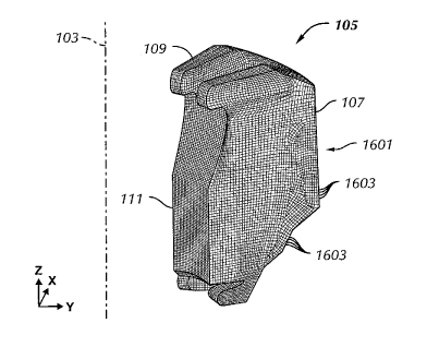
[0057] Further, as shown, seal design 1501 and model or mesh 1601 (discussed
below) may only represent a radial portion of packing unit 105. However, the
remainder of packing unit 105 may be easily generated by taking advantage of
the
syinmetrical geometry of packing unit 105. Those having ordinary skill in the
art
will appreciate that in the case of radially symmetric models, symmetric
portions
and profiles may be used and replicated to sii-nplify the generation of the
model.
[0088] Referring now to Figure 16, seal design 1501 created using CAD software
may be imported into FEA software to generate a model or mesh 1601 of numerous
finite elements 1603. Finite elements 1603 of mesh 1601 work together to
simulate
a seal and a packing unit when stresses and forces are applied. Finite
elements 1603
of elastomeric body 107 of packing unit 105 will simulate and respond to
stress and
forces (i.e., they will exhibit strain) corresponding to the material
properties of the
elastomeric material.
[00$9] Similarly, finite elements 1603 of metal inserts 109 of packing unit
105 will
simulate and respond to stress and forces corresponding to the material
properties of
the metal inserts. Thus, finite eleinents 1603 deform and strain to siinulatE
the
response of the different materials (e.g., elastomers and rigid inater-ials)
of the seal in
accordance with their material properties. While finite elements 1603 are
shown as
eight-noded elements (i.e., brick elements), finite elements of any shape
known in
the art may be used.
[0090] Further, while generating a seal model 1220, a number of smoothing
tecllniclues may be used on the seal desigii 1222, In many circumstances, as
mentioned above, analyzing the actual manufactured geometry of the seal using'
FEA may lead to complications when large amounts of stress and strain are
simulated. Particularly, as manufactured, the geometry of metal seal
components
include radiused corners and other stress-concentration reducing features to
more
evenly distribute stress across the component as it is loaded. However, it has
been
19
CA 02659000 2009-01-22
WO 2008/014517 PCT/US2007/074762
discovered that these techniques may adversely affect FEA models in FEA in
that
they increase the complexity of the model and may prevent the FEA from
producing
accurate results. Therefore, a seal model generated from a smoothed design may
include removing as-manufactured stress concentration features in an effort to
improve the results of FEA.
[0091] ln one embodiment, the seal design's rigid material may be modified
(i.e.,
smoothed) to reduce their complexity. Referring now to Figure 17A, an end view
of
a metal insert 1701 including flanges 1703 connected by a web 1705 is shown.
Metal insert 1701 typically includes radiused internal corners 1707 and
squared
external corners 1709. However, in one embodiment of smoothing a design, the
corners of the metal insert may be modified. For example, referring now to
Figure
17B, an end view of a metal insert 1711 design including flanges 1713
connected by
a web 1715 in accordance with embodiments disclosed herein is shown. In
smoothing the design, internal corners 1717 may be modified to reduce or
eliminate
their radii (as shown) in an atteinpt to simplify a subsequently constructed
rnodel.
Further, in smoothing the seal design, extemal corners 1719 may be modified to
add
or increase their radii (also shown) in an attempt to simplify a subsequently
constructed model. A seal model constructed in this manner may be analyzed for
bulk strains such that the FEA may produce more accurate and definitive
results than
would be possible using the former, more "localized" approach.
[0092] Furthermore, in another embodiment, instead of smoothing the design by
modifying internal and external corners of the rigid material insert, the
smoothing
may include modifying the shape of the rigid material insert and its position
within
the elastomeric body. Referring now to Figure 18A, a top view of a metal
insert
1801 disposed within a poi-tion of an elastomeric body 1802 of an annular
packing
unit is shown. Flange 1803 and web 1805 (outline shown) of metal insert 1801
shown has a rectangular outline, in which flange ends I 804A, 1804B of flange
1 S03
and web ends 1806A, 1806B of web 1805 are defined by straight edges. Ends
1804A, 1806A are radially closer to central axis 103 than ends 1804B, 1806B.
[0093] However, referring to Figure 1 SB, the shape and orientation of the
metal inscrt
may be smoothed for bulk strain analysis. In Figure 18B, a top view of a metal
insert 1811 disposed within a portion of an elastomeric body 1802 of an
annular
packing unit in accordance with embodiinents disclosed herein is sliown. As
shown,
CA 02659000 2009-01-22
WO 2008/014517 PCT/US2007/074762
flange 1813 and web 1815 (outline shown) of metal insert 1811 have arcuate
ends to
define a radial outline centered about central axis 103. Specifically, sides
1814C,
1814D of flange 1813 may follow along radial lines 1817 extending radially out
from central axis 103. Sides 1816C, 1816D of web 1815 may similarly follow
along
radial lines (not shown). With this, flange ends 1814A, 1814B disposed between
flange sides 1814C, 1814D and web ends 1816A, 1816B disposed between web
sides 1816C, 1816D may then follow an arcuate path to have an arc, bow, or
bend,
as shown. Preferably, arcuate ends 1814A, 1814B, 1816A, 1816B follow radial
paths 1818 defined about central axis 103. Thus, as shown, a width of flange
1813
and web 1815 increases when following along their sides 1814C, 1814D, 1816C,
1816D from ends 1814A, 1816A to ends 1814B, 1816B. As such, a seal model
constructed in this manner may be able to more accurately simulate strain
during
FEA to produce more accurate and definitive results.
100941 Further still, the elastomeric body of the seal design may be smoothed
as well.
Referring again to Figure 15, elastomeric body 107 includes a compression face
108
corresponding to wedge face 118 of piston (117 of Figure 1). When piston 117
is
activated, wedge face 118 contacts and compresses packing unit 105 to seal the
well.
in one technique, the seal design may be sinoothed by modifying the
compression
face to have approximately the same angle as the wedge face of the piston.
Alternatively, the wedge and compression faces may be modified to increase a
contact region therebetween. By modifying the coinpression face, the wedge
face,
or both, a seal model consti-ucted therefrom may be able to more accurately
siinuEate
strain for the strain plots during FEA. As the compressive face of the
clastomeric
body would otherwise have a different angle than the wedge face of the piston,
the
output of the FEA may be simplified to produce more accurate or definitive
results
when displaced.
[0095] Those having ordinary skill in the art will appreciate that, in
addition to these
described smoothing techniques and modifications, other techniques may be used
as
well in addition. For exainple, in an.other embodiment, the web of the rigid
material
inser-t may be modified, such as hollowing the web of the insert, as long as
the rigid
material insei-t provides sufficient structural support for the seal to
sustain the forces
applied thereto when under any and all displacen-ient conditions.
21
CA 02659000 2009-01-22
WO 2008/014517 PCT/US2007/074762
[00961 Preferably, when generating the seal models in step 1220, especially
when
smoothing the seal design 1222 of the seal model, the volume of the
elastomeric
body and the rigid material inserts of the seal model remains substantially
constant.
If the volume does not remain constant, the results and simulated strain from
the
strain plots created by the FEA may not be accurate or consistent. For
exan7ple,
when applying a force to an element, the force upon the element will stress
the
eleinent, causing the elernent to strain to accommodate the stress. The stress
applied
to the element, though, is directly proportional to the force applied to the
element
and inversely proportional to the area or voluzne of the element. Thus, if the
force
applied to the element increases and/or the volunie of the element decreases,
the
stress will correspondingly increase in the element.
[0097] Using this concept, the respective volumes of the elastomeric body and
the
rigid material inserts preferably remain substantially constant to provide
accurate
results. For example, if the volume of the overall seal model has
substantially
changed from the actual seal, the strain plots of the seal model may show an
increase
in strain in the elastomeric body with corresponding displacement conditions.
Further, if the volume of the seal model changes from the smoothing
tecllniques
applied to the seal design of the seal model, such as increasing the volume of
the
elastomeric body of the seal model during the smoothing process, the strain
plots of
the si-noothed model may show a decrease in simulated strain with
corresponding
displacement conditions. Tl1us, if the volume of the elastorneric body and the
rigid
material insert of the niodel of the seal increases or decreases, the
simulated strain in
the model would inherently change, independent.if the seal model was modified
for
any iinprovements. Furthermore, if the overall volume of the seal remains
consistent between non-smoothed and srnoothed nlodels but the relative volumes
of
the elastomeric body and the rigid inser-ts cliange, the strain plots may be
similarly
compromised.
[0098] Continuing now with step 1230, displacement conditions are sin-iulated
upon a
seal for a blowout preventer in FEA using the generated seal model.
Preferably, the
simulated displacement conditions are loads and strains the seal may expect to
experience in service. For exainple, a model of a packing unit of an annulai-
blowout
preventer may require a simulated displacement condition correlating to
compressing into a closed position to seal about a section of drillpipe.
Further, if ilo
22
CA 02659000 2009-01-22
WO 2008/014517 PCT/US2007/074762
drillpipe is present, the model may experience a simulated displacement
condition
correlating to compressing to close about itself to seal the bore.
[00991 In step 1240, a strain plot, showing strain and deformation occurring
in the
seal model in response to displacement conditions may be analyzed and reviewed
to
determine the performance of the modeled seal. Refei-ring now to Figures 19-
21,
cross-sectional strain plots of a seal model in accordance with ea-nbodiments
disclosed herein are shown. Specifically, the seal model is of a packing unit
for an
annular blowout preventer, in which packing unit model is initially simulated
with a
displacement condition as closed about a drillpipe 151. Then, the packing unit
is
shown in an original condition before the packing unit is simulated with the
displacement condition, but the strain from the simulated displacement
condition is
superimposed across the non-displaced packing unit. This technique may be
perforined by calculating the strain from each element of the seal model with
the
displacement condition and showing the strain upon each corresponding element
of
the seal model in the original condition. This may allow the strain occurring
in the
packing unit under the simulated displacement condition to be "inapped" back
to its
original location in the packing unit.
[00140] Referring now to Figure 19A, a strain plot of the packing uaiit model
shows
the maximum principal log strain occurring in the seal model with a simulated
displacement condition of closing the packing unit about drillpipe 151. In
Figure
19B, a strain plot of the seal model shows the packing unit originally before
the
displacement condition is si.anulated across the seal inodel in Figure 19A,
but the
maximum principal log strain plot from Figure 19A is superimposed across the
undistorted seal model. Specifically, the strain of each element in the seal
model in
the displacement condition in Figure 19A is added to each elenient in the
undistorted
seal model in Figure 19B. This allows the strain plot to show where the strain
concentrations will be located when in an undisplaced condition.
[00101] Similarly, referring to Figure 20A, a strain plot of the packing unit
inodel
shows the axial log strain occurring in the seal model with a simulated
displacemellt
condition of closing the packing unit about drillpipe 15 1. ln Figure 20B, a
strain
plot of the seal model shows the packing unit originally before the
displacement
condition is simulated across the seal model in Figure 20A, but the axial log
strain
plot from Figure 20A is superimposed across the undistorted seal niodel.
23
CA 02659000 2009-01-22
WO 2008/014517 PCT/US2007/074762
[00102] Similarly still, referring to Figure 21A, a strain plot of the packing
unit model
shows the shear log strain occurring in the seal model with a simulated
displacement
condition of closing the packing unit about drillpipe 151. In Figure 21B, a
strain
plot of the seal model shows the packing unit originally before the
displacement
condition is simulated across the seal model in Figure 21A, but the shear log
strain
plot from Figure 21A is superimposed across the undistorted seal model.
[00103] As shown in Figures 19-21, the packing unit experiences large amounts
of
strain to accoinunodate the closed position simulated displacement condition
simulated with the seal model. Because of these large strains, the finite
elements of
the model or mesh may not deform properly to converge to an accurate or
definitive
result. However, by analyzing a bulk strain plot of a smoothed niodel in step
1240, a
definitive result may be found. FEA focusing on the evaluation of bulk strain
may
be used to produce more accurate results.
[00104] Referring now to Figure 22, a graph displaying strain (y-axis) versus
number
of iterations (x-axis) within FEA in is shown. The simulated strain on the y-
axis is a
inagnitude of the principal strain in a specific direction simulated across a
finite
element of the seal model for a given displacement condition. Further, the
number
of iterations on the x-axis refers to the amount of simulations of FEA used
when
modeling the seal. However, in contrast to the FEA iterations of Figure 11
whereby
the model is iteratively made more localized (i.e., complex), each iteration
of Figure
22 may incrementally sinooth the analyzed model (while maintaining consistent
volume) to make such analysis less complex in nature. As such, as the analysis
progresses froa-n a more localized strain aiialysis (i.e., the left side of
the x-axis) to a
bulk strain analysis (i.e., the right portion of the x-axis), the solution
converges and
is contained within a tolerance band of about 1 %. Specifically, the FEA
solution
may be seen to converge in Figure 11 because when the simulated strain
solution
reaches a solution within the tolerance band, the solution continues to stay
witliin the
tolerance band even as more iterations are continued. Desirably, the simulated
strain
of the seal model may converge within a tolerance of at least about 0.5% of
the
theoretical strain.
[00105] As such, in contrast to what one of ordinary skill in the art would
intuitively
believe, a simplified, sn3oothed model may produce a niore convergent and
accurate
24
CA 02659000 2009-01-22
WO 2008/014517 PCT/US2007/074762
FEA solution than more complex, detailed rnodels. As shown in this embodiment,
the simulated strain produced using FEA correlates with experimentally
obseived
solutions and converges to a definitive and correct result about the
theoretical strain
and within the tolerance band limitations. As the number of iterations
increases (and
as the model is further smoothed), the simuiated strain solution produced by
the
FEA corresponds to the strain found in the seal through empirical testing.
With
these results, bulk strain FEA may provide useful results for simulation of
seals for
blowout preventers to further improve their designs.
[001061 For exaznple, referring now to Figures 27A, 27B, and 28, strain that a
seal
model will sustain when simulated with a displacement condition may be shown
on
a strain plot when still in an undisplaced condition. This technique allows
strains to
be determined within areas and elements of the seal model while still in the
undisplaced condition. In Figure 27A, an enlarged view of a strain plot of a
packir-g
unit model shows the maximum principal log strain occurring in the seal model
with
a simulated displacement condition of closing the packing unit about drillpipe
151.
Three finite elements 2711, 2713, 2715 experiencing strain when simulated
witll the
closed displacemest condition have been marked and identified. In Figure 27B,
an
enlarged view of a strain plot of the seal model shows the packing unit
originally
before the displacement condition is simulated across the seal model in Figure
27A,
but the maximum principal log strain occurring in the seal model from the
displacement condition in Figure 27A is superimposed acr-oss the seal model.
As
clements 2711, 2713, 2715 were marked when in the displacement condition in
Figure 27A, elements 2711, 2713, 2715 may be followed back in Figure 27B to
detennine their original location within the seal model to grapllically
represent the
magnitude and direction of the strains they experience. Figure 28 also shows
the
packing unit seal model and mesh from Figures 27A, 27B with ele-nejits 2711,
2713,
2715. Using this and similar techniques, the areas of the seal model with the
strain
concentrations may be more easily detennined to further improve the design of
the
seal model as necessary.
[0Q1071 Further, when analyzing the strain plot in step 1240, the strain plots
may be
used to certify the seal model for use in a blowout preventer. Specifically,
the strain
plots may be compared against one or more specified criteria to detei-inine if
the
performance of the seal model meets necessary requiremeits. Specified
criteria, for
CA 02659000 2009-01-22
WO 2008/014517 PCT/US2007/074762
example, may include performance requirements, custoiner's requirements, or
even
industry requirements for seals. Furthermore, such criteria may be compared
against
the strain plots of an analyzed seal model to determine if a seal manufacturcd
in
accordance with the model would be in compliance with such requirements. For
example, a customer may require packing units of annular blowout preventers to
be
capablc of experiencing strains in excess of 300%. A strain plot of the seal
model
packing unit in a closed position displacement conditions may then be compared
against the specified criteria to deterrnine if the seal model is capable of
satisfying
such requirements.
[00108] In another example, industry requirements, such as API 16A / ISO
13533:2001, may be used as specified criteria to compare and certify a seal
model.
In particular, API 16A, Section 5.7.2 references a "closure test" for ram-type
blowout preventers, while API 16A, Section 5.7.3 references a closure test for
annular-type blowout preventers. Under API 16A / ISO 13533:2001, a packing
unit
may be required to undergo six closures about the drill pipe and, on a seventh
closure, be capable of effectively sealing against pressure of about 200-300
psi (1.4-
2.1 MPa). Thus, displacement conditions froni industry requirements may be
used
in conjunetion with a simulation to detennine if a seal is capable of
satisfying such
requirements. Using methods and embodiments disclosed herein, the seal model
may then be certified by comparing the strain plots of the seal model against
these
specified criteria.
[001091 If the seal inodel generated in step 1220 and analyzed in step 1240
may be
improved further (e.g., if the model does not ineet the specified criteria),
the method
may loop back to step 1210 to deteiznine material properties for another
material af
the seal, or the method may loop back to step 1220 to have the seal lnodel
regenerated or modified as necessary. This loop of generating the seal model
1220
and analyzing the seal model 1240 may be repeated several times until an
"optimized" seal model is reached.
[001101 In one embodiment, selected portions of an elastomeric body of a
packing unit
znay be de-bonded from the rigid nzaterial inserts w[ien looping back and i-e-
generating the seal model 1220 to reduce to reduce the a-nount and location of
strain. Typically, the elastomeric body is completely bonded to metallic
inserts for
the packing unit to maintain maximum rigidity, as discussed above with respect
to
26
CA 02659000 2009-01-22
WO 2008/014517 PCT/US2007/074762
the prior art. However, if selected portions of the elastomeric body are not
bonded
to the rigid material inserts, this may reduce strain in the elastomer of the
packing
unit when the packing unit is modeled in FEA to show the strain plots.
[00111] Referring now to Figures 23-25, strain plots of a smoothed seal model
having
such selective de-bonding are shown. Specifically, the seal model is of a
packing
unit for an annular blowout preventer, in which packing unit model is
initially
simulated with a displacement condition as closed about a drillpipe 151. Then,
the
packing unit is shown in an original condition before the packing unit is
simulated
with the displacement condition, but the strain from the simulated
displacement
condition is superimposed across packing unit. This technique is similar to
Figures
19-21 from above. However, the elastomeric body of the seal model in Figures
23-
25 is additionally de-bonded from a back surface 109B behind a head 109A of
metal
insert 109.
[00112] Referring now to Figure 23A, a strain plot of the packing unit model
with such
a "selectively de-bonded" elastoineric body shows the iiiaxianum principal log
strain
occurring in the seal niodel with a siinulated displaceinent condition of
closing the
packing unit about drillpipe 151. In Figure 23B, a strain plot of the seal
niodei
shows the selectively de-bonded packing unit niodel originally before the
displacei-nent condition is simulated across the seal model in Figure 23A, but
the
maximum principal log strain plot fi-orn Figure 23A is superimposed across the
undistorted seal model. This allows the strain plot to show where the strain
concentrations will be located when in aii undisplaced condition.
[00113] Similarly, referring to Figure 24A, a strain plot of the packing unit
model with
a selectively de-bonded elastoineric body shows the axial log strain occurring
in the
seal model with a simulated displacement condition of closing the packing unit
about drillpipe 151. In Figure 24B, a sti-ain plot of the seal model shows the
selectively de-bonded packing unit model origiiially before the displacement
condition is simulated across the seal rnodel in Figure 24A, but the axial log
strain
plot from Figure 24A is superimposed across the undistorted seal model.
[00114] Similarly still, referring to Figure 25A, a strain plot of the packing
unit model
with a selectively de-bonded elastomeric body sbows the shear log strain occun-
ing
in. the seal model with a simulated dispiacernent condition of closing the
packing
27
CA 02659000 2009-01-22
WO 2008/014517 PCT/US2007/074762
unit about drillpipe 151. In Figure 25B, a strain plot of the seal model shows
the
selectively de-bonded packing unit model originally before the displacement
condition is simulated across the seal model in Figure 25A, but the shear log
strain
plot from Figure 25A is superimposed across the undistorted seal model
[00115] Each of the strain plots of the packing unit model with a selectively
de-bonded
elastorneric body (i.e., Figures 23-25) indicates less strain than the strain
plots of the
packing unit model without selective de-bonding of the elastomeric body (i.e.,
Figures 19-21). Specifically, the volume of the elastomeric body adjacent to
the
back surface of the head of the rigid 3-naterial insert indicates less strain
in the strain
plots of the seal model when the elastomeric body is de-bonded from the rigid
material insert. Thus, as sliown with the selectively de-bonded packing unit,
the seal
model may be modified and re-generated to produce an optiinized seal model
that
reduces the location and amount of strain occurring in the seal model.
[00116] Similar to above with respect to gealerating a seal model in step
1220, when
sirnulating displacement conditions across the seal models 1230, it is
preferable for
the volumes of the seal model and its components to remain substantially
constant.
If the voluines do not remain constant, the results of the straizi plots and
simulated
strain in FEA may not correlate with experimentally observed results or with
one
another, thereby providing inaccurate results. For example, if the volume of
the seal
models of the packing units shown in the straiai plots of Figures 19-21
changes from
the volume of the seal models of the packing units shown in. the strain plots
of
Figures 23-25, it would be difficult to conlpare the strain plots because of
the added
factor of the changing volume. As the volume of the seal model of the packing
unit
increases or decreases, the siinulated strain in the packing unit inherently
changes,
independent if the seal model was iriodified for any improvements.
[00117] In step 1250, after being generated, analyzed, aild possibly re-
generated (if
necessary), the seal model may be used to manufacture a seal for a blowout
preventer 1250. Specifically, using techiiigues known in the art, a seal based
upon
the three-dimensional seal n-iodel may be manufactured for use in a blowout
preventer, such as a packing unit for an aniiular blowout preventer or a top
seal or
variable bore ram packer a rain blowout preventer. For example, the seal model
of
the packing unit for the annular blowout preventer baving selective de-
bonding, as
discussed above and sllown in Figures 23-25, may be manufactured for use in
the
28
CA 02659000 2009-01-22
WO 2008/014517 PCT/US2007/074762
industry. The selective de-bonding packing unit generated in FEA reduced the
strain
concentrations in the packing unit when in the closed position, as coxnpared
to the
packing unit shown in Figures 19-21. This selective de-bonding seal model may
then be manufactured for use or testing within a blowout preventer because of
its
improved performance over the other packing unit shown from the FEA.
100118] Aspects of embodiments disclosed herein, such as generating and
analyzing a
seal model of a seal for a blowout preventer using FEA, may be implemented on
any
type of computer regardless of the platfoi-m being used. For exalnple, as
shown in
Figure 26, a networked computer system 3060 that may be used in accordance
with
an embodiment disclosed h.erein includes a processor 3062, associated memory
3064, a storage device 3066, and numerous other elements and functionalities
typical of today's computers (not shown). Networked computer 3060 may also
include input means, such as a keyboard 3068 and a mouse 3070, and output
means,
such as a monitor 3072. Networked computer system 3060 is connected to a local
area network (LAN) or a wide area network (e.g., the internet) (not shown) via
a
network interface connectioti (not shown). Those skilled in the art will
appreciate
that these input and output means may take many other forms. Additionally, the
computer system may not be coilnected to a network. Fui-ther, those skilled in
the
art will appreciate that one or more elements of aforementioned computer 3060
may
be located at a remote location and connected to the other elements over a
network.
[00119] Advantageously, naetliods ajid embodiments disclosed herein may
provide
improved and iriore accurate i-esults when using FEA. Methods and embodiments
disclosed herein use strain within FEA to deterniine the perforinance
characteristics
of seals for blowout preventers under simulated displacement conditions. This
allows the finite elements within the seal model to displace when
accoinmodating
large amounts of strain.
1001201 Further, methods and embodiments disclosed herein may provide
techniques
for analyzing, smoothing, simplifying, and modifying seal models for use in
FEA.
Using these techniques, the accuracy of the results of the strain plots
created using
FEA may be improved. Additionally, using thcse techniques, the seal model may
be
modified to reduce the amount and location of strain (e.g., strain
concentrations)
occurring in the seal model from the simulated strain plots.
29
CA 02659000 2009-01-22
WO 2008/014517 PCT/US2007/074762
[00121] Furthermore, methods and einbodiments disclosed herein may provide for
a
seal for a blowout preventer with an increased working lifespan. For example,
the
packing unit may be modeled with simulated displacement conditions of repeated
closures (i.e., repeatably closing the seal about a drillpipe or itself) to
determine
design features that may extend the working lifespan (i.e., number of
closures) of the
packing unit.
[001221 While the invention has been described with respect to a limited
number of
embodiments, those skilled in the art, having benefit of this disclosure, will
appreciate that other embodiments may be devised which do not depart from the
scope of the invention as disclosed herein. Accordingly, the scope of the
invention
should be limited only by the attached claii-ns.