Language selection

Search

Patent 2659139 Summary

Third-party information liability

Some of the information on this Web page has been provided by external sources. The Government of Canada is not responsible for the accuracy, reliability or currency of the information supplied by external sources. Users wishing to rely upon this information should consult directly with the source of the information. Content provided by external sources is not subject to official languages, privacy and accessibility requirements.

Claims and Abstract availability

Any discrepancies in the text and image of the Claims and Abstract are due to differing posting times. Text of the Claims and Abstract are posted:

  • At the time the application is open to public inspection;
  • At the time of issue of the patent (grant).
(12) Patent: (11) CA 2659139
(54) English Title: RAILWAY FREIGHT CAR TRUCK
(54) French Title: BOGIE DE WAGON A MARCHANDISES
Status: Granted
Bibliographic Data
(51) International Patent Classification (IPC):
  • B61H 13/36 (2006.01)
  • B61F 3/00 (2006.01)
  • B61H 13/00 (2006.01)
(72) Inventors :
  • WIKE, PAUL S. (United States of America)
(73) Owners :
  • AMSTED RAIL COMPANY, INC. (United States of America)
(71) Applicants :
  • AMSTED RAIL COMPANY, INC. (United States of America)
(74) Agent: GOWLING WLG (CANADA) LLP
(74) Associate agent:
(45) Issued: 2011-05-03
(22) Filed Date: 2009-03-10
(41) Open to Public Inspection: 2010-04-06
Examination requested: 2009-03-10
Availability of licence: N/A
(25) Language of filing: English

Patent Cooperation Treaty (PCT): No

(30) Application Priority Data:
Application No. Country/Territory Date
12/287020 United States of America 2008-10-06

Abstracts

English Abstract

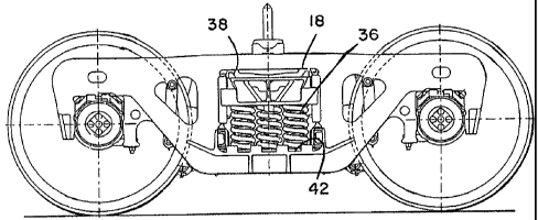
An improved railway car truck is provide that includes two sideframes and a bolster. The bolster has laterally opposite ends, each end extending into and supported within a sideframe opening on a spring group. Each sideframe also has a pedestal opening at each end to receive a bearing adapter assembly. The railway car truck also includes two brake beam assemblies supported on the railway car truck bolster and sideframes. Each brake beam assembly includes an elongated main section, a support section, and a standoff section extending between the main section and support section. Two brake hangers comprised of a leg sections and a bottom section support an end of the brake beam assembly. The brake hangers can be reversed such that the brake head support sections can be spaced laterally to adapt to different rail gauges. Further, an improved center plate is provided on an upper surface of the bolster, wherein the center plate includes a center plate liner which is comprised of a circular disk of austempered ductile iron.


French Abstract

L'invention porte sur un bogie de wagon ferroviaire qui comprend deux cadres latéraux et une traverse dansante. La traverse dansante comprend deux extrémités opposées de manière latérale, chaque extrémité se prolongeant dans une ouverture du cadre latéral et à l'intérieur de ce dernier sur un groupe de ressorts. Chaque cadre latéral comprend aussi une ouverture de plaque de garde à chaque extrémité pour recevoir un ensemble adaptateur de palier. Le bogie de wagon ferroviaire comprend aussi deux ensembles de poutre-frein soutenus sur la traverses dansante du bogie de wagon ferroviaire et les wagons latéraux. Chaque ensemble de poutre-frein comprend une section principale allongée, une section de soutien et une section de distance se prolongeant entre la section principale et la section de soutien. Deux bielles de suspension de porte-semelle comprenant des sections de jambe et une section inférieure soutiennent une extrémité de l'ensemble poutre-frein. Les bielles de suspension de porte-semelle peuvent être inversées de façon que les section de soutien du porte-semelle de frein peuvent être espacées latéralement afin de s'adapter à différents écartements de voie. De plus une plaque centrale améliorée est fournie sur la surface supérieure de la traverse dansante, où la plaque centrale comprend une doublure de plaque centrale qui est constituée d'une disque circulaire de fonte bainitique (ADI : (Austempered Ductile Iron).

Claims

Note: Claims are shown in the official language in which they were submitted.


CLAIMS

What is claimed is:


1. A railway car truck comprising

two sideframes, each sideframe having a pedestal formed on longitudinally
opposite ends
thereof and substantially upright columns defining a sideframe opening
intermediate the
pedestals,

a vertical surface on each column, each pedestal having a pedestal opening,

a bolster transverse relative to the sideframes and having laterally opposite
ends, each end
extending into and supported within a sideframe opening,

the bolster also including two laterally spaced side bearing pads on an upper
surface of
the bolster between the sideframes,

a side bearing on each side bearing pad,

a spring group in each sideframe opening that supports a respective end of the
bolster,
a friction show having two spaced sloped surfaces disposed between the bolster
and the
vertical surface of a column of a sideframe,

the sloped surface of the friction shoe forcing a complementary sloped surface
of the
bolster,

and the friction shoe having a vertical wall facing the vertical surface of a
column of a
sideframe,

a bearing adapter and an elastomeric adapter pad received in each pedestal
opening of
each sideframe,

two brake beam assemblies supported on the railway car truck bolster and
sideframes,

~10~


each brake beam assembly comprising an elongated main section having two end
portions,

a support section extending from the elongated main section near each end
portion at an
acute angle,

a standoff section extending between a center portion of the elongated main
section to a
center portion of the support section,

two brake hangers each comprised of two leg sections and a bottom section
joining the
leg sections, the brake hanger supported from one of the sideframes,

the brake hangers supporting the elongated main section of the brake beam
assembly near
each end portion thereof,

two brake heads each having a support section,

the brake head support section being affixed to one of the end portions of the
elongated
main section of the brake beams,

the two brake head support sections being spaced laterally apart to adapt to a
first rail
gauge,

and wherein one or both brake hangers can be reversed such that the two brake
head
support sections are spaced laterally apart to adapt to a second rail gauge.


2. The railway car truck of claim 1

further comprising a brake head pin, wherein each brake head support section
includes a pin opening,

and each brake head support section is affixed to one of the end portions of
the
elongated main section of the brake beam by a brake head pin.


~11~


3. The railway car truck of claim 1

wherein each brake hanger is comprised of two leg sections,

wherein each leg section includes a support opening at an end of each leg
section,
and wherein one of the leg sections intersects with the bottom section
approximately
at a right angle and the other leg section intersects with the bottom section
at an acute
angle,

whereby, when one or both of the brake hangers are reversed in hanging from
its
support openings at the end of each leg section, the rail gauge between the
brake head
support sections is changed.


4. The railway car truck of claim 1

further comprising a load beam support extending laterally inward from a top,
portion
of each sideframe,

and a load beam extending laterally between the two sideframes,

the load beam having two ends, each end affixed to one of the load beam
supports on
a sideframe.


5. The railway car truck of claim 1

further comprising a circular center plate on an upper surface of the bolster,
the center
plate located at a portion midway between the laterally opposite ends of the
bolster,
and a center plate liner comprised of a circular disk of austempered ductile
iron
having a Brinell hardness of 340.


~12~


6. A railway car truck comprising

two sideframes, each sideframe having a pedestal formed on longitudinally
opposite
ends thereof and substantially upright columns defining a sideframe opening
intermediate the pedestals,

a vertical surface on each column,

each pedestal having a pedestal opening,

a bolster transverse relative to the sideframes and having laterally opposite
ends, each
end extending into and supported within a sideframe opening,

the bolster also including two laterally spaced side bearing pads on an upper
surface
of the bolster between the sideframes,

a side bearing on each side bearing pad,

a spring group in each sideframe opening that supports a respective end of the
bolster,
a friction shoe having two spaced sloped surfaces disposed between the bolster
and
the vertical surface of a column of a sideframe,

the sloped surface of the friction shoe facing a complementary sloped surface
of the
bolster,

and the friction shoe having a vertical wall facing the vertical surface of a
column of a
sideframe,

a bearing adapter and an elastomeric adapter pad received in each pedestal
opening of
each sideframe,

two brake beam assemblies supported on the railway car truck bolster and
sideframes,
each brake beam assembly comprising an elongated main section having two end
portions,


~13~


a support section extending from the elongated main section near each end
portion at
an acute angle,

a standoff section extending between a center portion of the elongated main
section to
a center portion of the support section,

two brake hangers each comprised of two leg sections and a bottom section
joining
the leg sections, the brake hanger supported from one of the sideframes,

the brake hangers supporting the elongated main section of the brake beam
assembly
near each end section thereof,

two brake heads each having a support section,

the brake head support section being affixed to one of the end portions of the

elongated main section of the brake beam,

the two brake head support sections being spaced laterally apart to adapt to a
first rail
wheel gauge,

and wherein one or both brake hangers can be reversed such that the two brake
head
support sections are spaced laterally apart to adapt to a second rail wheel
gauge,
wherein each brake hanger is comprised of two leg sections,

wherein each leg section includes a support opening at an end of each leg
section,
and wherein one of the leg sections intersects with the bottom section
approximately
at a right angle and the other leg section intersects with the bottom section
at an acute
angle,

whereby when one or both of the brake hangers are reversed in hanging from its

support openings at the end of each leg section, the rail wheel gauge between
the
brake head support section is changed.


~14~


7. The railway car truck of claim 6

further comprising a brake head pin, wherein each brake head support section
includes a pin opening,

and each brake head support section is affixed to one of the end portions of
the
elongated main sections of the brake beam by a brake head pin.


8. The railway car truck of claim 6

further comprising a load beam support extending laterally inward from a top
portion
of each sideframe,

and a load beam extending laterally between the two sideframes,

the load beam having two ends, each end affixed to one of the load beam
supports on
a sideframe.


9. The railway car truck of claim 6

further comprising a circular center plate on an upper surface of the bolster,
the center
plate located at a portion midway between the laterally opposite ends of the
bolster,
and a center plate liner comprised of a circular disk of austempered ductile
iron
having a Brinell hardness of 340.


10. A railway car truck comprising


~15~


two sideframes, each sideframe having a pedestal formed on longitudinally
opposite
ends thereof and substantially upright columns defining a sideframe opening
intermediate the pedestals,

a vertical surface on each column, each pedestal having a pedestal opening,

a bolster transverse relative to the sideframes and having laterally opposite
ends, each
end extending into and supported within a sideframe opening,

the bolster also including two laterally spaced side bearing pads on an upper
surface
of the bolster between the sideframes,

a spring group in each sideframe opening that supports a respective end of the
bolster,
two brake beam assemblies supported on the railway car truck bolster and
sideframes,
each brake beam assembly comprising an elongated main section having two end
portions,

a support section extending from the elongated main section near each end
portion at
an acute angle,

a standoff section extending between a center portion of the elongated main
section to
a center portion of the support section,

two brake hangers each comprised of two leg sections and a bottom section
joining
the leg sections, the brake hanger supported from one of the sideframes,

the brake hangers supporting the elongated main section of the brake beam
assembly
near each end portion thereof,

two brake heads each having a support section,

the brake head support section being affixed to one of the end portions of the

elongated main section of the brake beam,


~16~


the two brake head support sections being spaced laterally apart to adapt to a
first rail
gauge,

and wherein one or both brake hangers can be reversed such that the two brake
head
support sections are spaced laterally apart to adapt to a second rail gauge.


11. The railway car truck of claim 10

further comprising a brake head pin, wherein each brake head support section
includes a pin opening,

and each brake head support section is affixed to one of the end portions of
the
elongated main section of the brake beam by a brake head pin.


12. The railway car truck of claim 10

wherein each brake hanger is comprised of two leg sections,

wherein each leg section includes a support opening at an end of each leg
section,
and wherein one of the leg sections intersects with the bottom section
approximately
at a right angle and the other leg section intersects with the bottom section
at an acute
angle,

whereby, when one or both of the brake hangers are reversed in hanging from
its
support openings at the end of each leg section, the rail gauge between the
brake head
support section is changed.


~17~


13. The railway car truck of claim 10

further comprising a load beam support extending laterally inward from a top
portion
of each sideframe,

and a load beam extending laterally between the two sideframes,

the load beam having two ends, each end affixed to one of the load beam
supports on
a sideframe.


14. The railway car truck of claim 10

further comprising a circular center plate on an upper surface of the bolster,
the center
plate located at a portion midway between the laterally opposite ends of the
bolster,
and a center plate liner comprised of a circular disk of austempered ductile
iron
having a Brinell hardness of 340.


~18~

Description

Note: Descriptions are shown in the official language in which they were submitted.


. i . .... . . . . ... . .. . ..... . . ._ ... .. .. . .. .
CA 02659139 2000-03-10

Case: ASF022
RAILWAY FREIGHT CAR TRUCK

BACKGROUND OF THE INVENTION

The present invention relates to a railway freight car truck and, more
particularly, to an
improved railway freight car truck having a brake beam adaptable for differing
rail gauges.

In a railway freight car truck, two axles are held in a pair of laterally
spaced sideframes,
with a bolster extending laterally between and supported on each sideframe.
The wheels are
press fit on the axles, with the ends of the axles also fitted with a roller
bearing assembly. The
roller bearing assembly itself is fit into a bearing adapter that is fit into
a pedestal jaw opening at
the longitudinal end of each sideframe. The ends of the bolsters are
themselves supported on

spring groups, which are supported on the lower portion of the center openings
of the sideframes.
A bearing adapter and pad assembly can also be provided that is useful in the
fitting of
the roller bearing assembly into the pedestal jaw opening of each sideframe.
The bearing
adapter, which is itself fit on top of the bearing assembly, is comprised of a
unitary cast steel
piece. An elastomeric adapter pad is fitted on top of the bearing adapter.

Two side bearings are also typically provided in an upper surface of the
bolster to assist
in supporting a car bolster that is part of the structure of the freight car.

Each railway freight car truck also includes two brake beams that act to
transmit braking
force through brake shoes to the outer tread of the railway wheels.

It is an object of the present invention to provide an improved railway truck
having a
brake beam support that can adapt to different rail gauges.

SUMMARY OF THE INVENTION

A railway freight car truck of the so-called three piece standard design, is
comprised of
two laterally spaced, unitary cast steel sideframes and a laterally extending
bolster, also of a
~1~


CA 02659139 2000-03-10

Case: ASF022
unitary cast steel structure. The ends of the bolster are received and
supported on spring groups
25 that themselves are supported on the bottom section of a bolster opening in
each sideframe.

The wheel axle assemblies themselves are received in openings, commonly
referred to as
pedestal jaw openings, at longitudinal ends of each sideframe. The wheel axle
assemblies
themselves extend laterally between the sideframes, and hence, also laterally
between the two
spaced railway tracks. For improved performance of the railway freight car
truck, it is desirable

30 to receive the bearings press fit on each axle end into a bearing adapter
assembly. Each railway
car truck includes two brake beam assemblies. Each brake beam assembly is
comprised of a
main section and a support section. Two brake hangers support the main section
of the brake
beam assembly. The brake hangers can be reversed in order to allow the brake
beam assembly to
adapt to different rail gauges.

35 BRIEF DESCRIPTION OF THE DRAWINGS
In the drawings,

Fig. I is a side view of a first embodiment of a railway car truck in
accordance with the
present invention;

Fig. 2 is a top view of the first embodiment of a railway car truck in
accordance with the
40 present invention;

Fig, 2A is a perspective view of a first embodiment of railway car truck in
accordance
with the present invention;

Fig. 3 is an end view, in partial cross section, of the first embodiment of a
railway car
truck in accordance with the present invention;

45 Fig. 4 is a top view of a first embodiment of a brake beam assembly in
accordance with
the present invention;

-2-


CA 02659139 2000-03-10

Case: ASF022
Fig. 5 is a perspective view of a first embodiment of a brake head in
accordance with the
present invention;

Fig, 6 is a partial in partial cross section of the first embodiment of a
railway car truck in
50 accordance with the present invention showing a load beam;

Fig. 7 is a detailed view of the first embodiment of a railway car truck in
accordance with
the present invention showing the load beam connection to the sideframe;

Fig. 8 is a side view of a first embodiment of a sideframe in accordance with
the present
invention;

55 Fig. 9 is a top view of the first embodiment of a sideframe in accordance
with the present
invention;

Fig. 10 is a partial detailed view of the first embodiment of a sideframe in
accordance
with the present invention;

Fig. 11 is an exploded view of a first embodiment of a side bearing in
accordance with
60 the present invention;

Fig. 12 is a perspective view of a first embodiment of a brake beam assembly
showing
two main section groups in accordance with the present invention;

Fig. 13 is a partial view of the first embodiment of a brake beam assembly
mounted in a
railway car truck;

65 Fig. 14 is a detailed partial view of a first embodiment of a brake beam
assembly in
accordance with the present invention;

Fig. 15 is a partial detailed of a first embodiment of a hanger in a reversed
position in
accordance with the present invention;

~3-


CA 02659139 2000-03-10

Case: ASF022
Fig. 16 is a perspective view of a brake head mounted on a main section of the
brake

70 beam assembly in accordance with the first embodiment of the present
invention;

Fig. 17 is an exploded view of a first embodiment of a spring group with
friction shoes
and wear plates in accordance with the present invention;

Fig. 18 is a partial perspective view of a first embodiment of a railway car
truck including
a bearing adapter and adapter pad in accordance with the present invention;

75 Fig. 19 is a perspective assembled view of a first embodiment of a bearing
adapter and
adapter pad in accordance with the present invention;

Fig. 20 is a top view of a first embodiment of a bolster center plate wear
liner in
accordance with the present invention, and

Fig. 21 is a side cross sectional view of a first embodiment of a bolster
center plate wear
80 liner in accordance with the present invention.

DETAILED DESCRIPTION OF THE INVENTION

Referring now to Figs. 1-3, a railway truck is show generally at 10. Railway
truck 10 is
seen to comprise two laterally spaced sideframes 12 and 14, between which
bolster 16 extends.
85 Bolster 16 is seen to include bolster ends 32 and 34, which extend through
sideframe openings

18. Spring group 36, shown in detail in Fig. 17, is seen to support bolster
end 32 on sideframe
lower support 42.

Each of sideframes 12 and 14 and bolster 16 are usually a cast steel unitary
structure.
Various internal ribs and supports lend strength, along with a savings in
overall weight for each
90 of such cast steel truck components.

~4-


CA 02659139 2000-03-10

Case: ASF022
Bolster 16 is also seen to include on its upper surface a bolster center plate
64, which
itself includes a bolster center plate wear liner 66. Also included on the
upper surface of bolster
16 are a pair of laterally spaced sidebearings 70.

Axles 20 and 22 extend laterally between sideframes 12 and 14. Railway wheels
11 are
95 press fit on the ends of axles 20 and 22.

Referring now to Fig. 4 brake beam assembly 110 is supported from sideframes
12 and
14 and bolster 16. Brake beam 110 is seen to be comprised of main section 126
which is
generally elongated and extends laterally between sideframes 12 and 14. Brake
beam section
support section 128 is seen to extend at an acute angle from ends of brake
beam main section

100 126. Standoff section 112 extends from a center portion of brake beam main
section 126 to the
apex of curved or bent brake beam support section 128.

Brake beam assembly 110 is typically comprised of structural steel main
section 126
typically in the form of a hollow structural steel section, as is brake beam
support section 128.
Standoff section 114 is typically a fabricated structural steel component.

105 Referring now to Figs. 6 and 7, a partial cross sectional view of railway
truck 10 is
shown. Sideframes 12 and 14 are shown in general cross section, with a
sideframe load beam
support 13 extending from a top section of sideframe 12 with a similar
sideframe load beam
support extending from the top section of sideframe 14. A structural steel
load beam 15 extends
laterally between the sideframe side load beam support. Load beam 15 is seen
to comprise an

110 end section having an opening adapted to receive load beam bolt 117. Load
beam bolt 117
extends through a complementary opening in sideframe load beam support 13. An
appropriate
locking nut or similar fastening device 119 is seen to be affixed to load beam
bolt 117.

~5-


CA 02659139 2000-03-10

Case: ASF022
Referring now to Figs. 8-10, sideframe 14 is shown in detail as a stand alone
structure.
Again, sideframe 14, as well as sideframe 12 and bolster 16 are typically cast
steel unitary

115 devices, with internal ribs and supports to allow the strength necessary
for the structural
components of a railway freight car truck 10 while providing a generally lower
weight structure.
Sideframe 14 is seen to include vertical columns 44 that are longitudinally
spaced and form
sideframe opening 18 there between. Sideframe column vertical face 46 is also
adapted to
receive a sideframe column wear plate 19, which is typically affixed by bolts.
Sideframe 14 is

120 also seen to comprise a lower support section 42, which has various raised
structures adapted to
position spring group 36 thereupon.

Sideframe 14 is also seen to have laterally spaced pedestal jaws 24 which are
the further
most lateral extent of sideframe 14. Each pedestal jaw 24 forms a pedestal jaw
opening, which is
comprised of a roof section 28, an outer wall 26, and inner wall 29. Pedestal
jaw opening is

125 adapted to receive a bearing adapter therein.

Referring now to Fig. 11, side bearing is generally shown at 70. Side bearing
70 is seen to
comprise a base section 72, which is typically unitary steel or iron
structure, having outer walls
forming a generally circular inner opening. Coil spring 76, which can include
one or more inner
springs, is fitted within the opening in side bearing base 72. Side bearing
cap 74 is a unitary steel

130 or iron structure adapted to receive various side bearing coil springs 76
there within. In some
embodiments, side bearing springs 76 are a combination of coil springs and
solid elastomer
springs. As described previously, side bearings 70 are located on a top
surface of bolster 16.

Referring now to Figs. 12-16, the detailed views of brake beam assembly 110
are shown.
Brake beam assembly 110 is seen to be comprised of elongated structural brake
beam main

135 section 126 and support section 128 which is seen to extend at acute
angles from each end of
~6-

. .._ . .. ... .. . . . . ... .... . ...... ......._.. ,._ _. .. _.. ....... .
.. . .. . ..
CA 02659139 2000-03-10

Case: ASF022
brake beam main section 126. Standoff 114 extends from center portion of brake
beam main
section 126 to the apex of the bent portion of brake beam support section 128.
An operating lever
112, which is generally comprised of two spaced structural steel components,
extends
downwardly and is affixed to standoff 114 and to operating lever 117.

140 Laterally spaced hangers 122 and 124 are seen to support the ends of brake
beam main
section 126. Each of brake beam hangers 122 and 124 is seen to be comprised of
a generally
cylindrical bent steel structure, having two leg portions 142 and 144 of which
leg portion 142 is
generally transverse to brake beam main section 126 whereas leg portion 144
extends at an acute
angle from brake beam main section 126. A joining section 146 is seen to join
leg sections 142

145 and 144. Each of leg sections 142 and 144 is seen to end in openings
adapted to receive hanger
support pins 132 and 134.

Brake head 116 is seen to be a fabricated or cast steel device adapted to
receive a brake
shoe 117. Brake head 116 is adapted to be received on an end portion of brake
beam main
section 126. Brake head 116 has an opening as does brake beam main section 126
to receive

150 brake pin retainer 120. As can be seen from Figs. 14 and 15, brake hanger
122 can be reversed.
In Fig. 14, the lateral space between a center line of brake head 116 is seen
to be a distance A.
Upon the reversing of brake hanger 122, the lateral space between brake head
116 seem to be
reduced to a distance B. The distances A and B correspond to two different
rail gauges; thereby it
is seen that by reversing one or both of brake hangers 122 or 124, the lateral
space between brake

155 heads 116 can be adjusted from a lateral distance A to a lateral distance
B to thereby adapt the
brake assembly 110 to be operative between two different rail gauges.

Referring now to Fig. 17, details of the spring group 36 and other suspension
components
are shown. As previously explained, spring group 36 is supported on sideframe
lower support 42.
~7-


CA 02659139 2000-03-10

Case: ASF022
In turn, spring group 36 supports an end 32 of bolster 16. Friction wear
plates 19 are seen in

160 previously described to be affixed to vertical wall surfaces of sideframe
columns 44. Also shown
are friction shoes 38. Friction shoes 38 and 40 are each seen to comprise two
spaced sloped
surfaces 43 and 45, a top intersection portion 41, and a rear or vertical face
62. Rear or vertical
face 62 is designed to contact sideframe column wear plate 19 and thereby
provide damping to
bolster 16 while supported on spring group 36.

165 Referring now to Figs. 18 and 19, a partial view of railway truck 10 is
shown with bolster
12 having its end 32 extending into sideframe opening 18 in sideframe 14.
Spring group 36
supports bolster end 32. The lateral end of bolster 14 forms pedestal jaw 24,
which itself forms a
pedestal opening. Pedestal opening is formed by an outer wall of pedestal jaw
24, roof section
28, and inner wall 29. Bearing adapter 80 is seen to be comprised of a
unitary, steel or iron

170 structure. Bearing adapter 80 is seen have a generally rectangular top
section 80, depending
shoulders 84 and 86 which extend downwardly there from with a space there
between. Also
formed in bearing adapter 80 is an arcuate opening 89 into which an end of
axle 20 is fit.

Bearing adapter 80 also is seen to comprise raised edge supports 88 which
extend
upwardly at lateral edges of bearing adapter 80. A unitary adapter pad 92 is
seen to be of a
175 generally rectangular shape. Adapter pad 92 is seen to have an adapter pad
top 94 which is a

generally rectangular structure, and adapter pad depending legs 96 and 98
which are spaced
laterally which fit inside depending shoulder 84 and 86 of bearing adapter 80.
Accordingly,
adapter pad 92 is seen to fit on top of bearing adapter 80. Adapter pad
lateral edge 99 is seen to
fit against raised edge support 88 of bearing adapter 80 thereby inhibiting
the lateral movement

180 of adapter 92 on top of bearing adapter 80. Adapter pad 92 again is a
unitary structure usually of
8 -

. ... : ... .. . . . . . . . . . .. . _ . .. ........ . . .. .
CA 02659139 2000-03-10

Case: ASF022
a selected elastomer or similar material. Adapter pad 92 assembled on bearing
adapter 80 are
shown in Fig. 19.

Referring now to Figs. 20 and 21, bolster center plate liner is shown
generally at 66.
Bolster center plate liner 66 is seen to be a cylindrical or disk shaped
structure which fits inside
185 bolster center plate 64. Bolster center plate wear liner 66 is generally
comprised of an

austempered ductile iron structure, generally having a Brinell hardness of
340. Bolster center
plate wear liner 66 assists in the capacity of railway car truck 10 being able
to negotiate curves
with some movement of axles 20 and 22 from a parallel position. Such turning
capability of
railway car truck 10 is also greatly assisted by the structure previously
described of bearing
190 adapter 80 and adapter pad 92.

~9-

Representative Drawing
A single figure which represents the drawing illustrating the invention.
Administrative Status

For a clearer understanding of the status of the application/patent presented on this page, the site Disclaimer , as well as the definitions for Patent , Administrative Status , Maintenance Fee  and Payment History  should be consulted.

Administrative Status

Title Date
Forecasted Issue Date 2011-05-03
(22) Filed 2009-03-10
Examination Requested 2009-03-10
(41) Open to Public Inspection 2010-04-06
(45) Issued 2011-05-03

Abandonment History

There is no abandonment history.

Maintenance Fee

Last Payment of $624.00 was received on 2024-02-20


 Upcoming maintenance fee amounts

Description Date Amount
Next Payment if standard fee 2025-03-10 $624.00
Next Payment if small entity fee 2025-03-10 $253.00

Note : If the full payment has not been received on or before the date indicated, a further fee may be required which may be one of the following

  • the reinstatement fee;
  • the late payment fee; or
  • additional fee to reverse deemed expiry.

Patent fees are adjusted on the 1st of January every year. The amounts above are the current amounts if received by December 31 of the current year.
Please refer to the CIPO Patent Fees web page to see all current fee amounts.

Payment History

Fee Type Anniversary Year Due Date Amount Paid Paid Date
Request for Examination $800.00 2009-03-10
Registration of a document - section 124 $100.00 2009-03-10
Application Fee $400.00 2009-03-10
Final Fee $300.00 2011-02-17
Maintenance Fee - Application - New Act 2 2011-03-10 $100.00 2011-02-25
Maintenance Fee - Patent - New Act 3 2012-03-12 $100.00 2012-02-17
Maintenance Fee - Patent - New Act 4 2013-03-11 $100.00 2013-02-18
Maintenance Fee - Patent - New Act 5 2014-03-10 $200.00 2014-03-03
Maintenance Fee - Patent - New Act 6 2015-03-10 $200.00 2015-03-09
Maintenance Fee - Patent - New Act 7 2016-03-10 $200.00 2016-03-07
Maintenance Fee - Patent - New Act 8 2017-03-10 $200.00 2017-03-06
Maintenance Fee - Patent - New Act 9 2018-03-12 $200.00 2018-03-05
Maintenance Fee - Patent - New Act 10 2019-03-11 $250.00 2019-02-21
Maintenance Fee - Patent - New Act 11 2020-03-10 $250.00 2020-02-21
Maintenance Fee - Patent - New Act 12 2021-03-10 $255.00 2021-02-18
Maintenance Fee - Patent - New Act 13 2022-03-10 $254.49 2022-02-18
Maintenance Fee - Patent - New Act 14 2023-03-10 $263.14 2023-02-22
Maintenance Fee - Patent - New Act 15 2024-03-11 $624.00 2024-02-20
Owners on Record

Note: Records showing the ownership history in alphabetical order.

Current Owners on Record
AMSTED RAIL COMPANY, INC.
Past Owners on Record
WIKE, PAUL S.
Past Owners that do not appear in the "Owners on Record" listing will appear in other documentation within the application.
Documents

To view selected files, please enter reCAPTCHA code :


To view images, click a link in the Document Description column. To download the documents, select one or more checkboxes in the first column and then click the "Download Selected in PDF format (Zip Archive)" or the "Download Selected as Single PDF" button.

List of published and non-published patent-specific documents on the CPD .

If you have any difficulty accessing content, you can call the Client Service Centre at 1-866-997-1936 or send them an e-mail at CIPO Client Service Centre.


Document
Description 
Date
(yyyy-mm-dd) 
Number of pages   Size of Image (KB) 
Abstract 2000-03-10 1 27
Cover Page 2010-03-30 1 54
Representative Drawing 2010-03-31 1 19
Description 2000-03-10 9 359
Claims 2000-03-10 9 260
Drawings 2000-03-10 8 266
Claims 2010-09-27 9 261
Cover Page 2011-04-07 1 54
Assignment 2000-03-10 6 135
Correspondence 2009-04-20 1 16
Prosecution-Amendment 2009-07-08 1 32
Correspondence 2010-05-20 1 14
Prosecution-Amendment 2010-06-04 1 29
Prosecution-Amendment 2010-09-27 11 313
Correspondence 2011-02-17 2 49
Prosecution Correspondence 2000-03-10 2 53