Note: Descriptions are shown in the official language in which they were submitted.
CA 02659199 2009-01-27
WO 2008/024812 PCT/US2007/076471
INFUSION MEDIUM DELIVERY DEVICE AND METHOD WITH COMPRESSIBLE
OR CURVED RESERVOIR OR CONDUIT
CROSS-REFERENCE TO RELATED PATENT APPLICATIONS
[0001] The present invention is related to U.S. Patent Application No.
11/588,847,
filed October 27, 2006 (attorney docket no. 0390), which is incorporated
herein by reference in
its entirety. In addition, the present invention relates to U.S. Provisional
Patent Application
60/839,832, filed August 23, 2006, titled Infusion Medium Delivery Device And
Method With
Compressible Or Curved Reservoir Or Conduit," which is incorporated herein by
reference in
its entirety and from which a priority filing date is claimed. The present
invention also relates
to U.S. Patent Application 60/678,290, filed 5/6/2005 and U.S. Patent
Application No.
11/211,095, filed 8/23/05, titled "Infusion Device And Method With Disposable
Portion," each
of which is incorporated herein by reference in its entirety. The present
invention also relates
to co-pending application no 60/839,821, filed 8/23/2006, titled "Systems And
Methods
Allowing For Reservoir Filling And Infusion Medium Delivery" (attorney docket
no. 047711-
0381), co-pending application no. 60/839,822, filed 8/23/2006 titled "Infusion
Medium
Delivery Device And Method For Driving Plunger In Reservoir" (attorney docket
no. 047711-
0382); co-pending application no 60/839,840, filed 8/23/2006, titled "Infusion
Medium
Delivery System, Device And Method With Needle Inserter And Needle Inserter
Device
Method" (attorney docket no. 047711- 0384); and co-pending application no
60/839,741, filed
8/23/2006, titled "Infusion Pumps And Methods And Delivery Devices And Methods
With
Same" (attorney docket no. 047711-0385), the contents of each of which is
incorporated herein
by reference, in its entirety. Embodiments of the present invention also
relate to: (i) U.S. Patent
Application Serial No. 11/588,832, filed October 27, 2006, entitled "Infusion
Medium Delivery
Device and Method with Drive Device for Driving Plunger in Reservoir"
(attorney docket no.
047711.0387); (ii) U.S. Patent Application Serial No. 11/588,875, filed
October 27, 2006,
entitled "Systems And Methods Allowing For Reservoir Filling And Infusion
Medium
Delivery" (attorney docket no. 047711.0393); (iii) U.S. Provisional Patent
Application Serial
No. 60/854,829, filed October 27, 2006, entitled "Infusion Medium Delivery
System, Device
and Method with Needle Inserter and Needle Inserter Device and Method"
(attorney docket no.
CA 02659199 2009-01-27
WO 2008/024812 PCT/US2007/076471
2
047711.0401); and (iv) U.S. Patent Application Serial No. 11/589,323, filed
August 23, 2006,
entitled "Infusion Pumps and Methods and Delivery Devices and Methods with
Same"
(attorney docket no. 047711.0398), the contents of each of which are
incorporated by reference
herein, in their entirety.
FIELD OF THE INVENTION
[0002] Embodiments of the present invention relate to an infusion medium
delivery
device for delivering an infusion medium to a patient-user, wherein the
delivery device
includes a base portion and a durable portion connectable to the base portion,
and wherein the
base portion can be separated from the durable portion and disposed of after
one or more
specified number of uses. The base portion supports a compressible reservoir
or conduit, while
the durable portion supports a rotor or moveable track that is operatively
coupled to a drive
device for selective compression of the reservoir or conduit, to drive fluid
out of the reservoir.
In further embodiments, the reservoir may comprise a curved channel in which a
plunger head
is moveable in response to movement of a moveable track.
BACKGROUND OF THE INVENTION
[0003] Certain chronic diseases may be treated, according to modern medical
techniques, by delivering a medication or other substance to a patient-user's
body, either in a
continuous manner or at particular times or time intervals within an overall
time period. For
example, diabetes is a chronic disease that is commonly treated by delivering
defined amounts
of insulin to the patient-user at appropriate times. Some common modes of
providing an
insulin therapy to a patient include delivery of insulin through manually
operated syringes and
insulin pens. Other modern systems employ programmable pumps to deliver
controlled
amounts of insulin to a patient.
[0004] Pump type delivery devices have been configured in external devices
(that
connect to a patient-user) or implantable devices (to be implanted inside of a
patient-user's
body). External pump type delivery devices include devices designed for use in
a generally
stationary location (for example, in a hospital or clinic), and further
devices configured for
CA 02659199 2009-01-27
WO 2008/024812 PCT/US2007/076471
3
ambulatory or portable use (to be carried by a patient-user). Examples of some
external pump
type delivery devices are described in U.S. Patent Application No. 11/211,095,
filed 8/23/05,
titled "Infusion Device And Method With Disposable Portion" and Published PCT
Application
WO 01/70307 (PCT/US01/09139) titled "Exchangeable Electronic Cards For
Infusion
Devices" (each of which is owned by the assignee of the present invention),
Published PCT
Application WO 04/030716 (PCT/US2003/028769) titled "Components And Methods
For
Patient Infusion Device," Published PCT Application WO 04/030717
(PCT/US2003/029019)
titled "Dispenser Components And Methods For Infusion Device," U.S. Patent
Application
Publication No.2005/0065760 titled "Method For Advising Patients Concerning
Doses Of
Insulin," and U.S. Patent No. 6,589,229 titled "Wearable Self-Contained Drug
Infusion
Device," each of which is incorporated herein by reference in its entirety.
[0005] External pump type delivery devices may be connected in fluid-flow
communication to a patient-user, for example, through a suitable hollow
tubing. The hollow
tubing may be connected to a hollow needle that is designed to pierce the
patient-user's skin
and deliver an infusion medium to the patient-user. Alternatively, the hollow
tubing may be
connected directly to the patient-user as or through a cannula or through a
set of micro-needles.
[0006] In contexts in which the hollow tubing is connected to the patient-user
through
a hollow needle that pierces the patient-user's skin, a manual insertion of
the needle into the
patient-user can be somewhat traumatic to the patient-user. Accordingly,
insertion mechanisms
have been made to assist the insertion of a needle into the patient-user,
whereby a needle is
forced by a spring to quickly move from a retracted position into an extended
position.
Examples of insertion mechanisms that are built into a delivery device are
described in U.S.
Patent Application No. 11/211,095, filed 8/23/05, titled "Infusion Device And
Method With
Disposable Portion" (assigned to the assignee of the present invention), which
is incorporated
herein by reference in its entirety. Other examples of insertion tools are
described in U.S.
Patent Application Publication No. 2002/0022855, titled "Insertion Device For
An Insertion Set
And Method Of Using The Same" (assigned to the assignee of the present
invention), which is
incorporated herein by reference in its entirety. As the needle is moved into
the extended
position, the needle is quickly forced through the patient-user's skin in a
single, relatively
abrupt motion that can be less traumatic to a patient-user as compared to a
slower, manual
CA 02659199 2009-01-27
WO 2008/024812 PCT/US2007/076471
4
insertion of a needle. However, in some contexts, a controlled, slow insertion
speed can be less
traumatic to some patients.
[0007] As compared to syringes and insulin pens, pump type delivery devices
can be
significantly more convenient to a patient-user, in that accurate doses of
insulin may be
calculated and delivered automatically to a patient-user at any time during
the day or night.
Furthermore, when used in conjunction with glucose sensors or monitors,
insulin pumps may
be automatically controlled to provide appropriate doses of infusion medium at
appropriate
times of need, based on sensed or monitored levels of blood glucose.
[0008] Pump type delivery devices have become an important aspect of modem
medical treatments of various types of medical conditions, such as diabetes.
As pump
technologies improve and doctors and patient-users become more familiar with
such devices,
the popularity of external medical infusion pump treatment increases and is
expected to
increase substantially over the next decade.
SUMMARY OF THE DISCLOSURE
[0009] Embodiments of the present invention relate to an infusion medium
delivery
device for delivering an infusion medium to a patient-user, wherein the
delivery device
includes a first (or durable) housing portion and a second (or disposable)
housing portion that
selectively, engage and disengage from each other, for example, by manual
force. One or both
of the first and second housing portions secures to the patient-user. The
disposable housing
portion may be disposed of after it has been in use for a prescribed period.
Components that
normally come into contact with a patient-user and/or with infusion media may
be supported by
the disposable housing portion for disposal after the prescribed use, while
the durable housing
portion supports other components such as electronics for controlling the
delivery of infusion
media.
[0010] In some example embodiments, the disposable housing portion supports a
compressible reservoir or conduit, while the durable housing portion supports
a rotor or
moveable track that is operatively coupled to a drive device for selective
compression of the
reservoir or conduit, to drive fluid out of the reservoir or through the
conduit. In further
CA 02659199 2009-01-27
WO 2008/024812 PCT/US2007/076471
embodiments, the reservoir may comprise a curved channel in which a plunger
head is
moveable in response to movement of a moveable track.
[0011] According to an example embodiment, a delivery device includes first
and
second housing portions as described above and a rotatable rotor that supports
at least one pad
or roller for movement in an annular path with the rotation of the rotor. In
that embodiment, a
conduit is supported by the first housing portion and has a flexible portion
arranged within at
least a portion of the annular path of the pad(s) or roller(s) to be engaged
at locations along the
annular path by the pad(s) or roller(s) when the second housing portion and
the first housing
portion are engaged. The flexible portion of the conduit is resiliently
collapsible at the
locations of engagement of the pad(s) or roller(s) to provide a pumping action
as the rotor
rotates the pad(s) or roller(s) along the annular path while the second
housing portion and first
housing portion are engaged. Also, the conduit is connectable in fluid flow
communication
with an injection site.
[0012] In the above-described example embodiment, the delivery device further
includes a reservoir that has an interior volume for containing a fluid. The
interior volume of
the reservoir is provided in fluid flow communication with the conduit. In
addition, a drive
device is supported by the second housing portion and is operatively coupled
to the rotor for
selectively rotating the rotor.
[0013] In the same or a further example embodiment, the rotatable rotor is
supported
for rotation by the second housing portion. The rotor may be disposed within a
recess in a wall
of the second housing portion.
[0014] In the same or a further example embodiment, the second housing portion
has
a housing structure with an internal volume and the rotor is supported by the
second housing
portion, but is disposed outside of the internal volume of the second housing
portion. In such
an embodiment, the delivery device includes a rotor shaft that has a
longitudinal axis. The
rotor shaft is coupled to the rotor and extends into the internal volume of
the second housing
portion and is operatively coupled to the drive device. The rotor shaft may
extend through an
aperture in a wall of the second housing portion. A seal may be disposed
around the aperture in
the wall of the second housing portion.
CA 02659199 2009-01-27
WO 2008/024812 PCT/US2007/076471
6
[0015] In one example embodiment, the rotor comprises at least two wheels,
including a drive wheel that is operatively coupled to a drive device to
receive rotational drive
force. In that example embodiment, a belt-like structure extends in an annular
path around the
two (or more) wheels, and at least one pad or roller is supported on the belt.
Alternatively, the
rotor may include a rotary wheel with the pad(s) or roller(s) supported by the
rotary wheel. For
example, the rotary wheel may be supported for rotation about a first axis of
rotation with at
least one rotatable roller supported for rotation on the rotary wheel about a
second axis of
rotation that is orthogonal to the first axis of rotation.
[0016] In any of the above-described embodiments, the flexible portion of the
conduit
may be supported on a flat support surface. Alternatively, the flexible
portion of the conduit
may be supported on a curved support surface. In any of the above-described
embodiments,
the reservoir may include a rigid container structure and the support surface
may be a surface of
the reservoir.
[0017] In a further example embodiment, the flexible portion of the conduit
that is
arranged within at least a portion of the annular path of the pad(s) or
roller(s) includes a conduit
portion arranged in at least a partial coil around a generally annular path.
In such further
example embodiment, the rotor is rotatable about a first axis of rotation and
one or more rollers
may be supported on the rotor, with each roller supported for rotation about a
respective axis of
rotation that is transverse to the first axis of rotation and/or along a path
that aligns with the
annular path of the conduit, when the first and second housing portions are
engaged.
[0018] Further embodiments relate to methods of making a delivery device. In
one
example embodiment, a method includes providing a first housing portion and
providing a
second housing portion configured to selectively engage with and disengage
from the first
housing portion. The method according to that example embodiment further
includes
supporting a rotatable rotor for rotation, where the rotor has at least one
pad or roller for
movement in an annular path with the rotation of the rotor. The method
according to that
example embodiment also includes providing a conduit that has a flexible
portion and coupling
an interior volume of a reservoir in fluid flow communication with the
conduit, where the
interior volume of the reservoir is for containing a fluid.
CA 02659199 2009-01-27
WO 2008/024812 PCT/US2007/076471
7
[0019] The above example method embodiment further includes supporting the
flexible portion of the conduit on the first housing portion and arranging the
flexible portion of
the conduit within at least a portion of the annular path of the pad(s) or
roller(s) to be engaged
at locations along the annular path by the pad(s) or roller(s) when the second
housing portion
and the first housing portion are engaged. The flexible portion of the conduit
is resiliently
collapsible at the locations of engagement of the pad(s) or roller(s) to
provide a pumping action
as the rotor rotates while the first and second housing portions are engaged.
In addition, the
conduit is connectable in fluid flow communication with an injection site.
[0020] In addition, the above example method embodiment further includes
supporting a drive device on the second housing portion and operatively
coupling the drive
device to the rotor for selectively rotating the rotor to provide the pumping
action while the first
and second housing portions are engaged. In the above example embodiment,
supporting a
rotatable rotor may include supporting at least two wheels and extending a
belt-like structure in
an annular path around the at least two wheels, and wherein the at least one
pad or roller is
supported on the belt. Alternatively, supporting a rotatable rotor may include
supporting a
rotary wheel, where the pad(s) or roller(s) is(are) supported by the rotary
wheel. In yet a
further method embodiment, supporting a rotatable rotor includes supporting a
rotary wheel for
rotation about a first axis of rotation, and at least one rotatable roller is
supported for rotation
on the rotary wheel about a second axis of rotation that is orthogonal to the
first axis of
rotation.
[0021] A further example method embodiment includes arranging a portion of the
conduit in at least a partial coil around a generally annular path. That
further example method
embodiment also includes supporting a rotor for rotation about a first axis
and supporting one
or more rollers on the rotor, each for rotation about a respective axis of
rotation that is
transverse to the first axis of rotation and/or along a path that aligns with
the annular path of the
conduit, when the first and second housing portions are engaged.
[0022] According to another example embodiment, a delivery device includes
first
and second housing portions as described above and a compressible reservoir
located in the
first housing portion. The reservoir has an interior volume for containing a
fluid and an outlet
CA 02659199 2009-01-27
WO 2008/024812 PCT/US2007/076471
8
connectable in fluid flow communication with an injection site. The interior
volume of the
reservoir is compressible to reduce the interior volume and increase fluid
pressure within the
interior volume to drive fluid from the interior volume to the injection site.
A compression
mechanism is operable on the reservoir and a drive device is supported by the
second housing
portion and operatively connectable to at least one of the reservoir and the
compression
mechanism when the first and second housing portions are engaged, to
selectively cause
relative movement between the reservoir and compression mechanism for
selective
compression of the reservoir.
[0023] A delivery device according to the above embodiment may further include
a
moveable track operatively coupled to the drive device to be selectively moved
along a track
path. In such an embodiment, the compression mechanism includes at least one
roller or pad
supported by the moveable track for engaging and compressing the reservoir as
the track is
moved along the track path.
[0024] In a delivery device according to one example of the above embodiment,
the
moveable track may be connected to the reservoir to move the reservoir as the
track is moved
along the track path. In such an example embodiment, the compression mechanism
includes a
pair of compression surfaces between which a portion of the reservoir is moved
as the track is
moved along the track path. The compression surfaces impart a compression
force on the
reservoir as the portion of the reservoir is moved between the compression
surfaces. The pair
of compression surfaces may include a pair of rollers.
[0025] In a delivery device according another example of the above embodiment,
the
compression mechanism comprises a plunger head supported for movement within
the interior
volume of the reservoir. In that example embodiment, the delivery device
further includes a
moveable track operatively coupled to a drive device to be selectively moved
along a track
path. The moveable track is operatively connectable to the plunger head to
move the plunger
head within the reservoir when the track is moved along the track path and
when the first and
second housing portions are engaged. In a further example of that example
embodiment, the
reservoir includes a curved channel having a radius of curvature and the track
has a radius of
curvature approximating the radius of curvature of the curved channel.
CA 02659199 2009-01-27
WO 2008/024812 PCT/US2007/076471
9
[0026] In any of the above-described embodiments, the delivery device may
further
include electrical control circuitry contained in the second housing portion.
The electrical
control circuitry controls the drive device for delivery of infusion media
from the reservoir to
the user when the second housing portion and the first housing portion are
engaged.
[0027] Also in any of the above describe embodiments, one of the first and
second
housing portions may include a base portion that has a bottom surface and an
adhesive material
on the bottom surface for securing that housing portion to the skin of the
user.
[0028] According to another example embodiment, the delivery device may
include a
moveable track coupled to one of the compression mechanism or the reservoir.
In that example
embodiment, the drive device is operatively coupled to the moveable track for
moving the
moveable track and one of the compression mechanism or the reservoir relative
to the other of
the compression mechanism and reservoir. In that example embodiment, a linkage
structure
may be provided for operatively coupling the drive device to the moveable
track, to transfer
drive force from the drive device to the moveable track.
[0029] Further embodiments of the present invention relate to methods of
making
delivery devices. According to one embodiment, a method includes providing a
first housing
portion and providing a second housing portion configured to selectively
engage with and
disengage from the first housing portion. That method embodiment further
includes supporting
a compressible reservoir on the first housing portion. The reservoir has an
interior volume for
containing a fluid and an outlet connectable in fluid flow communication with
an injection site.
The reservoir is compressible to reduce the interior volume and increase fluid
pressure within
the interior volume to drive fluid from the interior volume to the injection
site.
[0030] That method embodiment further includes supporting a compression
mechanism in a position to selectively compress the reservoir and supporting a
drive device
supported on the second housing portion in a position to operatively connect
to at least one of
the reservoir and the compression mechanism when the first and second housing
portions are
engaged, to selectively cause relative movement between the reservoir and
compression
mechanism for selective compression of the reservoir.
CA 02659199 2009-01-27
WO 2008/024812 PCT/US2007/076471
[0031] According to one example, the above method embodiment further includes
operatively coupling a moveable track to the drive device to be selectively
moved along a track
path. In such example embodiment, supporting a compression mechanism comprises
supporting at least one roller or pad on the moveable track for engaging and
compressing the
reservoir as the track is moved along the track path.
[0032] According to another example, the above method embodiment also further
includes operatively coupling a moveable track to the drive device to be
selectively moved
along a track path. However this other example embodiment includes connecting
the moveable
track to the reservoir to move the reservoir as the track is moved along the
track path.
According to this other example embodiment, supporting a compression mechanism
comprises
supporting a pair of compression surfaces between which a portion of the
reservoir is moved as
the track is moved along the track path. The compression surfaces are
supported in a position
to impart a compression force on the reservoir as the portion of the reservoir
is moved between
the compression surfaces. In such an embodiment, supporting a pair of
compression surfaces
may include supporting a pair of rollers on the first housing portion.
[0033] In another example method embodiment, supporting a compression
mechanism includes supporting a plunger head for movement within the interior
volume of the
reservoir. According to such other example embodiment, the method further
includes
operatively coupling a moveable track to the drive device to be selectively
moved along a track
path and operatively coupling the moveable track to the plunger head to move
the plunger head
within the reservoir when the track is moved along the track path and when the
first and second
housing portions are engaged. In such an embodiment, the reservoir may include
a curved
channel having a radius of curvature and the track may have a radius of
curvature
approximating the radius of curvature of the curved channel.
[0034] Any of the above-described method embodiments may further include
containing electrical control circuitry in the second housing portion, where
the electrical control
circuitry controls the drive device for delivery of infusion media from the
reservoir to the user
when the second housing portion and the first housing portion are engaged.
Also, any of the
above-described embodiments may include providing one of the first and second
housing
CA 02659199 2009-01-27
WO 2008/024812 PCT/US2007/076471
11
portions with a base portion having a bottom surface and an adhesive material
on the bottom
surface for securing that housing portion to the skin of the user.
[0035] Another example method embodiment may include operatively coupling a
moveable track to one of the compression mechanism or the reservoir. This
other example
embodiment also includes operatively coupling the drive device to the moveable
track for
moving the moveable track and one of the compression mechanism or the
reservoir relative to
the other of the compression mechanism and reservoir. This other example
embodiment may
also include operatively coupling linkage structure to the drive device and to
the moveable
track, to transfer drive force from the drive device to the moveable track.
[0036] According to another example embodiment, a delivery device includes
first
and second housing portions as described above and a reservoir located in the
first housing
portion. The reservoir has a selectively variable, first interior volume for
containing a fluid and
an outlet connectable in fluid flow communication with the first interior
volume and an
injection site. The delivery device according to this example embodiment also
includes a
volume varying mechanism defines a boarder of the first interior volume and is
supported for
motion in a curved path to selectively vary the first interior volume of the
reservoir, to
selectively reduce the first interior volume and increase fluid pressure
within the interior
volume to drive fluid from the interior volume to the injection site. The
delivery device
according to this example embodiment also includes a drive device supported by
the second
housing portion and operatively connectable to the volume varying mechanism
when the first
and second housing portions are engaged, to selectively drive the volume
varying mechanism
in the curved path of motion.
[0037] In the above-described example embodiment, the volume varying mechanism
may include a rotary arm supported for rotation about a rotary axis within the
reservoir. In
such an embodiment, the first interior volume is located on one side of the
rotary arm. In
addition, a drive linkage may be operatively coupled to the drive device and
the rotary arm, for
conveying drive force from the drive device to the rotary arm when the first
and second
housing portions are engaged.
CA 02659199 2009-01-27
WO 2008/024812 PCT/US2007/076471
12
[0038] In one example embodiment, the drive linkage includes a shaft extending
from
one of the first and second housing portions and a receptacle located on the
other of the first
and second housing portions, where the shaft and receptacle each have a mating
shape that
engages and mates with the mating shape on the other of the shaft and
receptacle when the first
and second housing portions are engaged. In such an example embodiment, one of
the shaft
and the receptacle is operatively coupled to the drive device for rotation by
the drive device and
the other of the shaft and the receptacle is operatively coupled to the rotary
arm to selectively
rotate the rotary arm relative to the reservoir, to selectively vary the first
interior volume of the
reservoir.
[0039] In a further example embodiment, the drive linkage includes a shaft
that
extends from the second housing portion and is operatively coupled to the
drive device for
rotation by the drive device. In such further example embodiment, a receptacle
is coupled to
the rotary arm on the first housing portion. The shaft and the receptacle each
have a mating
shape that engages and mates with the mating shape on the other of the shaft
and receptacle
when the first and second housing portions are engaged.
[0040] In any of the above-described embodiments, the reservoir may have a
disk-
shaped interior and the first interior volume of the reservoir is a portion of
the disk-shaped
interior. In that embodiment, the disk-shaped interior may have a central axis
and the rotary
arm may be supported for rotation about the central axis of the disk-shaped
interior. The rotary
arm may have one end supported at the central axis of the disk shaped
interior.
[0041] The reservoir may include a pair of walls within the disk-shaped
interior,
defining a wedge-shaped volume that is outside of the first interior volume of
the reservoir. In
such an embodiment, the reservoir outlet may be provided through one of the
walls defining the
wedge-shaped volume. Also, such an embodiment may further include an air vent
through one
of the walls defining the wedge-shaped volume and provided in air-flow
communication with
the disk-shaped interior of the reservoir.
[0042] In any of the above-described embodiments that have a disk-shaped
reservoir
interior, an air vent provided in air-flow communication with the disk-shaped
interior of the
reservoir. In such an embodiment, the air vent may be located in a wall of the
reservoir on a
CA 02659199 2009-01-27
WO 2008/024812 PCT/US2007/076471
13
side of the rotary arm opposite to the side of the first interior volume. Also
in any of the above-
described embodiments, the reservoir may have an overall interior volume in
which the first
interior volume is included; and the delivery device may further include an
air vent provided in
air-flow communication with the interior volume of the reservoir.
[0043] Further embodiments of the present invention relate to methods of
making a
delivery device for delivering a fluidic medium to or from a patient. In one
embodiment, the
method includes providing a first housing portion and providing a second
housing portion
configured to selectively engage with and disengage from the first housing
portion. That
method embodiment further includes providing a reservoir in the first housing
portion. The
reservoir has a first, selectively variable, interior volume for containing a
fluid and an outlet
connectable in fluid flow communication with the first interior volume and an
injection site.
[0044] The above-described method embodiment further includes supporting a
volume varying mechanism adjacent a boarder of the first interior volume for
motion in a
curved path to selectively vary the first interior volume of the reservoir, to
selectively reduce
the first interior volume and increase fluid pressure within the interior
volume to drive fluid
from the interior volume to the injection site. In addition, the above-
described method
embodiment includes supporting a drive device on the second housing portion in
a position to
operatively connect to the volume varying mechanism when the first and second
housing
portions are engaged, to selectively drive the volume varying mechanism in the
curved path of
motion.
[0045] In the above-described method embodiment, supporting a volume varying
mechanism may include supporting a rotary arm for rotation about a rotary axis
within the
reservoir, wherein the first interior volume is located on one side of the
rotary arm. Such an
embodiment may further include operatively coupling a drive linkage to the
drive device and
the rotary arm for conveying drive force from the drive device to the rotary
arm when the first
and second housing portions are engaged.
[0046] In one example, operatively coupling a drive linkage includes extending
a
shaft from one of the first and second housing portions and providing a
receptacle on the other
of the first and second housing portions. In such an embodiment, the shaft and
receptacle each
CA 02659199 2009-01-27
WO 2008/024812 PCT/US2007/076471
14
have a mating shape that engages and mates with the mating shape on the other
of the shaft and
receptacle when the first and second housing portions are engaged. Such an
embodiment
further includes operatively coupling one of the shaft and the receptacle to
the drive device for
rotation by the drive device and operatively coupling the other of the shaft
and the receptacle to
the rotary arm to selectively rotate the rotary arm relative to the reservoir,
to selectively vary
the first interior volume of the reservoir.
[0047] In another example, operatively coupling a drive linkage includes
operatively
coupling a shaft to the drive device for rotation by the drive device and
extending the shaft
from the second housing portion. This embodiment further includes coupling a
receptacle to
the rotary arm on the first housing portion. The shaft and receptacle each
have a mating shape
that engages and mates with the mating shape on the other of the shaft and
receptacle when the
first and second housing portions are engaged.
[0048] In any of the above-described method embodiments, the reservoir may
have a
disk-shaped interior and the first interior volume of the reservoir may be a
portion of the disk-
shaped interior. In such embodiments, the disk-shaped interior may have a
central axis and the
method may include supporting a rotary arm for rotation about the central axis
of the disk-
shaped interior. Such an embodiment may include supporting one end of the
rotary arm at the
central axis of the disk shaped interior.
[0049] Any of the above-described embodiments may include providing an air
vent in
air-flow communication with the interior of the reservoir. Such an embodiment
may include
providing an air vent in a wall of the reservoir on a side of the rotary arm
opposite to the side of
the first interior volume. These and other embodiments of the present
invention are described
below, with reference to the accompanying drawings.
BRIEF DESCRIPTION OF THE DRAWINGS
[0050] Fig. 1 is a generalized diagram of a delivery system in relation to a
human
patient-user.
[0051] Fig. 2 is a perspective view of a delivery device according to an
embodiment
of the invention.
CA 02659199 2009-01-27
WO 2008/024812 PCT/US2007/076471
[0052] Fig. 3 is a perspective view of a durable portion and a disposable
portion of the
delivery device of Fig. 2, with the durable portion separated from the
disposable portion.
[0053] Fig. 4 is a schematic, cross-sectional view of a delivery device
according to an
embodiment of the invention.
[0054] Fig. 5 is a schematic, cross-sectional view of part of a durable
housing portion
of the embodiment of Fig. 4.
[0055] Fig. 6 is a schematic view of another reservoir, conduit and rotor
arrangement
that may be employed in a delivery device of Fig. 4, in place of the
reservoir, conduit and rotor
arrangement shown in Fig. 4.
[0056] Fig. 7 is a side view of a delivery device according to another
embodiment of
the invention.
[0057] Fig. 8 shows a top view of the durable housing portion of the delivery
device
of Fig. 7.
[0058] Fig. 9 shows a side cross-section view of the durable housing portion
of the
delivery device of Fig. 7.
[0059] Fig. 10 shows a bottom view of the disposable housing portion of the
delivery
device of Fig. 7.
[0060] Fig. 11 shows a side cross-section view of the disposable housing
portion of
the delivery device of Fig. 7.
[0061] Fig. 12 shows another side view of the delivery device of Fig. 7, with
the
disposable and durable housing portions separated.
[0062] Fig. 13 is a side cross section view of another embodiment of a
delivery
device, with the disposable and durable housing portions separated.
[0063] Fig. 14 is a schematic cross section view of a delivery device
according to
another embodiment of the invention.
CA 02659199 2009-01-27
WO 2008/024812 PCT/US2007/076471
16
[0064] Fig. 15 is a schematic, cross section view of part of another
disposable housing
portion for a delivery device of Fig. 14, that may be used in place of the
disposable housing
portion shown in Fig. 14.
[0065] Fig. 16 is a schematic cross section view of a delivery device
according to
another embodiment of the invention.
[0066] Fig. 17 is a side view of a plunger head and moveable track for a
delivery
device of Fig. 16.
[0067] Fig. 18 is a schematic cross section view of a disposable portion of a
delivery
device according to another embodiment of the present invention.
[0068] Fig. 19 is a perspective view of a delivery device including a
disposable
portion of Fig. 18 and a durable portion in a separated relation.
[0069] Fig. 20 is a cross-sectional view of a portion of a delivery device
according to
a further embodiment of the invention.
[0070] Fig. 21 is a partial cross-sectional view of a cam follower adjacent an
inlet of
the embodiment of Fig. 20.
[0071] Fig. 22 is a partial cross-sectional view of a cam follower adjacent an
outlet of
the embodiment of Fig. 20.
[0072] Fig. 23 is a perspective view of a cam housing according to the
embodiment of
Fig. 20.
[0073] Figs. 24a-24d are schematic views of various escapement wheel
arrangements
and components thereof that may be used with drive devices in various
embodiments described
herein.
0074] Fig. 25 shows a schematic side view of an arrangement of a durable
housing
portion and a disposable housing portion of a delivery system according to an
embodiment of
the invention consistent with the embodiment of Fig 3.
CA 02659199 2009-01-27
WO 2008/024812 PCT/US2007/076471
17
[0075] Fig. 26 shows a schematic side view of an arrangement of a durable
housing
portion and a disposable housing portion of a delivery system according to
another embodiment
of the invention.
[0076] Fig. 27 shows a partially exploded view of a delivery device according
to an
embodiment of the invention.
[0077] Fig. 28 shows a schematic top view of an arrangement of a durable
housing
portion and a disposable housing portion of a delivery system according to an
embodiment of
the invention.
[0078] Fig. 29 shows a schematic top view of an arrangement of a durable
housing
portion and a disposable housing portion of a delivery system according to
another embodiment
of the invention.
[0079] Figs. 30-32 each show a perspective view of a connection arrangement
for a
disposable housing portion and an injection site module.
[0080] Figs. 33 and 34 each show a perspective view of another connection
arrangement for a disposable housing portion and an injection site module.
[0081] Figs. 35-37 each show a perspective view of yet another connection
arrangement for a disposable housing portion and an injection site module.
DETAILED DESCRIPTION
[0082] The present invention relates, generally, to delivery devices, systems
and
methods for delivering an infusion medium, such as a drug, to a recipient,
such as a medical
patient-user. In particular embodiments, a delivery device includes first and
second housing
portions (referred to herein as a durable housing portion and a disposable
housing portion,
respectively) that are configured to engage and attach to each other for
operation. The
disposable housing portion may contain or otherwise support an infusion medium
reservoir and
other components that come into contact with the infusion medium and/or the
patient-user
during operation. The disposable housing portion may be disengaged and
separated from the
CA 02659199 2009-01-27
WO 2008/024812 PCT/US2007/076471
18
durable housing portion, such that the disposable housing portion may be
readily disposed of
after it has been in use for a period of time, or after one or a prescribed
number of uses. After
disengagement and separation from a disposable housing portion, the durable
housing portion
may be engaged and operatively connected to another disposable housing portion
(such as a
new, refurbished, user-filled, prefilled, refilled or re-manufactured
disposable housing portion)
for further operation. The durable housing portion may contain or otherwise
support
components that do not come into contact with the infusion medium or the
patient-user during
normal operation of the delivery device, including, but not limited to, a
drive device, drive
linkage, electronic circuits and, in some embodiments, a power source.
[0083] Delivery device embodiments described herein include a compressible
reservoir or conduit that is acted upon by a compression structure. A rotor or
moveable track
provides relative motion between the compression structure and the reservoir
or conduit, to
selectively compress the reservoir or conduit and selectively drive fluid out
of the reservoir to
an injection site. Embodiments described herein employ various manners of
supporting a drive
device with the durable housing portion for driving the rotor or moveable
track, while
supporting a flexible reservoir or conduit with the disposable housing
portion, and to allow
operative connection of the drive device and/or rotor or track to the flexible
reservoir or conduit
when the durable housing portion and disposable housing portion are engaged,
yet also allow
the durable housing portion and disposable housing portion to be disengaged
and separated
from each other, for replacement or servicing of the disposable housing
portion.
[0084] For example, various embodiments employ a peristaltic pump arrangement,
in
which a rotor imparts a compression force on a flexible conduit, to draw fluid
from the
reservoir, through the conduit, when the disposable housing portion and
durable housing
portion are engaged. Further embodiments employ a flexible reservoir structure
that is
compressed by a compression structure, upon relative movement between the
compression
structure and the flexible reservoir. In further embodiments, the reservoir
may comprise a
curved channel in which a plunger head is moveable in response to movement of
a moveable
track. Various structures are described herein that allow the reservoir and
certain other
components to be supported by a disposable housing portion, while a drive
device and other
components may be supported in the durable housing portion for operable
connection with the
CA 02659199 2009-01-27
WO 2008/024812 PCT/US2007/076471
19
reservoir when the disposable housing portion and durable housing portion are
engaged. Such
embodiments may be configured to provide a reliable, user-friendly mechanism
to secure the
delivery device to a patient-user for delivery of fluidic an infusion medium
to the patient-user
and also provide a cost effective manner of replacing or servicing depleted or
used reservoirs.
[0085] While embodiments of the present invention are described herein with
reference to an insulin delivery example for treating diabetes, other
embodiments of the
invention may be employed for delivering other infusion media to a patient-
user for other
purposes. For example, further embodiments of the invention may be employed
for delivering
other types of drugs to treat diseases or medical conditions other than
diabetes, including, but
not limited to drugs for treating pain or certain types of cancers, pulmonary
disorders or HIV.
Further embodiments may be employed for delivering media other than drugs,
including, but
not limited to, nutritional media including nutritional supplements, dyes or
other tracing media,
saline or other hydration media, or the like. Also, while embodiments of the
present invention
are described herein for delivering or infusing an infusion medium to a
patient-user, other
embodiments may be configured to draw a medium from a patient-user.
[0086] Furthermore, while embodiments of the present invention refer to the
housing
portions of disclosed delivery devices as disposable or durable, and may be
configured to allow
the disposable housing portion to be disposed of and replaced in an
economically efficient
manner, it will be understood that, in further embodiments, the disposable
housing portion
embodiments described herein may be re-used and need not be disposed of.
Similarly, the
durable housing portion embodiments described herein may be disposed of after
one or more
uses, if desired. However, embodiments are configured to allow certain
components (for
example, those that contact the infusion medium or the patient-user during
operation) to be
housed in a first housing portion that may be readily disposable, while other
components (for
example, those that do not contact the infusion medium or the patient-user
during operation and
that have a replacement cost that is of a relatively significant level) may be
housed in a second
housing portion that may be re-used with one or more new, refurbished, user-
filled, prefilled,
refilled or re-manufactured disposable first housing portions.
CA 02659199 2009-01-27
WO 2008/024812 PCT/US2007/076471
[0087] A generalized representation of an infusion medium delivery system 10
is
shown in Fig. 1, wherein the system includes a delivery device 12 configured
according to an
embodiment of the invention described herein. The system 10 may also include
other
components coupled for communication with the delivery device 12, including,
but not limited
to, a sensor or monitor 14, a command control device (CCD) 16 and a computer
18. Each of
the CCD 16, the sensor or monitor 14, the computer 18 and the delivery device
12 may include
receiver or transceiver electronics that allow communication with other
components of the
system. The delivery device 12 may include electronics and software for
analyzing sensor data
and for delivering an infusion medium according to sensed data and/or pre-
programmed
delivery routines. Some of the processing, delivery routine storage and
control functions may
be carried out by the CCD 16 and/or the computer 18, to allow the delivery
device 12 to be
made with more simplified electronics. However, in other embodiments, the
system 10 may
comprise delivery device 12 that operates without any one or more of the other
components of
the system 10 shown in Fig. 1. Examples of the types of communications and/or
control
capabilities, as well as device feature sets and/or program options may be
found in U.S. Patent
Application Serial No. 10/445,477 filed May 27, 2003, and entitled "External
Infusion Device
with Remote Programming, Bolus Estimator and/or Vibration Alarm Capabilities,"
and U.S.
Patent Application Serial No. 10/429,385 filed May 5, 2003, and entitled
"Handheld Personal
Data Assistant (PDA) with a Medical Device and Method of Using the Same," U.S.
Patent
Application Serial No. 09/813,660 filed March 21, 2001, and entitled "Control
Tabs For
Infusion Devices And Methods Of Using The Same," all of which are incorporated
herein by
reference in their entirety.
[0088] In the generalized system diagram of Fig. 1, the delivery device 12 and
sensor
or monitor 14 are secured to a patient-user 1. The locations at which those
components are
secured to the patient-user 1 in Fig. 1 are provided only as a representative,
non-limiting
example. The delivery device 12 and sensor or monitor 14 may be secured at
other locations
on the patient-user 1, and such locations may depend upon the type of
treatment to be
administered by the system 10. Such other locations may include, but are not
limited to, other
locations on the patient-user's body, locations on the patient-user's
clothing, belt, suspenders,
straps, purse, tote or other structure that may be carried by the patient-
user.
CA 02659199 2009-01-27
WO 2008/024812 PCT/US2007/076471
21
[0089] As described in further detail below, the delivery device 12 contains a
reservoir of an infusion medium and delivers the infusion medium, such as, but
not limited to
an insulin formulation, into the patient-user's body in a controlled manner.
Control instructions
and/or data may be communicated between the delivery device 12, the sensor or
monitor 14,
the CCD 16 and the computer 18. The delivery device 12 may be configured to
secure to the
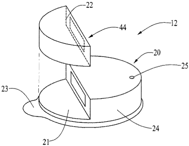
skin of a patient-user 1, in the manner of a patch, at a desired location on
the patient-user. In
such embodiments, it is desirable that the delivery device 12 have relatively
small dimensions
for comfort and ability to conceal the device, for example, under a garment.
[0090] Examples of patch-like delivery devices are described in U.S. Patent
Application No. 11/211,095, filed 8/23/05, which is incorporated herein, in
its entirety.
Delivery devices described in U.S. Patent Application No. 11/211,095 employ a
reservoir
structure having a moveable plunger for selectively driving fluid from the
reservoir. An
example of a patch-like delivery device 12 that employs a peristaltic pumping
arrangement,
instead of a reservoir-plunger arrangement is shown in Figs 2-5 herein. The
delivery device 12
in Fig. 2 includes a base housing portion 20 that, in some embodiments, may be
disposable
after one or a number of specified uses, and a further housing portion 22. For
convenience, but
without limitation, the base portion 20 is referred to herein as a disposable
housing portion or
disposable portion, while the further housing portion 22 is referred to herein
as a durable
housing portion or durable portion. However, as noted above, in operation,
either or both
housing portions 20 or 22 may be disposed of or re-used, depending upon the
context of use.
[0091] The disposable housing portion 20 may support structural elements that
ordinarily contact the patient-user's skin or the infusion medium, during
operation of the
delivery device 12. On the other hand, the durable housing portion 22 may
support elements
(including electronics, motor components, linkage components, and the like)
that do not
ordinarily contact the patient-user or the infusion medium during operation of
the delivery
device 12. Thus, elements in the durable housing portion 22 of the delivery
device 12 are
typically not contaminated from contact with the patient-user or the infusion
medium during
normal operation of the delivery device 12.
CA 02659199 2009-01-27
WO 2008/024812 PCT/US2007/076471
22
[0092] In the illustrated embodiment, the disposable housing portion 20 of the
delivery device 12 comprises a base 21 that includes or otherwise supports a
reservoir retaining
portion 24 that houses a reservoir. The durable housing portion 22 may
comprise a housing
that secures onto the base 21 adjacent the reservoir retaining portion 24. The
durable housing
portion 22 may house a suitable drive device, such as an electrically operated
motor (not shown
in Fig. 2), and drive linkage components (not shown in Fig. 2) for driving
fluid out of the
reservoir. The durable housing portion 22 also may house suitable control
electronics (not
shown in Fig. 2) for controlling the operation of the drive device to drive
fluid from the
reservoir in a controlled manner. Further embodiments may include other
electronics within
the durable housing portion 22, such as, but not limited to communication
electronics (not
shown in Fig. 2) for communicating with the sensor or monitor 14, the CCD 16,
the computer
18 and/or other components of the system 10 shown in Fig. 1.
[0093] The base 21 of the disposable housing portion 20 has a bottom surface
(facing
downward and into the page in Figs. 2 and 3) that is configured to secure to a
patient-user's
skin at a desired location on the patient-user. A suitable adhesive may be
employed at the
interface between the bottom surface of the base 21 and the patient-user's
skin, to adhere the
base 21 to the patient-user's skin. The adhesive may be provided on the bottom
surface of the
base 21, with a peelable cover layer 23 covering the adhesive material. In
this manner, a
patient-user may peel off the cover layer 23 to expose the adhesive material
and then place the
adhesive side of the base 21 against the patient-user's skin.
[0094] The disposable portion 20 may include a button or other operator 25 for
operating a needle inserter device located within the reservoir retaining
portion 24.
Alternatively, or in addition, reference number 25 may represent an opening,
through which an
external needle inserter device may operate. Alternatively, or in addition to
an operator or
opening 25, the needle inserter device may be activated, through a wireless
link, from an
external controller, such as the CCD 16, sensor or monitor 14 or computer 18.
For such
embodiments, the CCD 16, sensor or monitor 14 or computer 18 includes a
wireless signal
transmitter, while the delivery device includes a receiver for receiving a
wireless actuation
signal and an electronic actuator that is controlled to actuate the needle
inserter device, upon
receipt of an actuation signal from the CCD 16, sensor or monitor 14 or
computer 18.
CA 02659199 2009-01-27
WO 2008/024812 PCT/US2007/076471
23
Examples of suitable needle inserter devices are described in U.S. Patent
Application No.
11/211,095, filed 8/23/05, and U.S. Patent Application no. 60/839,840, filed
8/23/2006, titled
"Infusion Medium Delivery System, Device And Method With Needle Inserter And
Needle
Inserter Device Method" (attorney docket no. 047711- 0384), each of which is
incorporated
herein by reference in its entirety. Other needle/cannula insertion tools may
be used (or
modified for use) to insert a needle and/or cannula, such as for example U.S.
Patent Application
Serial No. 10/389,132 filed March 14, 2003, and entitled "Auto Insertion
Device For Silhouette
Or Similar Products," and/or U.S. Patent Application Serial No. 10/314,653
filed December 9,
2002, and entitled "Insertion Device For Insertion Set and Method of Using the
Same," both of
which are incorporated herein by reference in their entirety. Alternatively,
the reservoir
retaining portion may include a suitable opening or port for connecting one
end of a hollow
tube to the reservoir, while the other end of the hollow tube is connected to
a hollow needle for
piercing the patient-user's skin and conveying the infusion medium from the
reservoir into the
patient-user, for example, as described with reference to Fig. 2 of U.S.
Patent Application No.
11/211,095, filed 8/23/05.
[0095] The durable housing portion 22 of the delivery device 12 includes a
housing
shell configured to mate with and secure to the disposable housing portion 20.
The durable
housing portion 22 and disposable housing portion 20 may be provided with
correspondingly
shaped grooves, notches, tabs or other suitable features that allow the two
parts to easily snap
together, by manually pressing the two portions together in a manner well
known in the
mechanical arts. In a similar manner, the durable housing portion 22 and
disposable housing
portion 20 may be separated from each other by manually applying sufficient
force to unsnap
the two parts from each other. In further embodiments, a suitable seal, such
as an annular seal,
may be placed along the peripheral edge of the disposable housing portion 20
and/or the
durable housing portion 22, so as to provide a liquid, hermetic, or air-tight
seal between the
disposable housing portion 20 and the durable housing portion 22.
[0096] The durable housing portion 22 and disposable housing portion 20 may be
made of suitably rigid materials that maintain their shape, yet provide
sufficient flexibility and
resilience to effectively snap together and apart, as described above. The
base 21 material may
be selected for suitable compatibility with the patient-user's skin. For
example, the disposable
CA 02659199 2009-01-27
WO 2008/024812 PCT/US2007/076471
24
housing portion 20 and the durable housing portion 22 of the delivery device
12 may be made
of any suitable plastic, metal, composite material or the like. The disposable
housing portion
20 may be made of the same type of material or a different material relative
to the durable
housing portion 22. The disposable and durable housing portions may be
manufactured by
injection molding or other molding processes, machining processes or
combinations thereof.
[0097] The base 21 may be made of a relatively flexible material, such as a
flexible
silicone, plastic, rubber, synthetic rubber or the like. By forming the base
21 of a material
capable of flexing with the patient-user's skin, a greater level of patient-
user comfort may be
achieved when the base is secured to the patient-user's skin. Also, a flexible
base 21 can result
in an increase in the site options on the patient-user's body at which the
base 21 may be
secured.
[0098] The disposable housing portion 20 and/or the durable housing portion 22
may
include an internal sensor (not shown in Figs. 2 and 3) for connection to a
patient-user, for
example, through a needle (not shown in Figs 2 and 3) for piercing a patient-
user's skin when
the disposable housing portion 20 is secured to a patient-user's skin. In such
embodiments, a
suitable aperture (not shown in Figs. 2 and 3) may be formed in the base 21,
to allow the
passage of the sensor needle, when the sensor needle is extended to pierce a
patient-user's skin.
Alternatively, the durable housing portion 20 of the delivery device 12 may be
connected to an
external sensor 14, through a sensor lead, as described with respect to Fig. 2
of U.S. Patent
Application No. 11/211,095, filed 8/23/05. The sensor may comprise any
suitable biological
sensing device, depending upon the nature of the treatment to be administered
by the delivery
device 12. For example, in the context of delivering insulin to a diabetes
patient-user, the
sensor 14 may comprise a blood glucose sensor. Alternatively, or in addition,
one or more
environmental sensing devices may be included in or on the delivery device 12,
for sensing one
or more environmental conditions. In further alternatives, the sensor may be
included with as a
part or along side the infusion cannula and/or needle, such as for example as
shown in U.S.
Patent Serial No. 11/149,119 filed June 8, 2005, and entitled "Dual Insertion
Set," which is
incorporated herein by reference in its entirety.
CA 02659199 2009-01-27
WO 2008/024812 PCT/US2007/076471
[0099] As described above, by separating disposable elements of the delivery
device
12 from durable elements, the disposable elements may be arranged on the
disposable portion
20, while durable elements may be arranged within a separable durable portion
22. In this
regard, after one (or a prescribed number) of uses of the delivery device 12,
the disposable
portion 20 may be separated from the durable portion 22, so that the
disposable portion 20 may
be disposed of in a proper manner. The durable portion 22 may, then, be mated
with a new,
refurbished, user-filled, prefilled, refilled or re-manufactured disposable
portion 20 for further
delivery operation with a patient-user.
[0100] An example of a delivery device 12 having a disposable housing portion
20
and a durable housing portion 22 is shown in Fig. 4. In the embodiment of Fig.
4, a reservoir
26 is located in the reservoir retaining portion 24 of the disposable housing
portion 20. The
reservoir 26 may comprise a container having an internal volume for containing
a fluidic
infusion medium, such as, but not limited to an insulin formulation. The
reservoir 26 may be
made of any material suitably compatible with the infusion medium, including,
but not limited
to suitable metal, plastic, ceramic, glass, composite material or the like.
For example, the
canister may be formed of a plastic material referred to as TOPAS (trademark
of Ticona, a
subsidiary of Celanese Corporation), such as described in U.S. Patent
Application Serial No.
11/100,188, filed Apri15, 2005 (Publication No. 2005/0197626), the contents of
which is
incorporated herein in its entirety. Examples of needle/septum connectors used
in reservoirs
can be found in U.S. Patent Application Serial No. 10/328,393 filed December
22, 2003, and
entitled "Reservoir Connector," which is incorporated herein by reference in
its entirety. In
other alternatives, non-septum connectors for use with reservoirs such as Luer
locks, or the like
may be used.
[0101] The reservoir 26 may be supported by the reservoir retaining portion 24
of the
disposable portion 20 in any suitable manner. For example, the reservoir 26
may be supported
on a surface of the base 21 and held in place by one or more projections,
walls or other stop
surfaces 28. The projections, walls or other stop surfaces 28 may be formed or
molded on or
otherwise connected in a fixed manner to the base 21 or other structure of the
disposable
housing portion 20, in locations adjacent and abutting one or more sides of
the reservoir 26. As
described below, in some embodiments, the reservoir 26 may be configured to be
removable
CA 02659199 2009-01-27
WO 2008/024812 PCT/US2007/076471
26
and replaceable with respect to the disposable housing portion 20. In other
embodiments, the
reservoir 26 may be secured to the disposable housing portion 20 in a manner
intended to
inhibit removal of the reservoir 26 from the disposable housing portion 20.
For example, an
adhesive material may be employed to adhere a surface of the reservoir 26 to
the base 21 or
other structure of the disposable housing portion 20.
[0102] In yet other embodiments, the reservoir 26 may be formed unitarily with
the
reservoir retaining portion 24, for example, as a hollow chamber provided
within an otherwise
solid portion of the reservoir retaining portion 24. In such embodiments, the
hollow interior of
the reservoir retaining portion 24 may be coated or otherwise lined with a
suitable metal,
plastic, plastic, TOPAS (trademark of Ticona, a subsidiary of Celanese
Corporation), ceramic,
glass, composite material or the like. Alternatively, or in addition, the
retaining portion 24,
itself, may be made of a suitable metal, plastic, plastic, TOPAS (trademark of
Ticona, a
subsidiary of Celanese Corporation), ceramic, glass, composite material or the
like.
[0103] In the embodiment shown in Fig. 4, the reservoir 26 has a generally
rectangular-cube shape. In other embodiments, the reservoir 26 may have other
shapes,
including, but not limited to a disk or partial-disk shape, tube shape, curved
tube shape or other
shape that maximizes the internal volume of the reservoir, yet allows the
dimensions of the
reservoir retaining portion 24 to be minimized. As described below, in some
embodiments, the
reservoir 26 has a support surface 27 that may be formed as a flat surface
(Fig. 4) or a curved
surface (Fig. 6) for supporting a flexible tube against the action of a
peristaltic pump rotor.
[0104] The reservoir 26 has an outlet port 30, through which the infusion
medium
contained within the interior of the reservoir 26 may be communicated out of
the reservoir.
The outlet port 30 is open to the interior of the reservoir 26 and may include
suitable tube-
connection structure. A tube-shaped conduit 32 having an internal fluid flow
path is connected,
at a first end, in fluid-flow communication with the outlet port 30. The
conduit 32 may be
made of any suitable material, including, but not limited to silicone or other
plastic, metal,
ceramic or composite material. At least a portion 33 of the length of the
conduit 32 is made of
a resilient, flexible material, such as, but not limited to a silicone or
other plastic material
suitable for repeated contact with pads or rollers of a peristaltic rotor, as
described below, to
CA 02659199 2009-01-27
WO 2008/024812 PCT/US2007/076471
27
repeatedly compress and return the fluid flow path within the length portion
33 of the conduit
32. In some embodiments, the entire length of the conduit 32 is made of the
resilient, flexible
material.
[0105] A second end of the conduit 32 is connected in fluid flow communication
with
an injection site 35 located on the disposable housing portion 20. The
injection site 35 may
comprise an insertion mechanism to assist the insertion of a needle or cannula
into the patient-
user and connection of the needle or cannula in flow communication with the
conduit 32.
Examples of such insertion mechanisms that are built into a delivery device
are described in
U.S. Patent Application No. 11/211,095, filed 8/23/05, titled "Infusion Device
And Method
With Disposable Portion" (assigned to the assignee of the present invention),
which is
incorporated herein by reference in its entirety. Other needle/cannula
insertion tools may be
used (or modified for use) to insert a needle and/or cannula, such as for
example U.S. Patent
Application Serial No. 10/389,132 filed March 14, 2003, and entitled "Auto
Insertion Device
For Silhouette Or Similar Products," and/or U.S. Patent Application Serial No.
10/314,653 filed
December 9, 2002, and entitled "Insertion Device For Insertion Set and Method
of Using the
Same," both of which are incorporated herein by reference in their entirety.
[0106] In the embodiment shown in Fig. 4, the length portion 33 of the conduit
32 is
supported on a surface 27 of the reservoir 26, at a location arranged to be
contacted and
compressed by one or more pads or rollers of a peristaltic rotor, when the
durable housing
portion 22 is engaged with the disposable housing portion 20. The conduit
support surface 27
in Fig. 4 is a generally flat, outer surface of the reservoir 26. In other
embodiments, such as
shown in Fig. 6, the conduit support surface may comprise a curved surface,
for increased
length. While embodiments shown in Figs. 4 and 6 show the conduit support
surface 27 as an
outer surface of the reservoir 26, in other embodiments, the conduit support
surface may
comprise a flat or curved surface of a wall or other structural portion of the
disposable housing
portion 20.
[0107] A rotor 36 for a peristaltic pump arrangement is supported by the
durable
housing portion 22. In the embodiment of Fig. 4, the rotor 36 comprises first
and second
wheels 38 and 39, supported for rotation about their central axes. A belt,
ribbon, chain or
CA 02659199 2009-01-27
WO 2008/024812 PCT/US2007/076471
28
similar structure 40 extends in an annular path, around a portion of the outer
peripheral surface
of each of the wheels 38 and 39 and has extends along a generally flat path
for the length
between the wheels 38 and 39. In other embodiments, the belt 40 may extend in
an annular
path around more than two wheels 38 and 39. In the illustrated embodiment,
both wheels 38
and 39 are supported for rotation, while one of the wheels 38 is operatively
connected to a drive
device for driving the belt 40 around its annular path. In other embodiments,
only one wheel
(the drive whee138 that operatively connects to a drive device) may be
supported for rotation,
while the other whee139 may be non-rotating and provide a guide surface over
which the belt
40 may slide, as the belt is driven.
[0108] The belt 40 has at least one (preferably a plurality) of pads or
rollers 42
extending from the outer perimeter of the annular path of the belt. The pads
or rollers 42 may
comprise projections or nubs, rotatable wheel structures or the like on the
outer peripheral
surface of the belt. The wheels 38 and 39 are positioned on the durable
housing portion, such
that a generally flat length of the belt 40 extending between the wheels 38
and 39 is supported
adjacent the length 33 of the conduit 32 and in a proximity that allows the
pads or rollers 42 to
contact and compress conduit 32 along the length 33, when the durable housing
portion 22 is
engaged with the disposable housing portion 20 and the belt 40 is driven
around its annular
path.
[0109] The durable housing portion 22 has a side or wa1144 (Fig. 3) that faces
the
disposable housing portion 20, when the durable housing portion 22 is engaged
with the
disposable housing portion 20 as shown in Fig. 2. The side or wa1144 defines a
recess in which
the wheels 38 and 39 are located. The recess in the side or wa1144 is open on
the side facing
the disposable housing portion for the pads or rollers 42 of the belt 40 to
extend (and/or for a
portion of the belt to extend, depending upon the location of the wheels 38
and 39 relative to
the open side of the recess) for engaging the length 33 of the conduit 32,
when the durable
housing portion 22 is engaged with the disposable housing portion 20. The
disposable housing
portion 20 includes a side or wa1146 having an opening that faces the open
side of the recess in
the side or wa1144 of the durable housing portion 22, when the durable housing
portion 22 is
engaged with the disposable housing portion 20. The open side of the recess in
the side or wall
44 is arranged to align with the open side or wa1146, to expose the length 33
of the conduit 32
CA 02659199 2009-01-27
WO 2008/024812 PCT/US2007/076471
29
and allow the pads or rollers 42 of the belt 40 to engage the length 33 of the
conduit 32, when
the durable housing portion 22 is engaged with the disposable housing portion
20.
[0110] A drive device 47 is supported in the durable housing portion 22 and is
operatively connected to the drive whee138, to selectively rotate the drive
whee138 around its
central axis. The drive device 47 may comprise, for example, but not limited
to a motor or
other device for converting electrical power into rotational motion. Various
examples of drive
devices are described below. The drive device 47 may be operatively connected
to the drive
whee138, through any suitable gear, gear train, belt, shaft or other
arrangement. Examples of
suitable arrangements for operatively coupling an electronic motor to a
rotatable drive member
are described in U.S. Patent Application No. 11/211,095, filed 8/23/05, titled
"Infusion Device
And Method With Disposable Portion," which is incorporated herein by reference
in its
entirety.
[0111] The drive device 47 is connected to a control circuit 48 supported
within the
durable portion 22 of the delivery device, for controlling the operation of
the drive device
according to a desired infusion delivery program or profile. A delivery
program or profile may
be stored within a suitable electronic storage medium (not shown) located
within the durable
portion 22 and/or may be communicated to the delivery device 12 from other
sources, such as a
CCD 16 or a computer 18 (as shown in Fig. 1). In such embodiments, the
delivery program or
profile may be employed by the control circuit 48 to control the operation of
the drive device
47 in accordance with the delivery program or profile. Alternatively or in
addition, the control
circuit 48 may control the drive device 47 to deliver one or more discrete
volumes of the
infusion medium in response to delivery demand control signals generated
within the device 12
or communicated to the device 12 from other sources, such as a CCD 16 or a
computer 18 (as
shown in Fig. 1). Examples of the types of communications and/or control
capabilities, as well
as device feature sets and/or program options may be found in U.S. Patent
Application Serial
No. 10/445,477 filed May 27, 2003, and entitled "External Infusion Device with
Remote
Programming, Bolus Estimator and/or Vibration Alarm Capabilities," and U.S.
Patent
Application Serial No. 10/429,385 filed May 5, 2003, and entitled "Handheld
Personal Data
Assistant (PDA) with a Medical Device and Method of Using the Same," U.S.
Patent
Application Serial No. 09/813,660 filed March 21, 2001, and entitled "Control
Tabs For
CA 02659199 2009-01-27
WO 2008/024812 PCT/US2007/076471
Infusion Devices And Methods Of Using The Same," all of which are incorporated
herein by
reference in their entirety.
[0112] The durable portion 22 may contain additional electronic circuitry (not
shown)
for communication with external devices such as the CCD 16 or computer 18, for
storage of
sensor data or other data, for processing and control functions, or for other
functions. The
durable portion 22 may have a user interface (not shown) including one or more
buttons,
electronic display, or the like, and associated electronic interface circuitry
to allow a user to
access data and/or input data or instructions to control electronic circuitry
within the durable
portion 22.
[0113] The durable portion 22 may contain a battery, high energy capacitor or
other
electronic power source 50 for providing electrical power to the drive device
47, control circuit
48 and other electronic circuitry contained in the durable portion 22. In such
embodiments, the
battery, high energy capacitor or other electronic power source may be
rechargeable through a
recharge connector (not shown) provided on the durable portion 22.
Alternatively, or in
addition, the power source may be removable and replaceable with respect to
the durable
housing portion 22. In other embodiments, a battery, capacitor or other
electronic power
source (not shown) may be supported on the disposable portion 20 and
connectable to the drive
device 47, control circuit 48 and other electronic circuitry in the durable
housing portion,
through electrical connectors (not shown in Fig. 4) that make an electrical
connection upon the
durable portion 22 being coupled to the disposable portion 20, without
additional manual
manipulation. Such electrical connectors may include one or more pairs of
conductive pads,
where each pair of pads is connected to opposite poles of the power source and
located on any
suitable surface of the disposable portion 20 that engages a corresponding
surface on the
durable portion 22, when the durable portion 22 is engaged with the disposable
portion 20. In
such embodiments, the corresponding surface of the durable portion 22 includes
one or more
corresponding pairs of conductive pads that are electrically connected to the
drive device 47,
control circuit 48 and other electronic circuitry in the durable housing
portion and are arranged
to engage the conductive pads on the disposable portion, when the durable
portion 22 is
coupled to the disposable portion 20.
CA 02659199 2009-01-27
WO 2008/024812 PCT/US2007/076471
31
[0114] The durable portion 22 may include an interior volume 54 that contains
the
drive device 47, control circuit 48, other electronic circuitry described
above, gears or other
linkage to operatively couple the drive device 47 to the drive whee138 and, in
some
embodiments, a power source 50. To protect those electrical and mechanical
components from
certain environmental conditions (such as, but not limited to, moisture, air,
biological or
medical fluids), the interior volume 54 of the durable portion 22 may be
suitably sealed from
the external environment by the housing structure 55 that forms the durable
portion 22. In the
embodiment in Figs. 4 and 5, the wheels 38 and 39 and belt 40 may be supported
by the
durable portion 22, in a recess located outside of the interior volume 54. As
shown in Fig. 5, a
rotatable shaft 56 is axially connected to the drive whee138. The shaft 56 may
extend through
an aperture in a wall of the housing structure 55. One or more seals 58, such
as, but not limited
to, an o-ring seal may be arranged around the aperture. Accordingly, the
housing structure of
the durable portion 22 and the seal(s) 58 may form a suitable moisture-tight
seal, air-tight seal
and/or hermetic seal, to protect the electronic components located in the
interior volume 54
and/or separate those components from environmental, medical or biological
materials to which
the disposable portion 20 is exposed during normal operation.
[0115] A linkage structure for operably coupling the drive device 47 to the
shaft 56, to
transfer rotational motion to the shaft 56 may be included in the sealed
interior volume 54, to
protect and/or separate those mechanical components from environmental or
biological
materials, as well. In Fig. 5, the linkage structure 60 comprises at least two
engaged bevel
gears or other suitable structure arranged to communicate rotational motion
between a drive
shaft 62 of the drive device 47 and the shaft 56, where the axes of rotation
of the shafts 62 and
56 are non-parallel and may be orthogonal. Accordingly, as the drive device 47
is controlled to
selectively rotate the drive shaft 62, rotational motion of the drive shaft 62
is communicated
through the linkage structure 60 to provide rotational motion of the shaft 56
and, thus,
rotational motion of the drive whee138 to selectively drive the belt 40 around
its annular path.
[0116] As the belt 40 is driven around its annular path, the pads or rollers
42 engage
and press against the length 33 of the conduit 32, when the durable housing
portion 22 is
engaged with the disposable housing portion 20. As described above, the
spacing between the
first and second wheels 38 and 39 provides a generally straight or flat
portion of the annular
CA 02659199 2009-01-27
WO 2008/024812 PCT/US2007/076471
32
path of the belt adjacent the length 33 of the conduit 32. Accordingly, as the
belt 40 is
selectively driven around its annular path, the pads or rollers 42 on the belt
engage and slide or
roll along the length 33 of the conduit 32 for at least the distance between
the first and second
wheels 38 and 39. The reservoir 26 (or other structural in or of the
disposable housing portion)
provides a generally flat surface 27 for supporting the length 33 of the
conduit 32 against the
pressure applied by the pads or rollers 42 of the belt 40, to compress the
conduit 32 between
each pad or roller 42 and the generally flat surface, as the pad or roller 42
is moved along the
length 33 of the conduit 32.
[0117] Another rotor 36 and reservoir 26 configuration that may be used in a
delivery
device of Figs. 2-5 is shown in Fig. 6. The rotor 36 in Fig. 6 has a plurality
of pads or rollers
42 that are supported on a single rotary whee170. In Fig. 6, the whee170
comprises a structure
of spokes extending from a central hub, where each spoke has an end on which a
pad or roller
42 is disposed. The central hub of the whee170 may be coupled to a rotatable
shaft similar to
the rotatable shaft 56 that is coupled to the drive whee138 in Fig. 5.
Accordingly, the whee170
may be selectively driven by the drive device 47 in a manner similar to the
manner described
above for driving the drive whee138 in Fig. 5.
[0118] The whee170 in Fig. 6 is supported for rotation about a central axis 72
at a
location on the durable housing portion 22 at which the pads or rollers 42
will engage the
length 33 of the conduit 32, when the durable housing portion 22 is engaged
with the
disposable housing portion 20. In the embodiment of Fig. 6, the length 33 of
the conduit 32 is
supported on a concave-curved support surface 27 of the reservoir 26 (or other
structure in or of
the disposable housing portion 20). The concave curvature and location of the
support surface
27 in Fig. 6 may be selected to be about the same radius (or a slightly
greater radius) as the
radial distance of the outer surface of the pads or rollers 42 from the axis
72 of the rotary wheel
70, when the durable housing portion 22 is engaged with the disposable housing
portion 20. As
the rotary whee170 is selectively driven by the drive device 47, the pads or
rollers 42 are
moved around an annular, circumferential path and contact and slide or roll
along the curved
length 33 of the conduit 32. The pads or rollers compress the conduit 32
during their motion
along the curved length 33, to provide a peristaltic pumping action (a
pressure differential in
the conduit 32 across the rotor 36) sufficient to draw infusion fluid from the
reservoir 26,
CA 02659199 2009-01-27
WO 2008/024812 PCT/US2007/076471
33
through the conduit 32 and to the injection site 35. The curvature of the
support surface 27 in
Fig. 6 can help maximize the length 33 of the engageable portion of the
conduit 32, to improve
the peristaltic pumping action. The rotor 36 configuration of Fig. 6, thus,
does not require
multiple wheels and does not require a belt structure as described with
respect to Fig. 4. In yet
further embodiments, the rotor 36 of Fig. 4 or 6 may be supported on the
disposable housing
portion 20 and connectable to a rotary drive device supported on the durable
housing portion
22. Suitable structure for connecting a rotary drive device in one housing
portion to a rotor in
another housing portion is disclosed in U.S. Patent Application No.
11/211,095, filed 8/23/05,
titled "Infusion Device And Method With Disposable Portion," which is
incorporated herein by
reference in its entirety.
[0119] Another peristaltic drive configuration in a delivery device 112 is
shown in
Figs. 7-12. The embodiment in Figs. 7-12 may employ a two-part housing
structure, as
described above, including a disposable housing portion 120 and a durable
housing portion 122
that may function to engage and disengage similarly to the disposable and
durable housing
portions 20 and 22 described above. The two housing portions 120 and 122 are
shown in an
engaged orientation, in Fig. 7. The durable housing portion 122 is shown in a
top-down view
in Fig. 8 and in a side view in Fig. 9. The disposable portion 120 is shown in
a bottom-up view
in Fig. 10 and a side view in Fig. 11. Another side view of the two housing
portions 120 and
122 is shown in Fig. 12, with the disposable housing portion 120 oriented to
be engaged with
the durable housing portion 122, but located above and separated from the
durable housing
portion 122.
[0120] The disposable housing portion 120 supports a reservoir 126 having an
interior
volume for containing a fluidic infusion medium. The reservoir 126 may be
similar in structure
and function to the reservoir 26 described above.
[0121] The reservoir 126 has an outlet port 130, through which the infusion
medium
contained within the interior of the reservoir 126 may be communicated out of
the reservoir.
The outlet port 130 is open to the interior volume of the reservoir 126 and
may include suitable
tube-connection structure. A tube-shaped conduit 132 having an internal fluid
flow path is
connected, at a first end, in fluid-flow communication with the outlet port
130. The conduit
CA 02659199 2009-01-27
WO 2008/024812 PCT/US2007/076471
34
132 may be made of any suitable material, including, but not limited to
silicone or other plastic,
metal, ceramic or composite material. At least a portion 133 of the length of
the conduit 132 is
made of a resilient, flexible material, such as, but not limited to a silicone
or other plastic
material suitable for repeated contact with pads or rollers of a peristaltic
rotor, as described
below, to repeatedly compress and return the fluid flow path within the length
portion 133 of
the conduit 132. In some embodiments, the entire length of the conduit 132 is
made of the
resilient, flexible material.
[0122] A second end of the conduit 132 is connected in fluid flow
communication
with an injection site 135 located on the disposable housing portion 120. The
injection site 135
may be similar to the injection site 35 described above. For example, the
injection site 135
may include a needle inserter device for inserting a hollow needle or cannula
into a patient-
user's skin, when the delivery device 112 is secured to a patient-user's skin.
Examples of
needle inserter devices that may be used for moving a hollow needle or cannula
into a patient-
user and connecting the hollow needle or cannula in fluid flow communication
with a reservoir
are described in U.S. Patent Application No. 11/211,095, filed 8/23/05, and
U.S. Patent
Application No. 60/839,840, titled "Infusion Medium Delivery System, Device
And Method
With Needle Inserter And Needle Inserter Device Method", filed 8/23/2006,
(attorney docket
no. 047711-0384), each of which is incorporated herein by reference. Other
needle/cannula
insertion tools may be used (or modified for use) to insert a needle and/or
cannula, such as for
example U.S. Patent Application Serial No. 10/389,132 filed March 14, 2003,
and entitled
"Auto Insertion Device For Silhouette Or Similar Products," and/or U.S. Patent
Application
Serial No. 10/314,653 filed December 9, 2002, and entitled "Insertion Device
For Insertion Set
and Method of Using the Same," both of which are incorporated herein by
reference in their
entirety. In further embodiments, other suitable needle or cannula inserter
devices may be
employed. In yet further embodiments, a set of micro-needles may be employed,
instead f a
hollow needle or cannula.
[0123] In the embodiment shown in Figs. 8-12, the length portion 133 of the
conduit
132 is supported on a surface 127 of the disposable housing portion 120, at a
location arranged
to be contacted and compressed by one or more pads or rollers of a peristaltic
rotor, when the
durable housing portion 122 is engaged with the disposable housing portion
120. The length
CA 02659199 2009-01-27
WO 2008/024812 PCT/US2007/076471
portion 133 may extend in a circular path around at least a portion of the
circumference of a
circle (as shown in Fig. 10) having a radius about the same as the radius at
which one or more
wheels or pads of a rotor of a peristaltic pumping arrangement (described
below) are located.
As shown in Fig. 11, the conduit support surface 127 may be located within a
recessed portion,
such as an annular groove, provided on a side of the disposable housing
portion 120 that faces
and engages an opposite-facing side of the durable housing portion 122, when
the disposable
housing portion 120 and the durable housing portion 122 are engaged in the
manner shown in
Fig. 7. In such embodiments, the annular groove may have a radius and width
sufficient to
receive one or more wheels or pads of a rotor of a peristaltic pumping
arrangement (described
below). The location of the conduit 132 in an annular groove may help to avoid
damage to the
conduit during use, storage or shipping.
[0124] The durable housing portion supports a rotor 136 of a peristaltic
pumping
arrangement. The rotor 136 comprises a rotor wheel 137 that supports at least
one roller or pad
142, and preferably, a plurality of rollers or pads 1421ocated at spaced
intervals around the
perimeter of the rotor wheel 137. The rollers or pads 142 may comprise
rotatable wheels,
projections, nubs or the like. In embodiments in which the rollers or pads 142
are rotatable
wheels, each wheel is supported for rotation on a respective spoke of the
rotor wheel 137,
where the axis of rotation of each wheel is orthogonal to (and may be
perpendicular to) the axis
of rotation of the rotor wheel 137. That arrangement allows the rollers or
pads 142 to readily
align with and operatively engage the flexible portion 133 of the conduit 132,
when the durable
housing portion 122 is engaged with the disposable housing portion 120. In the
embodiment of
Fig. 8, the rotor 136 includes three rollers or pads 142. In other
embodiments, any suitable
number rollers or pads 142 may be employed. The rollers or pads 142 are
located at a radial
distance from the axis 147 of the rotor 136 that is about the same as the
radius of the circle
circumscribed by the flexible portion 133 of the conduit 132 and the radius of
the annular
groove for the support surface 127 on the disposable housing portion 120.
[0125] The rotor 136 is operatively coupled to a drive device 146, for
selective
rotation about the rotor axis 147 by the drive device 146. The drive device
146 is connected to
a control circuit 148 supported within the durable portion 122 of the delivery
device, for
controlling the operation of the drive device according to a desired infusion
delivery program
CA 02659199 2009-01-27
WO 2008/024812 PCT/US2007/076471
36
or profile. A delivery program or profile may be stored within a suitable
electronic storage
medium (not shown) located within the durable portion 122 and/or may be
communicated to
the delivery device 12 from other sources, such as a CCD 16 or a computer 18
(as shown in
Fig. 1). In such embodiments, the delivery program or profile may be employed
by the control
circuit 148 to control the operation of the drive device 146 in accordance
with the delivery
program or profile. Alternatively or in addition, the control circuit 148 may
control the drive
device 146 to deliver one or more discrete volumes of the infusion medium in
response to
delivery demand control signals generated within the device 12 or communicated
to the device
12 from other sources, such as a CCD 16 or a computer 18 (as shown in Fig. 1).
Examples of
the types of communications and/or control capabilities, as well as device
feature sets and/or
program options may be found in U.S. Patent Application Serial No. 10/445,477
filed May 27,
2003, and entitled "External Infusion Device with Remote Programming, Bolus
Estimator
and/or Vibration Alarm Capabilities," and U.S. Patent Application Serial No.
10/429,385 filed
May 5, 2003, and entitled "Handheld Personal Data Assistant (PDA) with a
Medical Device
and Method of Using the Same," U.S. Patent Application Serial No. 09/813,660
filed March
21, 2001, and entitled "Control Tabs For Infusion Devices And Methods Of Using
The Same,"
all of which are incorporated herein by reference in their entirety.
[0126] The durable portion 122 may contain additional electronic circuitry
(not
shown) for communication with external devices such as the CCD 16 or computer
18, for
storage of sensor data or other data, for processing and control functions, or
for other functions
as described above with respect to the circuitry in durable housing portion
22. The durable
portion 122 may have a user interface (not shown) including one or more
buttons, electronic
display, or the like, and electronic interface circuitry to allow a user to
access data and/or input
data or instructions to control electronic circuitry within the durable
portion 122.
[0127] The durable portion 122 may contain a battery, high energy capacitor or
other
electronic power source 150 for providing electrical power to the drive device
146, control
circuit 148 and other electronic circuitry contained in the durable portion
122. In such
embodiments, the battery, high energy capacitor or other electronic power
source may be
rechargeable through a recharge connector (not shown) provided on the durable
portion 122.
CA 02659199 2009-01-27
WO 2008/024812 PCT/US2007/076471
37
Alternatively, or in addition, the power source may be removable and
replaceable with respect
to the durable housing portion 122.
[0128] In other embodiments, such as shown in Fig. 13, a battery, capacitor or
other
electronic power source 150' may be supported on the disposable portion 120'.
More
specifically, in the embodiment of Fig. 13, a disposable housing portion 120'
and a durable
housing portion 122' function in a manner similar to the disposable housing
portion 120 and
durable housing portion 122 described above. However, in Fig. 13, the power
source 150' is
electrically connectable, through connectors 151' and 152', to a drive device
146', a control
circuit 148' and other electronic circuitry in the durable housing portion
122' (similar to the
drive device 146, control circuit 148 and other electronic circuitry in the
durable housing
portion 122 described above). The electrical connectors 151' and 152' may
comprise any
suitable structure that makes an electrical connection upon the durable
portion 122' being
coupled to the disposable portion 120', without additional manual
manipulation. However,
further embodiments may be configured in which additional manual manipulation
of the
disposable housing portion 120', the durable housing portion 122' and/or a
manual operator
(such as, but not limited to a button, lever or the like) may be required to
provide the electrical
connection, once the disposable housing portion 120' and the durable housing
portion 233' are
engaged.
[0129] In the embodiment shown in Fig. 13, the electrical connector 151'
comprises a
pair of electrical leads extending from the positive and negative poles of the
power source 150',
with a conductive pad on an exposed end of each lead. The electrical connector
152' comprises
a pair of electrical conductors connected to one or more of the control
circuit 148', the drive
device 146' and other electronic circuitry in the durable housing portion
122'. The
embodiment of Fig. 13 includes a reservoir 126', conduit 132' and a rotor 136'
(similar to the
reservoir 126, conduit 132 and rotor 136 described above).
[0130] In the embodiments of Figs. 8-13, the durable portion 122, 122' may
include
an interior volume 154, 154' that contains the drive device 146, 146' control
circuit 148, 148'
and other electronic circuitry as described above. In addition, the interior
volume 154, 154'
may contain gears or other linkage structure 160, 160' (similar to the linkage
structure 60
CA 02659199 2009-01-27
WO 2008/024812 PCT/US2007/076471
38
described above) to operatively couple the drive device 146, 146' to a
rotatable rotor shaft 156,
156'. To protect those electrical and mechanical components from certain
environmental
conditions (such as, but not limited to, moisture, air, biological or medical
fluids), the interior
volume 154, 154' of the durable portion 122, 122' may be suitably sealed from
the external
environment by the housing structure 155, 155' that forms the durable portion
122, 122'.
[0131] In the embodiments in Figs. 8-13, the rotor 136, 136' may be supported
by the
durable portion 122, 122', outside of the interior volume 154, 154'. The
rotatable shaft 156,
156' is axially connected to the rotor 136, 136'. The shaft 156, 156' may
extend through an
aperture in a wall of the housing structure 155, 155'. One or more seals 158,
158', such as, but
not limited to, an o-ring seal may be arranged around the aperture.
Accordingly, the housing
structure of the durable portion 122, 122' and the seal(s) 158, 158' may form
a suitable
moisture-tight seal, air-tight seal and/or hermetic seal, to protect the
electronic components
located in the interior volume 154, 154' and/or separate those components from
environmental,
medical or biological materials to which the disposable portion 120, 120' is
exposed during
normal operation.
[0132] Accordingly, as the drive device 146, 146' is controlled to selectively
rotate
the drive shaft 162, 162', rotational motion of the drive shaft 162, 162' is
communicated
through the linkage structure 160, 160' to provide rotational motion of the
shaft 156, 156' and,
thus, rotational motion of the rotor 136, 136' to selectively drive the
rollers or pads on the rotor
through an annular path.
[0133] As the rollers or pads on the rotor 136, 136' are driven in their
annular path,
the rollers or pads engage and compress the conduit 132, 132' during their
motion along the
annular path to provide a peristaltic pumping action (a pressure differential
in the conduit 132,
132' across the rotor 136, 136') sufficient to draw infusion fluid from the
reservoir 126, 126',
through the conduit 132, 132' and to the injection site 135, 135'.
[0134] In the embodiments of Figs. 4-13, a compression structure comprising at
least
one roller or pad of a rotor 136, 136' is arranged to engage and compress a
portion of the
conduit 132, 132' that extends from the infusion medium reservoir 126, 126'.
According to a
further embodiment, a compression structure, such as at least one roller or
pad, is arranged to
CA 02659199 2009-01-27
WO 2008/024812 PCT/US2007/076471
39
compress the infusion medium reservoir, itself. For example, an embodiment of
a delivery
device 212 as shown in Fig. 14 includes a disposable housing portion 220 and a
durable
housing portion 222, similar in structure and function to the disposable and
durable housing
portions 20 and 22, respectively, discussed above. The disposable housing
portion 220 and the
durable housing portion 222 are configured to be engaged, as shown in Fig. 14,
for operation,
yet be separable (as described above with respect to the disposable and
durable housing
portions 20 and 22).
[0135] The disposable housing portion 220 has an interior volume 224 that
contains a
reservoir 226. The reservoir 226 is arranged to abut against a rigid surface
227 within the
disposable housing portion 220. In the embodiment shown in Fig. 14, the
reservoir 226 abuts
against the inner surface 227 of the outer wall of the structure that forms
the disposable housing
portion 220. Also in the embodiment shown in Fig. 14, the inner surface 227 is
curved,
corresponding to the curvature of the outer wall of the structure that forms
the disposable
housing portion 220. In other embodiments, the rigid surface 227 against which
the reservoir
226 abuts may be a surface of another wall (not shown) of the disposable
housing portion 220
or the surface of another structure (not shown) located within the interior
volume 224 of the
disposable housing portion 220.
[0136] The reservoir 226 may comprise a flexible bag-like container, a tube-
like
structure or other container structure having at least one flexible wall for
receiving compression
pressure from a track roller, as described below. The reservoir 226 includes
an interior volume
for containing an infusion medium. In one example embodiment, the reservoir
226 comprises a
flexible bag-like container made of a flexible plastic, metal or composite
material, suitably
compatible with the infusion medium. A conduit having an internal fluid flow
path is coupled
in fluid flow communication with the interior of the reservoir 226 and an
injection site 235, for
providing a fluid flow path from the reservoir to the injection site. The
injection site 235 may
be similar to the injection site 35 or 135 described above.
[0137] The housing structure of the disposable housing portion 220 has a
wa11228
that faces an opposite-facing wa11229 of the durable housing portion 222, when
the disposable
housing portion 220 and the durable housing portion 222 are engaged as shown
in Fig. 14.
CA 02659199 2009-01-27
WO 2008/024812 PCT/US2007/076471
The wa11228 of the disposable housing portion 220 is provided with an opening
that aligns
with a corresponding opening of the wa11229 of the durable housing portion,
when the
disposable housing portion 220 and the durable housing portion 222 are engaged
as shown in
Fig. 14.
[0138] The durable housing portion has an interior volume 230 that contains a
movable track 232 (such as a rack of a rack and pinion arrangement), a drive
device 246, drive
control electronics 248, other electronics (not shown), a power source 250 and
linkage gears or
other linkage structure 260 for operatively coupling the drive device 246 to
the track 232, to
move the track 232 along an arched path. The drive device 246 may comprise a
drive device as
described above with respect to drive device 47. Similarly, the drive control
electronics 248,
other electronics (not shown) and power source 250 may comprise drive
electronics 48, other
electronics and a power source 50 as described above with respect to the
embodiment of Figs.
2-5.
[0139] In the embodiment of Fig. 14, the track 232 is curved to correspond
(approximate) the curvature of the inner surface 227 in the disposable housing
portion 220.
The track 232 is supported to move in an arched path 252 that extends along
the direction of
curvature of the track 232. The track 232 has a surface provided with
serrations or teeth
configured for engaging corresponding serrations or teeth on an engagement
gear 262 (such as
a pinion gear of a rack and pinion arrangement) of the linkage 260. The
engagement gear 262
is operatively coupled through the rest of the linkage 260 to be selectively,
rotatably driven by
the drive device 246, for example, but not limited to the linkage 60 that
operatively couples the
drive device 47 to selectively, rotatably drive the whee138 described above.
In the
embodiment of Fig. 14, the track 232 is provided with serrations or teeth the
curved surface of
the track that forms a concave shape. However, in other embodiments, the track
232 may be
provided with serrations or teeth along its convex curved side or on the
surface facing out of
the page or the surface facing into the page (relative to the orientation
shown in Fig. 14), for
engaging an engagement gear 262 suitably located adjacent the serrated or
toothed surface of
the track 232.
CA 02659199 2009-01-27
WO 2008/024812 PCT/US2007/076471
41
[0140] The track 232 is configured to extend through the aperture in the
wa11229 of
the durable housing portion 222, such that a portion of the curved length of
the track 232 is
located inside of the internal volume of the durable housing portion 222 and a
further portion of
the curved length of the track 232 extends out of the aperture in the wa11229.
When the
disposable housing portion 220 and the durable housing portion 222 are
engaged, as shown in
Fig. 14, the portion of the track 232 that extends out of the aperture in the
wa11229 of the
durable housing portion 222 is arranged to extend into the aperture in the
wa11228 of the
disposable housing portion 220.
[0141] The track 232 may be supported for movement along the arcuate path 252
by a
combination of the engagement gear 262 and one or more of a further gear (not
shown)
engaging the convex side of the curved track 232 or one or more support
rollers or pads 264
connected to the track 232 and arranged to slide or roll along a curved
surface such as the
interior surface of the structure that forms the outer wall of the durable
housing portion 222.
Alternatively, or in addition, such support rollers or pads 264 may be
arranged to roll along
another curved surface of or within the durable housing portion 222.
Alternatively, or in
addition, the track 232 may be guided within one or more grooves, channels or
other guide
structures (not shown) formed on one or both of the durable housing portion
222 and
disposable housing portion 220, for engaging the track 232 and maintaining the
track 232 along
the arcuate path 252.
[0142] A compression mechanism comprising at least one compression pad or
roller
266 is supported on the portion of the track 232 that extends into the
interior of the disposable
housing portion, when the disposable housing portion 220 and the durable
housing portion 222
are engaged as shown in Fig. 14. The compression pad(s) or roller(s) 266 may
be arranged to
impart a compression force on a flexible wall of the reservoir 226, when the
disposable housing
portion 220 and the durable housing portion 222 are engaged as shown in Fig.
14.
[0143] In particular, the compression pad(s) or roller(s) 266 may engage a
flexible
wall of the reservoir 226 and impart a compression force directed toward the
surface 227
against which the reservoir 226 is abutted. The compression force imparted by
the
compression pad(s) or roller(s) 266 is sufficient to compress the portion of
the reservoir 226
CA 02659199 2009-01-27
WO 2008/024812 PCT/US2007/076471
42
that is located between the compression pad(s) or roller(s) 266 and the
surface 227. The width
dimension (in the direction into and out of the page in the orientation shown
in Fig. 14) of the
compression pad(s) or roller(s) 266 is at least as great as the width
dimension (in the direction
into and out of the page in the orientation shown in Fig. 14) of the reservoir
226. The
compression pad(s) or roller(s) 266 are arranged to slide or roll along the
reservoir 266 and
compress the reservoir, as the track 232 is moved in the arcuate path 252, in
the direction of
arrow 272. Accordingly, as the compression pad(s) or roller(s) 266 compress a
portion 270 of
the reservoir 226, as shown in Fig. 14, the internal volume of an infusion-
medium-containing
portion 271 of the reservoir 226 reduces and the pressure within the infusion-
medium-
containing portion of the reservoir 226 increases to cause infusion medium to
be forced out of
the reservoir 226, toward the injection site 235.
[0144] While the compression pad(s) or roller(s) 266 in Fig. 14 are coupled to
the
moveable track 232, in other embodiments, one or more compression pad(s) or
rotatable
roller(s) may be supported in a fixed relation (with roller axis in a fixed
location) relative to the
disposable housing portion 220, while the reservoir may be coupled to the
moveable track. For
example, Fig. 15 shows an embodiment in which a pair of compression pads or
rollers 266' are
arranged adjacent each other and secured to the disposable housing portion 220
in a fixed
location (although they may be rotatable) with respect to the disposable
housing portion 220.
The width dimension (in the direction into and out of the page in the
orientation shown in Fig.
15) of the compression pads or rollers 266' is at least as great as the width
dimension (in the
direction into and out of the page in the orientation shown in Fig. 15) of the
reservoir 226'.
[0145] The embodiment of Fig. 15 includes a reservoir 226' and a moveable
track
232', which may be similar to the reservoir 226 and track 232 described above
with respect to
Fig. 14. However, in Fig. 15, the reservoir 226' is secured to the portion of
the track 232' that
extends into the disposable housing portion, when the disposable housing
portion 220' and the
durable housing portion 222' are engaged (in a manner similar to that shown in
Fig. 14). Also,
in the embodiment of Fig. 15, the drive device and linkage (246 and 260 in
Fig. 14) are
configured to selectively move the track 232' in the direction of arrow 272'
(opposite to the
direction of arrow 272 in Fig. 14), to selectively pull a portion of the
reservoir 226' through a
space between the compression pads or rollers 266'.
CA 02659199 2009-01-27
WO 2008/024812 PCT/US2007/076471
43
[0146] The spacing between the compression pads or rollers 266' is selected to
allow
the compression pads or rollers 266' to compress the portion of the reservoir
226' located
between the pads or rollers, to substantially deplete infusion medium from
that portion of the
reservoir and reduce the infusion-medium-containing portion of the reservoir
226', as the
reservoir is pulled through the space between the compression pads or rollers
266' by
movement of the track 232' in the direction of arrow 272'. Accordingly, as the
reservoir 226'
is compressed by the compression pad(s) or roller(s) 266', the internal volume
of an infusion-
medium-containing portion 271' of the reservoir 226' reduces and the pressure
within the
infusion-medium-containing portion of the reservoir 226' increases to cause
infusion medium
to be forced out of the reservoir 226', toward the injection site 235'. The
reservoir 226' and
moveable track 232' of Fig. 15 may be used in place of the reservoir 226 and
moveable track
232 of Fig. 14.
[0147] In further embodiments, a reservoir 226' may extend between (and be
compressed by) a pair of compression rollers or pads 266' similar to the
arrangement shown in
Fig. 15. However, in further embodiments, the compression pads or rollers 266'
comprise at
least one (and, preferably, two) rotatable roller members, and where one or
both of the roller
members is (are) operatively coupled to a drive device for rotation of the
roller member(s). By
rotatably driving the roller member(s) 266' with a drive device, the depleted
portion 271' of the
reservoir 226' may be driven through the space between the roller member(s)
266', to further
reduce the internal volume of an infusion-medium-containing portion 271' of
the reservoir 226'
and, thus, increase the pressure within the infusion-medium-containing portion
of the reservoir
226' to cause infusion medium to be forced out of the reservoir 226', toward
the injection site
235'. Also, while embodiments shown in Figs. 14 and 15 employ a track 232
having a curved
shape, to accommodate the circular shape of the interior of the disposable
housing portion 220
and minimize space usage, other embodiments may employ a track 232 having a
generally
straight length along its serrated or toothed side.
[0148] A further embodiment of a delivery device 212" in Figs. 16 and 17 is
similar
in various structural and functional features as the delivery device 212
described above, in that
the delivery device 212" includes a disposable housing portion 220" and a
durable housing
portion 222" (similar to the disposable housing portion 220 or 220' and
durable housing
CA 02659199 2009-01-27
WO 2008/024812 PCT/US2007/076471
44
portion 222 or 222' described above). In Figs. 16 and 17, a track 232"
(similar to the track 232
or 232' discussed above) operates with a plunger head 280 attached to or
engaged with the end
of the track portion that extends into the disposable housing portion 220".
The track 232"
may be operatively coupled to a drive device 246", through suitable linkage
structure 260", as
described above with respect to the track 232, drive device 246 and linkage
structure 260 in
Fig. 14.
[0149] A reservoir 226" is located in the disposable housing portion 220" and
has an
interior volume for containing an infusion medium. The reservoir 226" may
comprise a rigid,
tubular structure or channel having a curved interior volume, where the curved
interior volume
extends along a curved longitudinal direction and has a radius of curvature
about the same as
the radius of curvature of the track 232". The interior volume of the
reservoir 226" may be
connected to an injection site 235". For example, the reservoir 226" may
comprise structure
and functionality similar to the reservoirs described in co-pending U.S.
Patent Application
Serial No. 60/839,822, filed 8/23/2006, titled "Infusion Medium Delivery
Device And Method
For Driving Plunger In Reservoir" (attorney docket no. 047711-0382), but
having a curved
interior volume. In one embodiment, a plunger head 280 may be disposed within
the reservoir,
such that one end of the track 232" is arranged to abut (engage) the plunger
head 280, when
the durable housing portion 222" is engaged with the disposable housing
portion 220", as
shown in Fig. 16, yet separate (disengage) from the plunger head 280 when the
durable housing
portion 222" is separated from the disposable housing portion 220". In another
embodiment,
the plunger head 280 may be fixed to one end of the track 232" and may be
inserted into the
reservoir 226", when the durable housing portion 222" is engaged with the
disposable housing
portion 220", as shown in Fig. 16, and may be withdrawn from the reservoir
226" when the
durable housing portion 222" is separated from the disposable housing portion
220".
[0150] In the embodiment shown in Fig. 16, the reservoir 226" comprises a
curved
tubular structure having a curved central axis 282 extending in the
longitudinal direction of the
tubular structure. The curved tubular structure of the reservoir 226" in Fig.
16 has an outer
radius of curvature approximately equal to the radius of curvature of the
inner wall surface
227" of the disposable housing portion 220". The curvature of the reservoir
226", thus, may
be selected to help maximize the efficient use of the interior volume 224" of
the disposable
CA 02659199 2009-01-27
WO 2008/024812 PCT/US2007/076471
housing portion 220", by minimizing unused, open space within the interior
volume 224"
without reducing the interior volume of the reservoir. Accordingly, a curved
reservoir may be
employed to help minimize certain dimensions of the delivery device 12",
without reducing the
reservoir capacity.
[0151] The plunger head 280 in Figs. 16 and 17 has a suitable shape and
dimension to
be moveable within the interior volume of the reservoir 226". The plunger head
280 may
include one or more seals 284, such as, but not limited to o-ring seals, to
provide a fluid seal
between the outer peripheral surface of the plunger head and the inner surface
of the reservoir
226". When engaged with the end of the track 232", the plunger head 280 is
moveable in the
direction of arrow 286, upon the track 232" being driven by the drive device
246" in the
direction of arrow 286. As the plunger head 280 is moved within the reservoir
226" in the
direction of arrow 284, the infusion-medium-containing volume of the reservoir
226" is
reduced and the pressure within the infusion-medium-containing portion of the
reservoir 226"
is correspondingly increased, to cause infusion medium to be forced out of the
reservoir 226",
toward the injection site 235".
[0152] A delivery device 312 according to a further embodiment of the present
invention includes a reservoir having a generally disk-like shape with a
circular or elliptical
cross-section, or other smooth cross-sectional shape, to accommodate sealing
between a
reservoir plunger and the inner surface of the reservoir. In the embodiment of
Fig. 18, a
disposable housing portion 320 comprises a reservoir 326 that has an enclosed
interior volume
with a generally circular cross-sectional shape (forming a partial circle),
such that the inner
wall surface of the reservoir has a radius of curvature that forms at least a
partial circle. The
disposable housing portion 320 may be formed of any suitable material, such as
described
above with respect to the disposable housing portion 20.
[0153] In Fig. 18, the inner wall surface 327 of the reservoir 326 is (or has
the same
shape and similar dimension as) the outer peripheral wall of the reservoir
326. Accordingly,
the volume of the reservoir 326 may be maximized for a given outer dimension
of the
disposable housing portion 320.
CA 02659199 2009-01-27
WO 2008/024812 PCT/US2007/076471
46
[0154] A plunger in the form of a rotor arm 336 is supported for rotation
within the
reservoir 326. In Fig. 18, the rotor arm 336 is supported at one end on a
rotation axis 338,
about which the arm 336 may rotate in the direction of arrow 340. The rotor
arm 336 has a
width dimension (extending into and out of the page, in the orientation shown
in Fig. 18) about
as great as the width dimension (into and out of the page, in the orientation
shown in Fig. 18) of
the reservoir 326, such that the rotor arm spans the full width (into and out
of the page, in the
orientation shown in Fig. 18) of the reservoir 326. The rotor arm 336 may be
made of any
suitably rigid material, including, but not limited to a metal, plastic,
ceramic or composite
material, or combinations thereof.
[0155] In the embodiment of Fig. 18, the rotor arm axis 338 is coaxial with
the axis of
the circular shape of the inner wall surface of the reservoir (which may be
the same surface as,
or coaxial with, the inner wall surface 327 of the disposable housing portion
320). The arm
336 extends from the rotation axis 338, radially outward a distance about
equal to (or slightly
less than) the radius of the inner wall surface of the reservoir 326, toward
the inner wall surface
of the reservoir. One or more seals 342 may be secured to the second end of
the arm 336, to
provide a fluid seal between the inner wall surface of the reservoir and the
arm 336. One or
more seals (not shown) may be provided on the surfaces of the arm 336 facing
into and out of
the page in the orientation shown in Fig. 18, to provide a fluid seal between
the arm 336 and
the bottom and top surfaces of the reservoir 326 (with respect to the
orientation shown in Fig.
18). One or more air passages 343 may be provided between the interior of the
reservoir 326
and an external environment, to equalize pressure within the reservoir 326, as
the infusion
medium is driven out of the reservoir or filled or re-filled into the
reservoir. The air passages
may be covered with an air-permeable material that inhibits the passage of
infusion media, but
allows the passage of air. Examples of structures that permit air-flow, but
that inhibit fluids can
be found in U.S. Patent Application Serial No. 10/328,393 filed December 22,
2003, and
entitled "Reservoir Connector," and U.S. Patent Application Serial No.
10/699,429 filed
October 31, 2003, and entitled "External Infusion Device with a Vented
Housing," both of
which are incorporated herein by reference in their entirety.
[0156] An outlet 341 is provided in fluid flow communication with the interior
volume of the reservoir 326 and couples to a conduit 339 that is in fluid flow
communication
CA 02659199 2009-01-27
WO 2008/024812 PCT/US2007/076471
47
with an injection site 335. The injection site 335 may be similar to the
injection site 35, 135
and 235 described above. As the arm 336 is selectively driven in the direction
of arrow 340,
the pressure of the infusion medium within the interior of the reservoir 326
increases and the
infusion medium is forced out of the outlet 341 and through the conduit 339 to
the injection site
335. In the embodiment shown in Fig. 18, the conduit 339 extends out from the
disposable
housing portion, to an injection site 335 that is external to the disposable
housing portion. In
further embodiments, the injection site 335 may be located within the
disposable housing
portion, for example, as shown in broken lines at 335' in Fig. 18.
[0157] A durable housing portion 322 shown in Fig. 19 is configured to engage
and
operatively couple to the disposable housing portion 320 in Fig. 18. The
durable housing
portion 322 may include an enclosed interior volume that contains a drive
device, drive control
electronics, other electronics, a power source and linkage structure, as
described above with
respect to the durable housing portion 22 of Fig. 4.
[0158] In the embodiment of Fig. 19, the drive device within the durable
housing
portion is operatively coupled, through suitable linkage structure as
described above, to
rotatably drive a rotatable shaft 344. The rotatable shaft 344 is supported
for rotation by the
durable housing portion 322 and extends through an aperture in a wall of the
durable housing
portion 322. One or more seals, such as, but not limited to o-ring seals, may
be disposed
around the aperture in the durable housing portion wall through which the
shaft 344 extends.
[0159] The end of the shaft 344 that extends outside of the durable housing
portion
322 may include a mating connector, for engaging and operatively mating with a
corresponding
mating connector coupled to the rotor arm 336. For example, the shaft 344 may
have a non-
circular cross-section (cross-section in the plane perpendicular to the
longitudinal axis of the
shaft 344) that mates with an axial-directed aperture 335 in the arm 336. The
aperture 335 has
a non-circular cross-section shape that corresponds to the cross-section shape
of the shaft 344
to allow the shaft 344 to be inserted into the aperture 335 and to rotate the
arm 336 with
rotation of the shaft 344. In the embodiment of Figs. 18 and 19, the non-
circular cross-
sectional shape of the shaft 344 and the aperture 335 is generally a "D"
shape. However, other
CA 02659199 2009-01-27
WO 2008/024812 PCT/US2007/076471
48
embodiments may employ other suitable, non-circular shapes, including, but not
limited to,
oval, elliptical, polygonal, star, cross shapes or the like.
[0160] Accordingly, in the embodiment of Figs. 18 and 19, the drive device
within the
durable housing portion is operatively coupled, through suitable linkage
structure, to rotatably
drive a rotatable shaft 344. Fig. 20 shows another embodiment in which a
similar drive device
within a similar durable housing portion may be operatively coupled, through
suitable linkage
structure, to rotatably drive a rotary shaft to selectively drive fluid from a
reservoir.
[0161] The structure in Fig. 20 includes a rotor 502 supported for rotation
relative to a
housing 504, about an axis A5. The housing 504 may be located within the
disposable housing
portion 20 and/or may be a section of the disposable housing portion 20
described above with
respect to Figs. 2 and 3. The housing 504 may be selectively engaged with and
disengaged
from a durable housing portion that contains a drive device, as described
above with respect to
the drive device 47.
[0162] In the embodiment of Fig. 20, the housing 504 has a base portion 504a
and a
cover portion 504b. The base portion 504a and cover portion 504b may be
separate elements
that are connected together or may be formed as a unitary structure. In
embodiments in which
the base portion 504a and cover portion 504b are separate elements that are
connected together,
one or more seals, such as, but not limited to, o-ring or annular, flat gasket
seals, may be
provided between the base portion 504a and the cover portion 504b, to inhibit
leakage of fluid
(such as an infusion medium) between those elements, when they are connected
together.
[0163] First and second channels 506 and 508 extend through the base portion
504a of
the housing 504, in a spaced relation relative to each other and to the axis
A5 of the rotor 502.
In the embodiment of Fig. 20, the channels 506 and 508 are located at 180
degrees around the
axis A5, relative to each other. However, in other embodiments, the channels
may be located at
other suitable spacing around the axis A5, relative to each other.
[0164] The first and second channels 506 and 508 in the base portion 504a of
the
housing 504 form fluid inlet and outlet channels, respectively, as described
below. The cover
portion 504b of the housing 504 has an interior volume and a cam surface 528
that includes a
CA 02659199 2009-01-27
WO 2008/024812 PCT/US2007/076471
49
cam lobe 528b for contacting cams, a non-camming surface portion 528a that
does not move
the cams and a ramp portion 528c connecting the non-camming surface with the
cam lobe.
One end of each of the first and second channels 506 and 508 is open to the
interior volume of
the housing 504.
[0165] The rotor includes a shaft 510 that extends through a channe1512 in the
base
portion 504a and through an opening 514 in the cover portion 504b of the
housing 504. The
rotor shaft 510 has one end segment 510a that extends through the opening 514
and out of the
housing 504 and is arranged for operable connection with a drive device,
either directly or
through suitable linkage structure, for example, as described above with
respect to the
connection of the rotary shaft 344 with the drive device arm 336, when the
disposable housing
portion 20 and the durable housing portion 22 are engaged. For example, the
rotor shaft 510
may include a non-circular cross-sectional shape that mates with a
correspondingly shaped
aperture in an end of a rotatable shaft that is operatively connected to the
drive device (similar
to the non-circular, cross-section shaped mating elements of the shaft 344 and
aperture 335 in
Figs. 18 and 19. In Fig. 20, The rotor shaft has a second end segment 5 1 Ob
that extends
through the channe1512 in the base portion 504a and out of the housing 504.
The rotor also
includes a disk-shaped body 510c, located between the two end segments 5 l0a
and 5 1 Ob. The
end segments 510a and 5 1 Ob and the disk-shaped body 510c of the rotor 510
may be formed as
multiple separate elements connected together, or may be formed as a single,
unitary structure
in the configuration shown in Fig. 20.
[0166] The rotor body 510c is located within the interior volume of the cover
portion
504a of the housing 504. The rotor body 510 includes at least two cam-follower
channels 516
and 518, located in a spaced relation relative to each other and to the axis
AS of the rotor 502,
corresponding to the spaced relation of the first and second channels 506 and
508 in the base
portion 504a of the housing 504. The corresponding spaced relation allows the
two cam-
follower channels 516 and 518 in the rotor body 510c of the rotor 510 to
simultaneously align
with the first and second channels 506 and 508 in the base portion 504a of the
housing 504. In
the embodiment of Fig. 20, the cam follower channels 516 and 518 are located
at 180 degrees
around the axis A5, relative to each other. However, in other embodiments, the
cam follower
channels 516 and 518 may be located at other suitable spacing around the axis
A5, relative to
CA 02659199 2009-01-27
WO 2008/024812 PCT/US2007/076471
each other. Also, while the embodiment in Figs. 20-23 includes two cam
follower channels and
two associated cam followers, other embodiments may include no more than one
cam follower
channel and associated cam follower or more than two cam follower channels and
associated
cam followers.
[0167] A cam follower 520 is located in the cam follower channe1516 and a
second
cam follower 522 is located in the cam follower channe1518. The cam followers
520 and 522
are moveable within their respective cam follower channels 516 and 518, in the
directions of
arrows 524 and 525. In the illustrated embodiment, the cam follower channels
516 and 518 and
the cam followers 520 and 522 are arranged such that the directions of
movement 524 and 525
of the cam followers 520 and 522 are substantially parallel to the axis A5 of
the rotor 510.
However, in other embodiments, the channels 516 and 518 and cam followers 520
and 522 may
be arranged for movement in a direction transverse to the axis A5 of the rotor
510.
[0168] The cam followers 520 and 522 may be made of any suitably rigid
material,
including, but not limited to, metal, plastic, ceramic, composite material or
the like. The cam
followers 520 and 522 have a shape that allows them to fit within the
respective cam follower
channels 516 and 518 and move in the directions of arrows 524 and 525,
relative to the body
510c of the rotor 510. Each cam follower 520 and 522 includes a head portion
520a and 522a,
respectively, on one end that is external to rotor body 510c. The head
portions 520a and 522a
have a size or shape that inhibits the head portions from passing through the
respective cam
follower channe1516 or 518. The cam followers 520 and 522 each have a length
in the axial
dimension A5 sufficient to allow an end portion of each cam follower 520 and
522 opposite to
the head portions 520a and 522a, to extend a distance out of the channels 516
and 518, when
the respective cam follower 520 and 522 is moved to its full extent of motion
in the direction of
arrow 524.
[0169] A suitable bias member 526 may be associated with each cam follower 520
and 522 to urge the cam followers 520 and 522 in the direction of arrow 525,
toward a cam
surface 528 in the cover portion 504b of the housing 504. In the embodiment of
Fig. 20, the
bias members 526 each comprise a spring, such as, but not limited to a coil
spring, bevel
spring, or the like, located between the rotor body 5 10c and a respective
head portion 520a or
CA 02659199 2009-01-27
WO 2008/024812 PCT/US2007/076471
51
522a of each cam follower 520 and 522. In other embodiments, the bias members
526 may
comprise one or more magnets arranged to impart a magnetic force on a magnetic
material of
or within each cam follower 520 and 522.
[0170] In the embodiment of Fig. 20, the cam surface 528 comprises an interior-
facing surface, having poritions 528a, 528b and 528c, discussed above, that
surrounds the
opening 514 in the cover portion 504b of the housing 504. The cam surface 528
extends
around the circumference of the axis A5 of the rotor 510 and has a first
portion 528a aligned
with the inlet channe1506 and a second portion 528b aligned with the outlet
channe1508. The
second portion 528b of the cam surface 528 is arranged closer to the rotor
body 510c than the
first portion 528a of the cam surface 528. For example, the second portion
528b of the cam
surface 528 may be provided on a wide or thick wall segment of the cover
portion 504b of the
housing 504, relative to the wall width or thickness of the cover portion 504b
at the first portion
528a of the cam surface 528. The cam surface 528 may be a smooth, continuous
surface that
extends from the first portion 528a to the second portion 528b and back to the
first portion
528a, around the axis A5.
[0171] A flexible membrane 530 is located adjacent the surface of the rotor
body 510c
that faces the base portion 504a of the housing 504. The flexible membrane 530
may comprise
a disk-shaped sheet of flexible material, such as, but not limited to a
silicone, rubber or other
suitable material, secured to one surface (the surface facing the base portion
504a of the
housing 504) of the rotor body 510c.
[0172] A sealing member 532 is secured to the flexible membrane 520 and rotor
body
510c and is located between the flexible membrane 530 on the rotor body 510c
and the base
portion 504a of the housing 504. The sealing member 532 may be a disc-shaped
plate of
material that provides a suitable fluid seal and that allows rotational motion
of the rotor body
510c, relative to the sealing member 530. The sealing member 532 maybe made of
polytetrafluoroethylene or other suitable material that provides a relatively
low friction surface
facing the base portion 504a of the housing 504. The sealing member 532
includes a first
passage 532a arranged in alignment with one of the cam follower channels
(channe1516 in Fig.
20). The sealing member 532 also includes a second passage 532b arranged in
alignment with
CA 02659199 2009-01-27
WO 2008/024812 PCT/US2007/076471
52
the other cam follower channel (channe1518 in Fig. 20). In embodiments in
which the rotor
body 510c includes more or less than two cam follower channels, the sealing
member 532
includes a corresponding number of passages (e.g. passages 532a and 532b).
[0173] A clamp structure may be provided to provide a clamping force, for
clamping
the sealing member 532 between the flexible membrane 530 on rotor body 510c
and the base
portion 504a of the housing 504. In the embodiment of Fig. 20, the clamping
structure
comprises a plate 534 attached by a screw to the free end of the end segment 5
1 Ob of the rotor
shaft 510 (or otherwise secured to the end segment 5 1 Ob of the rotor shaft
510) and a coil
spring 536 arranged between the plate 534 and the base portion 504a of the
housing 504. The
coil spring 536 is provided with a suitable tension to urge the rotor in the
direction of arrow
524, relative to the housing 504.
[0174] In operation, the rotor 502 is arranged such that the end segment 510a
of the
rotor shaft 510 is operatively engaged with a drive device located in a
durable housing portion
22 (either directly, or through a suitable linkage structure), when the
disposable housing portion
20 is engaged with the durable housing portion 22, as described above. When
operatively
engaged with the drive device, the rotor 502 (and the attached membrane 530
and sealing
member 532) may be selectively rotated around the axis AS of the rotor 510, by
selective
activation of the drive device.
[0175] As the rotor 502 rotates, the cam followers 520 and 522 are moved along
the
cam surface 528. The bias members 526 urge the heads 520a and 522a of the
respective cam
followers 520 and 522 against the cam surface 528. When the rotor 502 is
rotated to a position
at which a cam follower is aligned with the inlet channe1506 (such as the cam
follower 520 in
Figs. 20 and 21), the head of that cam follower (such as the head 520a of cam
follower 520 in
Figs. 20 and 21) abuts against the first portion 528a of the cam surface 528.
The first portion
528a of the cam surface 528 and the length of the cam followers 520 and 522
are selected to
allow the end of the cam follower that faces the base portion 504a of the
housing 504 to be
separated from the base portion 504a by a distance sufficient to form an open
volume 540 in
the passage 532a of the sealing member 532, between the flexible membrane 530
and the base
CA 02659199 2009-01-27
WO 2008/024812 PCT/US2007/076471
53
portion 504a of the housing 504, when the head of the cam follower abuts the
first portion 528a
of the cam surface 528.
[0176] Rotary motion of the rotor 502 causes the cam followers 520 and 522 to
move
along the cam surface 528 and, as a result, to move in the direction of arrow
525 as the cam
follower moves from the second portion 528b, to the first portion 528a of the
cam surface 528.
As the cam follower (520 in Figs. 20 and 21) is moved in the direction of
arrow 525, a portion
of the flexible membrane 530 that defines one side of the chamber 532a flexes
away from the
base portion 504a of the housing 504, to enlarge the volume of the chamber
532a. As the
chamber 532a volume increases, the pressure within the chamber 532a decreases
sufficient to
draw a volume of fluid from a reservoir (not shown in Figs. 20-22), through
the inlet channel
506 and into the chamber 532a.
[0177] When the rotor 502 is rotated to a position at which a cam follower is
aligned
with the outlet channe1506 (such as the cam follower 522 in Figs. 20 and 22),
the head of that
cam follower (such as the head 522a of cam follower 522 in Figs. 20 and 22)
abuts against the
second portion 528b of the cam surface 528. The second portion 528b of the cam
surface 528
and the length of the cam followers 520 and 522 are selected to allow the end
of the cam
follower that faces the base portion 504a of the housing 504 to be relatively
close to the base
portion 504a to flex a portion of the membrane toward the base portion 504a of
the housing
504, to sufficiently close the volume in the passage 532b of the sealing
member 532, when the
head of the cam follower abuts the second portion 528b of the cam surface 528.
As the
chamber 532b volume decreases, the pressure within the chamber 532b increases
to expel the
volume of fluid from the chamber 532b through the outlet channe1508, to the
injection site (not
shown in Figs. 20-23).
[0178] Accordingly, as the rotor 502 rotates, individual volumes of fluid are
drawn in
through the inlet channe1506 and into the volume of a chamber (such as chamber
532a in Fig.
20 and 21), moved with the rotation of the rotor 502 (and the membrane 530 and
sealing
member 532 attached to the rotor) to align with the outlet channe1508 and
expelled through the
outlet channe1508. The rotation of the rotor 502 may be controlled by
controlling the drive
device to selectively apply a rotational force to the rotor 502, when the
durable housing portion
CA 02659199 2009-01-27
WO 2008/024812 PCT/US2007/076471
54
22 and the disposable housing portion 20 are engaged. In that manner, the
drive device may be
selectively driven to selectively draw volumes of fluid into the inlet
channe1506 and expel
volumes of fluid through the outlet channe1508.
[0179] In each of the above embodiments, the drive device and linkage
structure may
comprise any suitable drive motor or other drive device and linkage that
converts electrical
power to rotational motion to provide a rotary drive force for rotating a
drive shaft and/or drive
gear described above. Such drive devices may include, but are not limited to a
DC motor, flat
or pancake DC motor, servo motor, stepper motor, electronically commutated
motor, rotary
piezo-electrically actuated motor, and the like. In further embodiments, the
drive device may
comprise a bender or linear actuator in combination with an escapement wheel
arrangement, to
rotatably drive the drive shaft and/or drive gear. For example, a drive device
for rotatably
driving the drive shafts or drive gears described above may comprise a piezo-
electrically
actuated bender and escapement wheel arrangement, a thermally actuated bender
and
escapement wheel arrangement, a shape memory alloy wire and escapement wheel
arrangement, an electronically actuated solenoid and escapement wheel
arrangement, or the
like. Examples of shape memory alloy wire drive systems may be found in U.S.
Patent No.
6,375,638 issued Apri123, 2002, and entitled "Incremental Motion Pump
Mechanisms Driven
by Shape Memory Alloy Wire or the Like," and U.S. Patent Application Serial
No. 11/230,142
filed September 19, 2005, and entitled "SMA Wire Driven Positive Displacement
MicroPump
With Pulsatile Output," both of which are incorporated herein by reference in
their entirety.
[0180] Escapement wheel arrangements operable with bender or linear actuators
in
accordance with example embodiments of the present invention are described
with reference to
Figs. 24a-24c. As shown in Fig. 24a, an escapement whee1460 is supported for
rotation around
an axis Ai (extending into the page), in the direction of arrow 462. The
escapement whee1460
has an outer peripheral edge provided with serrations or teeth 464. Each tooth
464 includes a
sloped surface 466 arranged at an obtuse angle relative to an axial direction
of the whee1460
and a catch surface 465 in a substantially axial direction of the wheel. A
drive paw1468 is
located adjacent the escapement whee1460 and at least partially between two of
the teeth on the
escapement wheel. The drive paw1468 is supported for movement in a generally
linear
CA 02659199 2009-01-27
WO 2008/024812 PCT/US2007/076471
direction, as represented by the double arrow 469, between a start position S
and an end position
E.
[0181] The drive paw1468 has a drive surface 470 for engaging the catch
surface 465
of an adjacent tooth 464 on the escapement whee1460, when the drive paw1468 is
moved in a
direction from the start position S to the end position E. The drive paw1468
has a further
surface 471 facing away from the drive surface 470 and configured for riding
over the sloping
surface 466 of a tooth 464 on the escapement whee1460, when the drive pawl is
moved in a
return direction from the end position E to the start position S. The further
surface 471 of the
drive paw1468 may be sloped at an angle relative to the radial direction of
drive wheel, to
assist the drive paw1468 in riding over the sloping surface 466 of a tooth 464
of the
escapement wheel.
[0182] As described in more detail below, the drive paw1468 is coupled to a
bender
or linear motion actuator to selectively drive the drive paw1468 from the
start position S to the
end position E. With each motion of the drive paw1468 from the start position
S to the end
position E, the surface 470 engages the catch surface 465 of a tooth 464 on
the escapement
wheel and rotates the escapement whee1460 a small distance. A bias member 472
is operably
coupled to the drive paw1468, to bias the drive paw1468 in a return direction,
to return the
drive paw1468 to the start position. The bias member 472 may comprise a spring
as shown in
Fig. 20a or other suitable mechanism for providing a bias force to return the
drive paw1468 to
the start position, including, but not limited to a permanent magnet, electro-
magnet, electronic
or thermal linear actuator, shaped memory alloy, or the like. In the
illustrated embodiment, the
bias member 472 comprises a coil spring having one end coupled to the drive
paw1468 and
another end coupled to a fixed surface, for example, a fixed surface of a wall
or other fixed
structure of or within the durable portion of the delivery devices described
above.
[0183] A further paw1474 may be provided to inhibit back rotation of the
escapement
whee1460 in the direction opposite to the direction of arrow 462. For example,
the further
paw1474 may be located adjacent the escapement whee1460 and at least partially
between two
of the teeth on the escapement wheel. The further paw1474 has a surface 476
for engaging the
CA 02659199 2009-01-27
WO 2008/024812 PCT/US2007/076471
56
catch surface 465 of an adjacent tooth 464 on the escapement whee1460, to
inhibit rotary
motion of the escapement whee1460 in the direction opposite to the direction
of arrow 462.
[0184] The paw1474 has a further surface 477 facing opposite to the surface
476,
configured for riding over the sloping surface 466 of a tooth 464 on the
escapement whee1460,
when the escapement wheel is driven in the rotary direction of arrow 462 by
action of the drive
paw1468. The surface 477 of the paw1474 may be angled relative to the radial
direction of
drive wheel, to assist the paw1474 in riding over the sloping surface 466 of a
tooth 464 of the
escapement wheel. The paw1474 may be supported for pivotal motion about a
pivot point 478
in the direction of double arrow 479, to allow the surface 477 of the paw1474
to pivot in a
direction away from the escapement wheel, to further assist the paw1474 in
riding over the
sloping surface 466 of a tooth 464 of the escapement wheel.
[0185] A bias member 480 may be arranged to bias the surface 476 of the
paw1474
toward the escapement wheel, to return the paw1474 to a position in which the
surface 476
engages the catch surface 465 of a tooth 464, after the paw1474 has ridden
over the sloping
surface 466 of an adjacent tooth 464 of the escapement wheel. The bias member
480 may
comprise a spring as shown in Fig. 24a or other suitable mechanism for
providing a bias force
to return the paw1474 to the position in which the pawl surface 476 engages
the catch surface
465 of a tooth 464, including, but not limited to a permanent magnet, electro-
magnet, electronic
or thermal linear actuator, shaped memory alloy, or the like. In the
illustrated embodiment, the
bias member 480 comprises a coil spring having one end coupled to the paw1474
and another
end coupled to a fixed surface, for example, a fixed surface of a wall or
other fixed structure of
or within the durable portion of the delivery devices described above. In
other embodiments, a
spring may be located around or within the pivot point 478 of the paw1474 for
effecting the
bias force described above.
[0186] As described above, the drive paw1468 is coupled to a bender or linear
motion
actuator to selectively drive the drive paw1468 and cause the escapement wheel
to rotate a
small distance with each motion of the drive paw1468 from the start position S
to the end
position E. A bender or linear actuator may comprise a piezoelectric bender or
piezoelectric
actuator, a thermally actuated bender, a shape memory alloy wire, an
electronically actuated
CA 02659199 2009-01-27
WO 2008/024812 PCT/US2007/076471
57
solenoid, or the like. Such actuators for providing small, generally linear
movements in
response to the application of an electrical power signal are known. Examples
of shape
memory alloy wire drive systems may be found in U.S. Patent No. 6,375,638
issued Apri123,
2002, and entitled "Incremental Motion Pump Mechanisms Driven by Shape Memory
Alloy
Wire or the Like," and U.S. Patent Application Serial No. 11/230,142 filed
September 19,
2005, and entitled "SMA Wire Driven Positive Displacement MicroPump With
Pulsatile
Output," both of which are incorporated herein by reference in their entirety.
[0187] As shown in Fig. 24b, a bender actuator 482 may be configured to
include a
connector end 484 that is provided with a lateral motion represented by arrow
486 relative to a
major axis A2 of the actuator body, when a power signal is applied to the
actuator.
Alternatively, as shown in Fig. 24c, a linear actuator 488 may be configured
to include a
connector end 492 that is provided with a longitudinal motion represented by
arrow 494
relative to a major axis A3 of the actuator body, when a power signal is
applied to the actuator.
A bender actuator as shown in Fig. 24b, for providing lateral motion, may be
coupled to the
drive paw1468 at a connection location 496. The connection location 496 for a
bender actuator
may be on a surface of the drive paw1468 that is substantially perpendicular
to the drive
surface 470. Alternatively, a linear actuator as shown in Fig. 24c, for
providing longitudinal
motion, may be coupled to the drive paw1468 at a connection location 498. The
connection
location 498 for a linear actuator may be on a surface of the drive paw1468
that is substantially
parallel to the drive surface 470. In that manner, a bender or a linear
actuator as shown in Figs.
24b and 24c may be employed to selectively move the drive paw1468 from the
start position S
to the end position E and, thus drive the escapement whee1460 in a rotary
manner.
[0188] The escapement whee1460 may be configured to rotate the rotary distance
of
one tooth for each movement of the drive paw1468 from the start position S to
the end position
E. In further embodiments, the drive paw1468 may be configured to cause the
escapement
whee1460 to rotate a rotary distance of a pre-defined number of teeth greater
than one tooth,
for each movement of the drive paw1468 from the start position S to the end
position E. The
escapement whee1460 may be coupled to one of the drive shafts or drive gears
described
above, to rotate the drive shaft or drive gear with rotation of the escapement
whee1460. In one
embodiment, the drive shaft may be connected in axial alignment directly to
the escapement
CA 02659199 2009-01-27
WO 2008/024812 PCT/US2007/076471
58
whee1460, such that the rotary axis Ai of escapement wheel is in alignment
with the
longitudinal axis of the drive shaft. In other embodiments, the escapement
whee1460 may be
coupled, in axial alignment, with any one of the drive gears described above,
to transfer rotary
motion of the escapement whee1460 to the drive gear. In yet further
embodiments, other
suitable gear and linkage arrangements may be employed for transferring rotary
motion of the
escapement whee1460 to the drive shaft or drive gear.
[0189] The use of bender or linear actuators with escapement wheel
arrangements as
described above may provide certain advantages over electric motor and linkage
arrangements,
in that the bender or linear actuators can provide a repeatable, controlled,
step-like response to
an electrical power signal. In the context of driving a delivery device for
delivering a
medication to a patient-user, the ability to accurately control the drive
response can provide
significant advantages, for example, in administering accurate quantities,
small quantities at
accurate levels and accurate recording of delivered quantities of the
medication. In addition,
bender or linear actuators with escapement wheel arrangements can be made
relatively small
and flat and can, therefore, improve the ability to form the delivery device
with a relatively
small and flat shape. In addition, bender or linear actuators with escapement
wheel
arrangements can operate with relatively low power requirements, thus
prolonging the
operational life of the power source and allowing smaller power sources to be
employed, thus,
allowing further reductions in the size of the delivery device.
[0190] Other types of drive devices may be coupled to an escapement whee1460,
through a single tooth whee1499, as shown in Fig. 24d, to provide a
controlled, step-like
response. For example, in the embodiment shown in Fig. 24d, the escapement
whee1460 may
be coupled to the drive shafts or drive gears described above, while the
single tooth whee1499
may be coupled to be driven by any suitable rotary drive source, including,
but not limited to a
DC motor, flat or pancake DC motor, servo motor, stepper motor, electronically
commutated
motor, rotary piezo-electrically actuated motor, and the like. While the
whee1499 in Fig. 24d
is provided with a single tooth to effect a rotation of the escapement
whee1460 a rotary
distance of a single tooth for each complete rotation of the whee1499, other
embodiments may
employ a whee1499 having two teeth (or another pre-defined number of teeth)
for effecting a
CA 02659199 2009-01-27
WO 2008/024812 PCT/US2007/076471
59
rotation of the escapement whee1460 a rotary distance of two teeth (or the pre-
defined number
of teeth) for each complete rotation of the whee1499.
[0191] In embodiments described above, the disposable housing portion (e.g.,
20 in
Fig. 3) is provided with a base portion 21 that may be secured to the patient-
user's skin by, for
example, but not limited to, an adhesive material provided on the bottom
surface of the base
portion 21. That arrangement is generally represented, in side view, in Fig.
25, wherein an
adhesive material 101 is provided on the bottom surface (skin-facing surface)
of the base 21 of
the disposable housing portion 20. As shown in Figs. 2, 3 and 25, the durable
housing portion
22 may be configure to be arranged on the base 21 of the disposable housing
portion 20 to
engage and connect to the disposable housing portion 22. In such an
arrangement, the base 21
may be disposed between the durable housing portion 22 and the patient-user's
skin, during
operation, such that only the base 21 of the disposable housing portion
remains in contact with
the patient-user's skin, during operation.
[0192] However, in other embodiments, the durable housing portion 22 and the
disposable housing portion 20 may be configured to engage each other in a side-
by-side
arrangement, for example, as represented in Fig. 26. In the side-by-side
arrangement in Fig.
26, either one or both of the durable housing portion 22 and the disposable
housing portion 20
may be provided with a base having an adhesive material 101 (and a peelable
cover layer 23 as
shown in Fig. 3).
[0193] In yet further embodiments, as represented by Fig. 27, one or both of
the
durable housing portion 22 and the disposable housing portion 20 may be
attachable and
detachable from a separate base member 21'. Suitable connecting structure,
such as described
above for connecting the durable housing portion and the disposable housing
portion together,
may be employed for connecting the durable housing portion and the disposable
housing
portion to the base member 21'. The separate base member 21' may include a
generally flat,
plate-like structure made of any suitably rigid material including, but not
limited to, plastic,
metal, ceramic, composite material or the like. The base member 21' has a
surface (the upper-
facing surface in Fig. 25) to which the disposable housing portion 20 and the
durable housing
portion 22 may be attached. The base member 21' has a second surface (the
lower-facing
CA 02659199 2009-01-27
WO 2008/024812 PCT/US2007/076471
surface in Fig. 27) to which an adhesive material and a peelable cover film
may be applied, as
described above, to allow the base member 21' to be secured to a patient-
user's skin.
[0194] The base member 21' may include a needle inserter device 25, as
described
above. Examples of suitable needle inserter devices are described in U.S.
Patent Application
No. 11/211,095, filed 8/23/05, and U.S. Patent Application no 60/839,840,
titled "Infusion
Medium Delivery System, Device And Method With Needle Inserter And Needle
Inserter
Device Method", filed 8/23/2006, (attorney docket no. 047711-0384), each of
which is
incorporated herein by reference in its entirety. In such embodiments, the
base member 21'
may be secured to a patient-user's skin. Then, the needle inserter 25 may be
activated to insert
a hollow needle or cannula into the patient-user's skin. Then, after the
hollow needle or
cannula is inserted, the durable housing portion 22 and the disposable housing
portion 20 may
be attached to the base member 21', to connect the reservoir within the
disposable housing
portion 20 in fluid flow communication with the hollow needle or cannula. In
one
embodiment, the durable housing portion 22 and the disposable housing portion
20 may be
connected together (for example, in the manner described above) before
attaching those
housing portions to the base member 21'. In a further embodiment, one of the
durable and
disposable housing portion is attached to the base member 21' before the
durable and
disposable housing portions are connected together. In such further
embodiment, the needle
inserter device may be activated to insert a hollow needle or cannula into the
patient-user's skin
after the disposable housing portion is attached to the base member 21'
(either before or after
the durable and disposable housing portions are connected together). Other
needle/cannula
insertion tools may be used (or modified for use) to insert a needle and/or
cannula, such as for
example U.S. Patent Application Serial No. 10/389,132 filed March 14, 2003,
and entitled
"Auto Insertion Device For Silhouette Or Similar Products," and/or U.S. Patent
Application
Serial No. 10/314,653 filed December 9, 2002, and entitled "Insertion Device
For Insertion Set
and Method of Using the Same," both of which are incorporated herein by
reference in their
entirety.
[0195] Alternatively, reference number 25 may represent an opening in the base
member 21' that aligns with a needle inserter device (or aligns with a further
opening) located
in the disposable housing portion 20, when the disposable housing portion 20
is attached to the
CA 02659199 2009-01-27
WO 2008/024812 PCT/US2007/076471
61
base member 21'. In such embodiments, the base member 21' may be secured to
the patient-
user's skin. Then the disposable housing portion 20 is attached to the base
member 21' (either
before or after the durable and disposable housing portions are connected
together). Once the
disposable housing portion 20 is attached to the base member 21', the needle
inserter device 25
may be activated to insert a hollow needle or cannula into a patient-user's
skin (either before or
after the durable and disposable housing portions are connected together).
[0196] Also, while embodiments described above may include an on-board needle
or
cannula injector device that may be activated through the operator or opening
25, other
embodiments may employ an injection site module 103 that is external to the
disposable
housing portion 20, but connected to the disposable housing portion 20,
through a suitable
conduit 102, as shown in Fig. 28. The external injection site module 103 may
include a needle
or cannula injector device structure and an operator or opening (similar to
the operator or
opening 25 described above) through which the injector device may be
activated. Alternatively
or in addition, the external injection site module 103 may include an infusion
set such as, but
not limited to an infusion set as described or referenced in U.S. Patent
Application No.
10/705,686, filed November 10, 2003, titled "Subcutaneous Infusion Set"
(Publication No.
2005/0101910) and/or U.S. Patent Application No. 11/004,594, filed December 3,
2004, titled
"Multi-Position Infusion Set Device And Process" (Publication No.
2006/0129090), each of
which is assigned to the assignee of the present invention and each of which
is incorporated
herein by reference, in its entirety.
[0197] The conduit 102 that connects the module 103 with the disposable
housing
portion 20 may be any suitable tubing structure having a fluid flow passage,
such as, but not
limited to, a flexible tube made of plastic, silicone or the like. An adhesive
material may be
provided on the tubing structure (or between the tubing structure and the
patient-user's skin) to
secure the tubing to the patient-user's skin. By locating the injection site
module 103 external
to the disposable housing portion 20, the disposable housing portion 20 and
the durable housing
portion 22 may be clipped to a patient-user's clothing, belt, suspender or
other article of apparel
or may be held in a pocket of an article of apparel or carried in a purse or
the like.
CA 02659199 2009-01-27
WO 2008/024812 PCT/US2007/076471
62
[0198] In one embodiment, the conduit 102 may be fixed at one end to the
disposable
housing portion 20, in fluid-flow communication with the reservoir within the
disposable
housing portion 20, and fixed at a second end to an external injection site
module 103, for
connection in fluid-flow communication with a hollow needle or cannula, as
described above.
In further embodiments, one or both of the ends of the conduit 102 may include
suitable
connection structures that allow the conduit ends to be selectively connected
in fluid-flow
communication with, and selectively disconnected from the disposable housing
portion 20
and/or the injection site module 103. Such connectors may comprise a hollow
needle and
septum, a Luer connector, or other suitable fluid-communication connectors. In
such
embodiments, the disposable housing portion 20 and the durable housing portion
22 may be
disconnected from the module 103, for example, by disconnecting one of the
ends of the
conduit 102 from the module 103 or the disposable housing portion 20, while
leaving the
module 103 in place (without requiring the patient-user to withdraw the needle
or cannula and,
later, insert a needle or cannula to resume operation). In this manner, a
patient-user may
readily disconnect and remove the disposable housing portion 20 and durable
housing portion
22, for example, to allow the patient-user to shower, bath, swim or conduct
other activities, yet
also allow the patient-user to readily re-connect the disposable housing
portion 20 to the
module 103, for example, upon completion of such activities. Examples of
connectors can be
found in U.S. Patent Application Serial No. 10/328,393 filed December 22,
2003, and entitled
"Reservoir Connector," and U.S. Patent No. 5,545,152 issued August 13, 1996,
and entitled
"Quick-Connect Coupling For A Medication Infusion System," both of which are
incorporated
herein by reference in their entirety. In other alternatives, different
connectors such as Luer
locks, or the like may be used.
[0199] In yet further embodiments, the conduit 102 may be eliminated and an
injection site module 103 may be directly connected with the disposable
housing portion 20, as
shown in Fig. 29. In such an embodiment, one or more suitable fluid flow
passages are
provided through the disposable housing portion 20 and into the injection site
module 103, for
fluid-flow communication between the reservoir in the disposable housing
portion 20 and a
hollow needle or cannula, as described above. Also, in such embodiments, the
injection site
module 103 and the disposable housing portion 20 may include mating connection
structures to
CA 02659199 2009-01-27
WO 2008/024812 PCT/US2007/076471
63
allow the injection site module 103 and the disposable housing portion 20 to
be selectively
connected and disconnected from each other.
[0200] Various examples of mating arrangements, for directly connecting an
injection
site module 103 to a disposable housing portion are described with reference
to Figs. 30-37.
Figs. 30 -32 show an example arrangement, in which an injection site module
103 includes at
least one (two in Fig. 26) protruding engagement pawl 174 that are configured
to be received in
a corresponding number of receptacles on the disposable housing portion 20
(similar to the
pawls 74 and receptacles 76 described in U.S. Patent Application No.
60/839,741, titled
"Infusion Pumps And Methods And Delivery Devices And Methods With Same", filed
8/23/2006, (attorney docket no. 047711-0385), which has been incorporated
herein by
reference. In other embodiments, the pawl(s) 174 may be located on the
disposable housing
portion 20, while the corresponding receptacles may be located on the module
103. In yet other
embodiments, each of the disposable housing portion 20 and the module 103 may
include one
or more pawls and one or more receptacles.
[0201] The pawls 174 and receptacles may be configured to allow a patient-user
to
manually slide the pawls into the receptacles as the disposable housing
portion 20 and the
module 103 are brought together. When the pawls 174 are received in the
corresponding
receptacles, the module 103 is secured to the disposable housing portion 20.
The pawls 174
may include a shaped portion or head to provide a snap-fit with the
receptacles, when the pawls
174 are fully received within the receptacles. The pawls 174 may be configured
with sufficient
flexibility to allow the patient-user to separate the disposable housing
portion 20 from the
module 103, by applying a sufficient force to full those two parts away from
each other and
unsnap the pawls 174 from the receptacles. In the embodiment of Figs. 30-32,
the module 103
may be attached to or may include a base portion 450 that may be secured to a
patient-user's
skin during operation, in lieu of the extended base 21 of the disposable
housing portion 20
described above. The base portion 450 may include an adhesive material as
described herein
with respect to the base 21 of the disposable housing portion 20.
[0202] As shown in Fig. 32, the embodiment of Figs. 30-32 may be formed in
three
general parts, including the disposable housing portion 20, the durable
housing portion 22 and
CA 02659199 2009-01-27
WO 2008/024812 PCT/US2007/076471
64
the module 103 on the base portion 450. The durable housing portion 22 and the
disposable
housing portion 20 may be secured together (as shown in Fig. 28), and the
combined,
connected disposable and durable housing portions may be secured to the module
103 and base
portion 450. In one embodiment, the base portion 450 may be secured to a
patient-user's skin,
before the combined, connected disposable and durable housing portions are
secured to the
module 103 and base portion 450. In a further embodiment, the combined,
connected
disposable and durable housing portions are secured to the module 103 and base
portion 450,
before the base portion 450 is secured to the patient-user's skin.
[0203] Another example of a connection structure is described with reference
to Figs.
33 and 34, wherein the module 103 includes a shaped head 452 configured to be
received
within a correspondingly shaped opening or receptacle in the disposable
housing portion 20.
The shaped head 452 may be configured with a shape that allows the head to be
received in the
receptacle when the disposable housing portion 20 is aligned relative to the
module 103 in a
first alignment position, as shown in Fig. 29, and further allows the
disposable housing portion
20 to be rotated relative to the module 103 while the head 452 is received
within the receptacle
to a second alignment position as shown in Fig. 34. The receptacle in the
disposable housing
portion 20 may be shaped to allow the head 452 to be freely received or
removed from the
receptacle, when the disposable housing portion 20 is in the first alignment
position (Fig. 33),
yet abut the head 452 and inhibit separation of the head 452 from the
receptacle (and, thus,
inhibit separation of the disposable housing portion 20 from the module 103),
when the
disposable housing portion is in the second alignment position (Fig. 34).
[0204] A further example of a connection structure is described with reference
to
Figs. 35-37, wherein the module 103 includes a shaped receptacle 454
configured to receive a
correspondingly shaped connector member in the disposable housing portion 20.
In Figs. 35-
37, the module 103 is formed, integral with the disposable housing portion 20.
The shaped
receptacle 454 may be configured with a shape that allows the connector member
of the
disposable housing portion to be engaged with the receptacle 454 when the
disposable housing
portion 20 is aligned relative to the module 103 in a first alignment
position, as shown in Fig.
35, and further allows the disposable housing portion 20 to be rotated
relative to the module
103, while the receptacle 454 is engaged within the connector member, to a
second alignment
CA 02659199 2009-01-27
WO 2008/024812 PCT/US2007/076471
position as shown in Fig. 36. The receptacle 454 and the connector member in
the disposable
housing portion 20 may be shaped to allow the connector member to be freely
engage the
receptacle 454, when the disposable housing portion 20 is in the first
alignment position (Fig.
35), yet lock with the receptacle 454 and inhibit separation of the connector
member from the
receptacle (and, thus, inhibit separation of the disposable housing portion 20
from the module
103), when the disposable housing portion is in the second alignment position
(Fig. 36). The
receptacle 454 and connection member may include any suitable known rotary
connection
structures for connecting two structures together upon engagement and relative
rotation of the
two structures in one direction, yet allow the two structures to be disengaged
and separated
from an engaged arrangement, by relative rotation of the two structures in the
second, opposite
direction.
[0205] As shown in Fig. 37, the embodiment of Figs. 35-37 may be formed in
three
general parts, including the disposable housing portion 20, the durable
housing portion 22 and
the module 103 on the base portion 456. The durable housing portion 22 and the
disposable
housing portion 20 may be secured together (as shown in Fig. 35), and the
combined,
connected disposable and durable housing portions may be secured to the base
portion 456. In
one embodiment, the base portion 456 may be secured to a patient-user's skin,
before the
combined, connected disposable and durable housing portions are secured to the
base portion
456. In a further embodiment, the combined, connected disposable and durable
housing
portions are secured to the base portion 456, before the base portion 456 is
secured to the
patient-user's skin.
[0206] In yet further embodiments, the injection site module may be formed as
a
unitary structure with the disposable housing portion 20. Also, in any of the
embodiments
described above, one or more sensors may be located in the disposable housing
portion 20, the
injection site module 103 or the durable housing portion 22, for sensing a
biological condition,
including, but not limited to, blood glucose level, level of infusion medium
in the patient-user's
blood and/or other conditions. Such sensor(s) may include a hollow needle or
cannula and/or a
set of micro-needles, as described above, for piercing the patient-user's skin
to convey fluid
from the patient to the sensor.
CA 02659199 2009-01-27
WO 2008/024812 PCT/US2007/076471
66
[0207] Various aspects of the multiple embodiments described above may be
employed independently or in combinations thereof. Significant advantages can
be obtained
from various embodiments and combinations described herein, wherein an at-site
delivery
system may be made of two parts, including a disposable portion and a non-
disposable portion.
The disposable portion may contain all materials that are in direct contact
with the infusion
medium, such as reservoir body, reservoir piston, septum systems and injection
needle. The
non-disposable portion could contain substantially the materials that are not
in contact with the
medication including the drive system, pressure or force sensing system,
battery, electronics,
display, and non-disposable housing. The pump could be designed such that the
disposable
portion (user filled or pre-filled cartridge) is inserted into the non-
disposable portion. By
simplifying the manner in which the disposable portion of the delivery device
can be replaced
and by simplifying the manner in which the delivery device can be re-activated
after replacing
a disposable portion, a greater number of patient-users will be able to use
and benefit from such
delivery devices.
[0208] While particular embodiments of the present invention have been shown
and
described, it will be obvious to those skilled in the art that the invention
is not limited to the
particular embodiments shown and described and that changes and modifications
may be made
without departing from the spirit and scope of the claimed invention. For
example, while
embodiments described above may include an adhesive material and a cover film
23 (Figs. 2
and 3), further embodiments may include a plurality of adhesive material
layers alternating
with a corresponding plurality of cover film layers 23, to allow the delivery
device to be
secured, removed and re-secured to the patient-user's skin one or more times.
[0209] In such embodiments, a first cover film layer located at the end of the
stack of
alternating layers of adhesive material and cover film, may be removed to
expose a first layer
of adhesive material. With the first layer of adhesive material exposed, the
delivery device (or
component thereof) may be adhered to a patient-user's skin, as described
above. After a
suitable period of usage, the delivery device (or component having the
adhesive) may be
removed from the patient-user's skin, for example, for servicing, re-filling,
replacement of one
or more components, or the like. After removal of the delivery device (or
component) from the
patient-user's skin, a second cover film layer on the delivery device (or
component) may be
CA 02659199 2009-01-27
WO 2008/024812 PCT/US2007/076471
67
removed to expose a second layer of adhesive material. With the second layer
of adhesive
material exposed, the delivery device (or component) may be secured to the
same patient-user
or, in certain contexts, to a different patient-user, for further operation.
The process may be
repeated a number of times up to the number of adhesive material and cover
film layer pairs are
included in the plural alternating layers of adhesive material and cover film.
[0210] In addition, while embodiments described above include an injection
site
located on the disposable housing portion 20 or in an external injection site
module 103, other
embodiments may employ an injection site located in the durable housing
portion 22 and
connected, through suitable fluid-flow passages, to the reservoir in the
disposable housing
portion 20, when the durable housing portion and disposable housing portion
are engaged.
Also, while embodiments are described above in the context of delivery devices
for delivering
an infusion medium from a reservoir to a patient-user, other embodiments may
be operated to
withdraw a fluidic medium from a patient-user (or other source) and transfer
the fluidic
medium to the reservoir. Such other embodiments may be operated by operating
the drive
device to selectively move the piston plunger away from the septum-end of the
reservoir (to
increase the fluid-retaining volume of the reservoir) to create a negative
pressure sufficient to
draw fluid from the patient-user (or other source) to which the hollow needle
or cannula is
secured.
[0211] Also, various embodiments described above may employ a reservoir that,
in
some examples, may comprise a canister that is removable from and insertable
into the first or
disposable housing portion. In this manner, a reservoir cartridge may be
removed and replaced
with a new, refurbished, user-filled, prefilled, refilled or re-manufactured
cartridge. In such
embodiments, the reservoir cartridge may include an electronic storage device
(such as an
electronic memory chip or the like) for storing information, such as, but not
limited to,
identification of the contents of the reservoir, identification of the maker
of the reservoir or its
contents, information relating to the state of fill or depletion of the
reservoir, or the like.
Suitable electrical contact pads located in the disposable housing portion may
electrically
connect with contact pads on the reservoir, to electrically connect the
electronic storage device
on the reservoir canister with suitable electronics in the disposable housing
portion or the
durable housing portion, for reading information stored on the electronic
storage device. Such
CA 02659199 2009-01-27
WO 2008/024812 PCT/US2007/076471
68
information (or other information, warnings, etc., associated with the stored
information) may
be displayed on a display device on the durable housing portion, when the
reservoir canister is
inserted into the disposable housing portion, and the disposable housing
portion and the durable
housing portion are engaged.
[0212] In addition, in any of the above-described embodiments, one or both of
the
disposable housing portion and the durable housing portion (and/or a separate
base portion or a
separate injection site module) may include a force sensor (not shown) or
other suitable sensing
device for sensing the proper placement or engagement of one or more of the
disposable
housing portion and the durable housing portion (and/or a separate base
portion or a separate
injection site module) on a patient-user's skin (or other proper location for
operation with the
patient). In such an embodiment, further electronics may control the operation
of the drive
device to inhibit operation of the drive device and/or the needle injector,
unless the sensor
senses the proper operable engagement of one or more of the disposable housing
portion and
the durable housing portion (and/or a separate base portion or a separate
injection site module)
with the patient-user's skin (or other proper location for operation).
[0213] Alternatively or in addition, one or both of the disposable housing
portion and
the durable housing portion may include a sensing device (not shown) for
sensing the proper
operable engagement of the disposable housing portion and the durable housing
portion
together (and/or with a separate base portion or a separate injection site
module). In such an
embodiment, further electronics may control the operation of the drive device
to inhibit
operation of the drive device and/or the needle injector, unless the sensor
senses the proper
operable engagement of the disposable housing portion and the durable housing
portion
together (and/or with a separate base portion or a separate injection site
module).
[0214] In any of the above embodiments, a sensor may be provided in (or
otherwise
associated with) the reservoir to detect a low volume of infusion medium in
the reservoir. For
example, a sensor may be configured to detect a condition at which the volume
of infusion
medium in the reservoir reaches a threshold minimal level. A warning device
may be operably
connected to the sensor, to provide a warning signal, upon the detection of a
low volume
condition. The warning device may provide an audible warning sound, a visible
warning signal
CA 02659199 2009-01-27
WO 2008/024812 PCT/US2007/076471
69
and/or a tactile warning signal (such as, but not limited to a perceptible
vibration) to the
patient-user, upon the detection of the volume of infusion medium in the
reservoir reaching a
threshold minimal level. In one embodiment, the visible warning may be
provided as a
message on an electronic display (as described above) on the durable housing
portion.
Alternatively or in addition, a warning signal condition may be communicated
to and displayed
on a remote CCD 16 or computer 18 (Fig. 2), for example, through wireless
communication
electronics as described above.
[0215] In addition, while various embodiments described above may include one
or
more adhesive layers, each having a peelable cover layer, other embodiments
may employ a
single adhesive layer having (or plural adhesive layers, each having) a
pattern of plural peelable
cover layer portions, such that a patient-user may peel off one portion of the
cover layer for
adhering the delivery device to the patient-user as described above, while
leaving the rest of the
pattern of peelable cover layer portions on the adhesive. In such an
embodiment, after
completion of a first period of operation of the delivery device and removal
of the delivery
device from the patient-user, a second portion of the peelable cover layer may
be removed from
the adhesive layer and the delivery device may be adhered to a patient-user
for a second period
of operation.
[0216] Also, while various delivery device embodiments described above include
base portions that are configured to be secured to a patient-user's skin (or
other suitable surface
of operation) and that extend along the full length and width of the delivery
device structure,
other embodiments may employ base portions (that secure to the patient-user's
skin or other
surface) that are configured to be less than the full length or width
dimension of the delivery
device structure, to minimize the surface area in contact with the patient-
user (or other surface)
and, thus, improve patient-user comfort during operation. Base portions having
shapes and
sizes different from those shown in the accompanying drawings may be employed
for
additional improvements with regard to patient-user comfort and minimizing
surface area in
contact with the patient-user. Furthermore, as noted above, the base portion
may be composed
of a flexible material that at least partially conforms to the curvature and
movement of the
patient-user's body.
CA 02659199 2009-01-27
WO 2008/024812 PCT/US2007/076471
[0217] In any of the above-described embodiments in which an adhesive material
is
used to secure one or more of the delivery device components to the patient-
user's skin (or
other suitable surface for operation), multiple types of adhesive materials
(or multiple strengths
of adhesives) may be employed, such that a stronger adhesive is provided in
certain areas (such
as around the needle injection site), while a weaker adhesive is provided in
other areas.