Note: Descriptions are shown in the official language in which they were submitted.
CA 02659621 2014-11-14
METHODS OF MAKING CALIBRATED ANALYTE SENSORS
This application is being filed on 23 July 2007, as a PCT International Patent
application in the name of Abbott Diabetes Care Inc., a U.S. national
corporation,
applicant for the designation of all countries except the U.S., and Yi WANG, a
citizen of the U.S., and Benjamin J. FELDMAN, a citizen of the U.S.,
applicants for
the designation of the U.S. only, and claims priority to U.S. Utility Patent
Application Serial No. 11/461,725 filed on 01 August 2006.
FIELD OF THE INVENTION
This invention relates to analytical sensors for the detection of analytes in
a
sample, and methods of making and using the sensors.
BACKGROUND
Biosensors, also referred to as analytical sensors or merely sensors, are
commonly used to determine the presence and concentration of a biological
analyte
in a sample. Such biosensors are used, for example, to monitor blood glucose
levels
in diabetic patients.
As sensors continue to be used, there continues to be an interest in sensors
that are easy to manufacture and easy for a patient to use.
SUMMARY
The present disclosure provides sensors and methods for the detection and
.quantification of an analyte in a sample. The sensors are configured to
provide a
clinically accurate analyte level reading, without the user having to enter a
calibration code or the like that corresponds to the sensor. Embodiments of
the
sensor are provided, by the manufacturer of the sensors, with a configuration
that
provides a standardized calibration.
In general, certain embodiments of the invention include sensors for analysis
of an analyte in a sample, e.g., a small volume sample, by, for example,
coulometry,
amperornetry and/or potentiometry. The sensors include at least a working
electrode
and a counter electrode, which may be on the same substrate (e.g., co-planar)
or may
be on different substrates (e.g., facing). The sensors also include a sample
chamber
to hold the sample in electrolytic contact with the working electrode. A
sensor of
the invention may utilize a non-leachable or diffusible electron transfer
agent and/or
CA 02659621 2009-01-30
WO 2008/016501 PCT/US2007/016554
a redox mediator. The sensors may be Configured for side-filling, tip-filling,
or top-
filling. In addition, in some embodiments, the sensor may be part of an
integrated
sample acquisition and analyte measurement device. An integrated sample
acquisition and analyte measurement device may include a sensor and a skin
piercing member, so that the device can be used to pierce the skin of a user
to cause
flow of a fluid sample, such as blood, that may then be collected by the
sensor. In at
least some embodiments, the fluid sample may be collected without moving the
integrated sample acquisition and analyte measurement device.
Various embodiments of methods of making sensors, according to this
disclosure, include providing a sample chamber and/or measurement zone having
an electrode surface area that, when filled with a sample to be tested,
provides a
clinically accurate analyte level reading, without the user having to enter a
calibration code or the like that corresponds to the sensor, into a meter that
is used
to read the sensor. In certain embodiments, the sample chamber and/or
measurement zone volume may be modified, e.g., physically altered, during the
'manufacturing process of the sensor so that the resulting sensor meets a pre-
determined calibration code or standard. In many embodiments, the physical
altering of the sensor is the last step of the manufacturing process. In other
= methods, the area of the electrode(s) present in the sample chamber
and/or
measurement zone may be modified, e.g., physically altered, during the
manufacturing process of the sensor so that the resulting sensor meets a pre-
determined calibration code. In yet another method, prior to assembling the
sensor,
individual components or materials of the sensor could be tested; upon
assembling
of the sensors, the physical characteristics of the sensor may be modified as
needed
to compensate for the previously tested component variations to meet a pre-
determined calibration code. Multiple calibration-adjusted sensors may be
intermingled, without the need to record a calibration code, as all the
sensors would
have been physically altered to obtain the same calibration.
In some embodiments, at least one pre-sensor or test sensor is made and
tested for its slope and y-intercept. Subsequent sensors would be adjusted
accordingly to have the desired, pre-determined slope and y-intercept; the
adjustment would be based on the slope and y-intercept from the pre-sensor or
test
sensor. In some embodiments, a number of test sensors (e.g., 10 or 100) may be
made, their slope and y-intercept averaged, and that average is used to adjust
the
2
CA 02659621 2009-01-30
WO 2008/016501 PCT/US2007/016554
shape and/or size of a batch of sensors (e:g., 1,000 sensors, 50,000 sensors,
or
1,000,000 sensors).
In certain embodiments, one particular method of forming a sensor, as
described above, includes forming at least one working electrode on a first
substrate
and forming at least one counter or counter/reference electrode on a second
substrate. A spacer layer is disposed on either the first or second
substrates. The
spacer layer defines a chamber into which a sample may be drawn and held when
= the sensor is completed. Chemistry for detecting one or more analytes may
be
present on the first or second substrate in a region that will be exposed
within the
sample chamber when the sensor is completed. The first and second substrates
may
then be brought together and spaced apart by the spacer layer with the sample
chamber providing access to the at least one working electrode and the at
least one
counter or counter/reference electrode. The volume of the sample chamber, and
optionally the volume of the measurement zone, may be adjusted so that the
resulting sensor meets certain criteria.
Certain other embodiments include forming at least one working electrode
on a first substrate and forming at least one counter or counter/reference
electrode
on the same, first substrate. One or two additional layers may be added to
define
a chamber into which a sample may be drawn and held when the sensor is
completed. Chemistry may be present in a region that will be exposed within
the
sample chamber when the sensor is completed. The substrates may then be
brought together, forming a sample chamber providing access to the at least
one
working electrode and the at least one counter or counter/reference electrode.
In
some embodiments, the volume of the sample chamber, and optionally the volume
of the measurement zone, may be adjusted so that the resulting sensor meets
certain criteria. Adjusting the volume of the sample chamber may or may not
modify the electrode area. Additionally or alternately, in some embodiments,
the
surface area of the at least one working electrode and/or the at least one
counter or
counter/reference electrode are adjusted so that the resulting sensor meets
certain
criteria. Adjusting the electrode area may or may not modify the volume of the
sample chamber.
These and various other features which characterize the invention are pointed
out with particularity in the attached claims. For a better understanding of
the
invention, its advantages, and objectives obtained by its use, reference
should be
3
CA 02659621 2009-01-30
WO 2008/016501 PCT/US2007/016554
made to the drawings and to the accorrifignying description, in which there is
illustrated and described preferred embodiments of the invention.
BRIEF DESCRIPTION OF THE DRAWINGS
Referring now to the drawings, wherein like reference numerals and letters
indicate corresponding structure throughout the several views:
FIG.1 is a schematic view of a first embodiment of a sensor strip in
accordance with the present invention;
FIG. 2 is an exploded view of the sensor strip shown in FIG. 1, the layers
illustrated individually with the electrodes in a first configuration;
FIG. 3 is an enlarged top plan view of a portion of the sensor strip of FIG.
1;
FIG. 4 is an enlarged top plan view of an alternate embodiment of a sensor
strip,
similar to FIG. 3;
FIG. 5 is a schematic view of a third embodiment of a sensor strip in
accordance with the present invention; and
FIG. 6 is an exploded view of the sensor strip shown in FIG. 5, the layers
illustrated individually with the electrodes in a first configuration.
DETAILED DESCRIPTION
In some currently available systems, a value indicative of the calibration
code of a sensor is manually entered into the meter or other equipment, for
example,
by the user. Based on the calibration code, the meter uses one of several
programs
or parameters stored within the meter. In other currently available systems,
the
sensor calibration code is directly read by the meter or other equipment, thus
not
requiring input or other interaction by the user. These sensors, however,
still have a
calibration code associated with them, which includes slope and y-intercept
values.
The slope and y-intercept values are used to determine the analyte
concentration
based on the measured signal. The calibration code, whether inputted manually
or
automatically, is needed to standardize the analysis results received from non-
standardized sensors. In other words, different sensors vary, e.g., from lot
to lot, a
sufficient amount that, if no compensation were made, the results would differ
from
sensor to sensor and the results could be clinically inaccurate.
The sensors of this disclosure are calibration-adjusted to a pre-determined
4
CA 02659621 2009-01-30
WO 2008/016501 PCT/US2007/016554
calibration (slope and y-intercept), during the manufacturing process, to
avoid the
need for the user to input or otherwise set a calibration code for the sensor
or
perform other calibration procedure(s) before using the sensor. The sensors of
this
disclosure are also calibration-adjusted to avoid the need for the meter to
read a
calibration code.
It has been determined that the measured signal (e.g., charge due to
electrooxidation or electroreduction) from the analyte in a sample is
proportional to
a physical element of the sensor. For example, when coulometry is used to
obtain a
signal proportionate to the analyte concentration, the signal obtained is
proportional
to the volume of sample being assayed. For amperometry or other kinematical
electrolysis, the signal is proportion to the area of the electrode(s), e.g.,
the at least
one working electrode, in the sample chamber. By physically altering the
sensor's
sample chamber volume or electrode area within the sample chamber during the
manufacturing process, e.g., after the assembly of multiple layers, the slope
and y-
intercept of the sensor lot can be controlled, e.g., shifted, to provide a
sensor with a
pre-determined calibration. In some embodiments, the relationship between the
sample chamber volume and the measured signal is linear. Additionally or
alternatively, in some embodiments the relationship between the electrode area
and
the measured signal is linear.
This disclosure also provides methods for making sensors that avoid the
need for the user to input or otherwise set a calibration code for the sensor,
or
perform other calibration procedure(s) before using the sensor.
Referring to the Drawings in general and FIGS. 1 and 2 in particular, a
first embodiment of a sensor 10 is schematically illustrated, herein shown in
the
shape of a strip. It is to be understood that the sensor may be any suitable
shape.
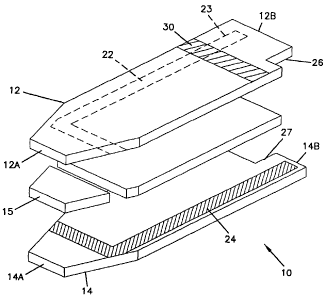
Sensor strip 10 has a first substrate 12, a second substrate 14, and a spacer
15
positioned therebetween.
Sensor strip 10 includes at least one working electrode 22 and at least
one counter electrode 24. Sensor strip 10 also includes an optional insertion
monitor 30. Sensor strip 10 has a first, distal end 10A and an opposite,
proximal end 10B. At distal end 10A, sample to be analyzed is applied to
sensor 10. Distal end 10A could be referred as 'the fill end', 'sample
receiving
end', or similar. Proximal end 10B of sensor 10 is configured for operable,
= and usually releasable, connecting to a device such as a meter.
5
CA 02659621 2009-01-30
WO 2008/016501 PCT/US2007/016554
Sensor strip 10 is a layered construction, in certain embodiments having a
generally rectangular shape, i.e., its length is longer than its width,
although
other shapes 10 are possible as well, as noted above. The length of sensor
strip
is from end 10A to end 10B.
5 The dimensions of a sensor may vary. In certain embodiments, the
overall
length of sensor strip 10 may be no less than about 10 mm and no greater than
about
50 mm. For example, the length may be between about 30 and 45 mm; e.g., about
30 to 40 mm. It is understood, however that shorter and longer sensor strips
10
could be made. In certain embodiments, the overall width of sensor strip 10
may be
10 no less than about 3 mm and no greater than about 15 mm. For example,
the width
may be between about 4 and 10 mm, about 5 to 8 mm, or about 5 to 6 mm. In one
particular example, sensor strip 10 has a length of about 32 mm and a width of
about
6 mm. In another particular example, sensor strip 10 has a length of about 40
mm
and a width of about 5 mm. In yet another particular example, sensor strip 10
has a
length of about 34 mm and a width of about 5 mm.
Briefly referring to FIGS. 3 and 4, two different configurations of a portion
of sensors are illustrated. FIG. 3 shows a portion of sensor strip 10 that
includes
first end 10A and sample chamber 20. FIG. 4 shows a portion of a sensor strip
10'
that includes a sensor first end 1OA' and a sample chamber 20'. The shape of
sensors 10, 10' is the result of physically altering the sensor's measurement
zone
during the manufacturing process to provide sensor strips 10, 10' with pre-
determined calibration. Additional details are provided below.
Substrates and Spacer
As provided above, sensor strip 10 has first and second substrates 12, 14,
non-conducting, inert substrates which form the overall shape and size of
sensor
strip 10. Substrates 12, 14 may be substantially rigid or substantially
flexible. In
certain
embodiments, substrates 12, 14 are flexible or deformable. Examples of
suitable
materials for substrates 12, 14 include, but are not limited, to polyester,
polyethylene, polycarbonate, polypropylene, nylon, and other "plastics" or
polymers.
In certain embodiments the substrate material is "Melinex" polyester. Other
non-
conducting materials may also be used.
Substrate 12 includes first or distal end 12A and second or proximal end
6
CA 02659621 2009-01-30
WO 2008/016501
PCT/US2007/016554
128, and substrate 14 includes first or distal end 14A and second or proximal
end
14B.
As indicated above, positioned between substrate 12 and substrate 14 may be
spacer 15 to separate first substrate 12 from second substrate 14. In some
embodiments, spacer 15 extends from end 10A to end 10B of sensor strip 10, or
extends short of one or both ends. Spacer 15 is an inert non-conducting
substrate,
typically at least as flexible and deformable (or as rigid) as substrates 12,
14. In
certain embodiments, spacer 15 is an adhesive layer or double-sided adhesive
tape or
film that is continuous and contiguous. Any adhesive selected for spacer 15
should
be selected to not diffuse or release material which may interfere with
accurate'
anal yte measurement.
In certain embodiments, the thickness of spacer 15 may be constant
throughout, and may be at least about 0.01 mm (10 um) and no greater than
about 1
mm or about 0.5 mm. For example, the thickness may be between about 0.02 mm
(20 pm) and about 0.2 mm (200 um). In one certain embodiment, the thickness is
about 0.05 mm (50 gm), and about 0.1 mm (100 gm) in another embodiment.
Sample Chamber
The sensor includes a sample chamber for receiving a volume of sample to
be analyzed; in the embodiment illustrated, particularly in FIG. 1, sensor
strip 10
includes sample chamber 20 having an inlet 21 for access to sample chamber 20:
In the embodiment illustrated, sensor strip 10 is a side-fill sensor strip,
having
inlet 21 present on a side edge of strip 10. Tip-fill sensors, having an inlet
at, for
example, end 10A, are also within the scope of this disclosure, as well as
corner
and top filling sensors. Sample chamber 20
is configured so that when a
sample is provided in chamber 20, the sample is in electrolytic contact with
both a
working electrode and a counter electrode, which allows electrical current to
flow
between the electrodes to effect the electrolysis (electrooxidation or
electroreduction) of the analyte.
Sample chamber 20 is defined by substrate 12, substrate 14 and spacer 15; in
many embodiments, sample chamber 20 exists between substrate 12 and substrate
14 where spacer 15 is not present. Typically, a portion of spacer 15 is
removed to
provide a volume between substrates 12, 14 without spacer 15; this volume of
removed spacer is sample chamber 20. For embodiments that include spacer 15
7
CA 02659621 2009-01-30
WO 2008/016501
PCT/US2007/016554
between substrates 12, 14, the thickness of sample chamber 20 is generally the
thickness of spacer 15.
Sample chamber 20 has a volume sufficient to receive a sample of biological
fluid therein. In some embodiments, such as when sensor strip 10 is a small
volume
sensor, sample chamber 20 has a volume that is typically no more than about 1
p.L,
for example no more than about 0.5 L, and also for example, no more than
about
0.25 p.L. A volume of no more than about 0.1 p.L is also suitable for sample
chamber 20, as are volumes of no more than about 0.05 I, and about 0.03 L.
A measurement zone is contained within sample chamber 20 and is the
region of the sample chamber that contains only that portion of the sample
that is
interrogated during the analyte assay. In some designs, the measurement zone
has a
volume that is approximately equal to the volume of sample chamber 20. In some
embodiments the measurement zone includes 80% of the sample chamber, 90% in
other embodiments, and about 100% in yet other embodiments.
As provided above, the thickness of sample chamber 20 corresponds
typically to the thickness of spacer 15. Particularly for facing electrode
configurations, as in the sensor illustrated in FIG. 2, this thickness is
small to
promote rapid electrolysis of the analyte, as more of the sample will be in
contact
with the electrode surface for a given sample volume. In addition, a thin
sample
chamber 20 helps to reduce errors from diffusion of analyte into the
measurement
zone from other portions of the sample chamber during the analyte assay,
because
diffusion time is long relative to the measurement time, which may be about 5
seconds or less.
Electrodes
As provided above, the sensor includes a working electrode and at least one
counter electrode. The counter electrode may be a counter/reference electrode.
If
multiple counter electrodes are present, one of the counter electrodes will be
a
counter electrode and one or more may be reference electrodes.
For sensor 10, at least one working electrode is positioned on one of first
substrate 12 and second substrate 14 in the measurement zone and/or sample
chamber. In FIG. 2, working electrode 22 is illustrated on substrate 12.
Working
electrode 22 extends from the sample chamber 20, proximate distal end 10A, to
the
other end of the sensor 10, end 10B, as an electrode extension called a
"trace". The
8 =
CA 02659621 2009-01-30
WO 2008/016501 PCT/US2007/016554
trace provides a contact pad 23 for providing electrical connection to a meter
or
other device to allow for data and measurement collection, as will be
described later.
Contact pad 23 may be positioned on a tab 26 that extends from the substrate
on
which working electrode 22 is positioned, such as substrate 12. hi some
embodiments, a tab has more than one contact pad positioned thereon. In
alternate
embodiments, a single contact pad is used to provide a connection to one or
more
electrodes; that is, multiple electrodes are coupled together and are
connected via
one contact pad.
Working electrode 22 may be a layer of conductive material such as
gold, carbon, platinum, ruthenium dioxide, palladium, or other non-corroding,
conducting material. Working electrode 22 may be a combination of two or
more conductive materials. An example of a suitable conductive epoxy is
ECCOCOAT CT5079-3 Carbon-Filled Conductive Epoxy Coating (available
from W.R. Grace Company, Woburn, MA). The material of working electrode
22 typically has relatively low electrical resistance and is typically
electrochemically inert over the potential range of the sensor during
operation.
Working electrode 22 may be applied on substrate 12 by any of various
methods, 30 including by being deposited, such as by vapor deposition or
vacuum
deposition or otherwise sputtered, printed on a flat surface or in an embossed
or
otherwise recessed surface, transferred from a separate carrier or liner,
etched, or
molded. Suitable methods of printing include screen-printing, piezoelectric
printing,
ink jet printing, laser printing, photolithography, and painting.
As provided above, at least a portion of working electrode 22 is provided in
sample chamber 20 for the analysis of analyte, in conjunction with the counter
electrode.
The sensor includes at least one counter electrode positioned within the
measurement zone and/or sample chamber. In FIG. 2, counter electrode 24 is
illustrated on substrate 14. In alternate embodiments, a counter electrode is
present
on a different surface or substrate, such as substrate 12. Counter electrode
24
extends from the sample chamber 20, proximate first end 10A, to the other end
of
the sensor 10, end 10B, as an electrode extension called a "trace". The trace
provides
a contact pad 25 for providing electrical connection to a meter or other
device to
allow for data and measurement collection, as will be described later. Contact
pad 25
may be positioned on a tab 27 that extends from the substrate on which counter
9
CA 02659621 2009-01-30
WO 2008/016501 PCT/US2007/016554
electrode 24 is positioned, such as substrate 12 or 14. In some embodiments, a
tab
has more than one contact pad positioned thereon. In alternate embodiments, a
single contact pad is used to provide a connection to one or more electrodes;
that is,
multiple electrodes are coupled together and are connected via one contact
pad.
Counter electrode 24 may be constructed in a manner similar to working
electrode 22. Suitable materials for the counter/reference or reference
electrode
include Ag/AgC1 or Ag/AgBr on a non-conducting base material or silver
chloride
on a silver metal base. The same materials and methods may be used for counter
electrode 24 as are available for working electrode 22, although different
materials
and methods may also be used. Counter electrode 24 may include a mix of
multiple
conducting materials, such as Ag/AgCI and carbon.
Working electrode 22 and counter electrode 24 may be disposed opposite to
and facing each other to form facing electrodes. See for example, FIG. 2,
which
has working electrode 22 on substrate 12 and counter electrode 24 on substrate
14,
forming facing electrodes: In this configuration, the sample chamber is
typically
present between the two electrodes 22, 24. Working electrode 22 and counter
electrode 24 may alternately be positioned generally planar to one another,
such as
on the same substrate, to form co-planar or planar electrodes. .
In some instances, it is desirable to be able to determine when the sample
chamber of the sensor is sufficiently filled with sample. Sensor strip 10 may
be
indicated as filled, or substantially filled, by observing a signal between an
optional
indicator electrode and one or both of working electrode 22 or 'counter
electrode 24
as sample chamber 20 fills with fluid. When fluid reaches the indicator
electrode,
the signal from that electrode will change_ Suitable signals for observing
include,
for example, voltage, current, resistance, impedance, or capacitance between
the
indicator electrode and, for example, working electrode 22. Alternatively, the
sensor
may be observed after filling to determine if a value of the signal (e.g.,
voltage,
current, resistance, impedance, or capacitance) has been reached indicating
that the
sample chamber is filled.
Typically, the indicator electrode is further downstream from a sample
inlet, such as inlet 21, than working electrode 22 and/or counter electrode
24.
For side-fill sensors, such as sensor 10 of FIGS. 1 and 2, an indicator
electrode may be present on each side of the counter electrode. This permits
the
user to fill the sample chamber from either the left or right side with an
indicator
CA 02659621 2009-01-30
WO 2008/016501
PCT/US2007/016554
electrode disposed further upstream. This three-electrode configuration is not
necessary. Side-fill sensors may also have a single indicator electrode and
may
include some indication as to which side should be placed in contact with the
sample fluid.
The indicator electrode may also be used to improve the precision of the
analyte measurements. The indicator electrode may operate as a working
electrode
or as a counter electrode or counter/reference electrode. Measurements from
the
indicator electrode/working electrode may be combined (e.g., added or
averaged)
with those from the first counter/reference electrode/working electrode to
obtain
more accurate measurements.
The sensor or equipment that the sensor connected is with (e.g., a meter)
may include a signal (4, a visual sign or auditory tone) that is activated in
response to activation of the indicator electrode to alert the user that the
desired
zone has been filled. The sensor or equipment may be configured to initiate a
reading when the indicator electrode indicates that the measurement zone has
been filled with or without alerting the user. The reading may be initiated,
for
example, by applying a potential between the working electrode and the counter
electrode and beginning to monitor the signals generated at the working
electrode.
Sensing Chemistry
In addition to working electrode 22, sensing chemistry material(s) are
preferably provided in sample chamber 20 for the analysis of the analyte.
Sensing
chemistry material facilitates the transfer of electrons between working
electrode 22
and the analyte in the sample. Any sensing chemistry may be used in sensor
strip
10; the sensing chemistry may include one or more materials.
The sensing chemistry may be diffusible or leachable, or non-diffusible or
non-leachable. For purposes of discussion herein, the term "diffusible" will
be used
to represent "diffusible or leachable" and the term "non-diffusible" will be
used to
represent "non-diffusible or non-leachable" and variations thereof. Placement
of
sensing chemistry components may depend on whether they are diffusible or not.
For example, both non- diffusible and/or diffusible component(s) may form a
sensing layer on working electrode 22. Alternatively, one or more diffusible
components may be present on any surface in sample chamber 20 prior to the
11
CA 02659621 2009-01-30
WO 2008/016501 PCT/US2007/016554
introduction of the sample to be analyzed; As another example, one or more
diffusible component(s) may be placed in the sample prior to introduction of
the
sample into sample chamber 20.
The sensing chemistry generally includes an electron transfer agent that
facilitates the transfer of electrons to or from the analyte. The electron
transfer agent
may be diffusible or non-diffusible, and may be present on working electrode
22 as a
layer. One example of a suitable electron transfer agent is an enzyme which
catalyzes a reaction of the analyte. For example, a glucose oxidase or glucose
dehydrogenase, such as pyrroloquinoline quinone glucose dehydrogenase (PQQ),
is
used when the analyte is glucose. Other enzymes may be used for other
analytes. =
The electron transfer agent, whether it is diffusible or not, facilitates a
current between working electrode 22 and the analyte and enables the
electrochemical analysis of molecules. The agent facilitates the transfer
electrons
between the electrode and the analyte.
This sensing chemistry may, additionally to or alternatively to the electron
transfer agent, include a redox mediator. Certain embodiments use a redox
mediator
that is a transition metal compound or complex. Examples of suitable
transition
metal compounds or complexes include osmium, ruthenium, iron, and cobalt
compounds or complexes. In these complexes, the transition metal is
coordinatively
bound to one or more ligands, which are typically mono-, di-, tri-, or
tetradentate.
The redox mediator may be a polymeric redox mediator or a redox polymer (i.e.,
a
polymer having one or more redox species). Examples of suitable redox
mediators
and redox polymers are disclosed in U.S. Patent No. 6,338,790, for example,
and in
U.S. Patent Nos. 6,605,200 and 6,605,201.
If the redox mediator is non-diffusible, then the redox mediator may be
present on working electrode 22 as a layer. In an embodiment having a redox
mediator and an electron transfer agent, if the redox mediator and electron
transfer
agent are both non-leachable, then both components are on working electrode 22
as
individual layers, or combined and applied as a single layer.
The redox mediator, whether diffusible or not, mediates a current between
working electrode 22 and the analyte and enables the electrochemical analysis
of
molecules which may not be suited for direct electrochemical reaction on an
electrode. The mediator functions as an agent to transfer electrons between
the
electrode and the anal yte.
12
CA 02659621 2009-01-30
WO 2008/016501
PCT/US2007/016554
Insertion Monitor
The sensor may include an indicator to notify when proper insertion of the
sensor into receiving equipment, such as a meter, has occurred. As seen in
FIGS. 1
and 2, sensor strip 10 includes insertion monitor 30 on an exterior surface of
one of
substrates 12, 14, in the illustrated sensor, sensor 10. Insertion monitor 30
is
configured and arranged to close an electrical circuit when sensor 10 is
properly
inserted into the meter connector.
Insertion monitor 30 may be a stripe extending across an exterior surface of
sensor 10, for example, from side edge to side edge, with one contact pad for
connection to a meter. It is understood that in alternate embodiments of the
insertion
monitor, the stripe need not extend to both side edges. In other embodiments,
the
insertion monitor may be two or more contact pads for connection to a meter.
The
two or more contact pads could electrically connected to each other by a
material,
such as a conductive ink.
Insertion monitor 30 can be used to encode information regarding sensor
strip 10. The encoded information may be, for example, the test time needed
for
accurate analyte concentration analysis, the expiration date of sensor strip
10,
various correction factors, such as for environmental temperature and/or
pressure,
selection of the analyte to be analyzed (e.g., glucose, ketone, lactate), and
the like.
Additionally, insertion monitor 30 can be used to encode calibration
information for
the sensor, e.g., for the manufacturing lot or that specific sensor strip.
However, in
accordance with this disclosure, the sensor requires no calibration code;
rather, the
sensor is configured with a pre-determined calibration, based on the volume of
the
measurement zone.
Additional details regarding insertion monitors, and their use for encoding
information, are described, for example, in U.S. Patent application
publication no.
2006/0091006 Al. Additionally, U.S. Patent application publication no.
2006/0091006 Al provides various details regarding connection of sensors with
insertion monitors with meters and connectors.
Referring to FIGS. 5 and 6 in particular, an alternate embodiment of a sensor
is illustrated as sensor strip 110. Similar to sensor strip 10, sensor strip
110 has a
first substrate 112, a second substrate 114, and a spacer 115 positioned .
therebetween. Sensor strip 110 includes at least one working electrode 122 and
at
13
CA 02659621 2009-01-30
WO 2008/016501 PCT/US2007/016554
least one counter electrode 124.
Sensor strip 110 has a first, distal end 110A and an opposite, proximal end
110B. At distal end 110A, sample to be analyzed is applied to sensor 110.
Distal
end 110A 30 could be referred as 'the fill end', 'sample receiving end', or
similar.
Proximal end 110B of sensor 110 is configured for operable, and preferably
releasable, connecting to a device such as a meter. Similar to sensor strip
10, sensor
strip 110 is a layered construction, in certain embodiments having a generally
rectangular shape, which is formed by first and second substrates 112, 114.
Substrate 112 includes first or distal end 112A and second or proximal end
112B,
and substrate 114 includes first or distal end 114A and second or proximal end
114B. The discussion above about substrates 12, 14 and spacer 15 applies to
substrates 112, 114 and spacer 15.
Sensor strip 110 includes sample chamber 120 having an inlet 121 for
access to sample chamber 120. Sensor strip 110 is a tip-fill sensor, having
inlet
121 at end 110A.
Similar to sample chamber 20 of sensor strip 10, sample chamber 120 is
defined by substrate 112, substrate 114 and spacer 115. Generally opposite to
inlet
121, through substrate 112 is a vent 130 from sample chamber 120. The
discussion
above about sample chamber 20 and its measurement zone applies to sample
chamber 120.
For sensor 110, at least one working electrode 122 is illustrated on substrate
114. Working electrode 122 extends from end 114A into sample chamber 120 to
end 114B and 11013. Sensor 110 also includes at least one counter electrode
124, in
this embodiment on substrate 114. Counter electrode 124 extends from sample
chamber 120, proximate first end 110A, to end 110B, as an electrode extension
called a "trace". Working electrode 122 and counter electrode 124 are present
on the
same substrate e.g., as planar or co-planar electrodes. The electrodes 122,
124 may
include sensing chemistry material(s) thereon.
General Method for Manufacturing Sensors
Sensor strips 10, 110 discussed above, are sandwiched or layered
constructions having substrates 12, 14, 112, 114 spaced apart, such as by
spacer 15,
115. Such a construction may be made by laminating the various layers
together, in
any suitable manner. An alternate method for making sensor strips 10, 110, and
14
CA 02659621 2009-01-30
WO 2008/016501 PCT/US2007/016554
other sensors in accordance with the invention, is to mold the sensors.
Molding may include positioning at least two spaced apart electrically 30
conductive electrodes (e.g., wires) in a mold, and molding a body of
insulative
material around the electrodes, with one end having therein means for
receiving a
fluid sample. More specifically, molding could include positioning at least
two
spaced apart electrically conductive electrodes (e.g., wires) in a mold,
before or
after molding, treating at least one of the electrodes with one or more
chemicals to
change the electrical properties of the treated electrode upon contact with a
fluid
sample, and molding a body of insulative material around the electrodes with
one
end having therein means for receiving a fluid sample. The body may be molded
in multiple pieces, e.g., two pieces, with a body and end cap for attaching to
one
= another after the molding is completed, or in a single piece.
A sensor may be made by positioning electrodes on one or more
substrates, the substrates including a first substrate, optionally contacting
at least a
portion of at least one electrode with sensing material(s), and configuring
the
sensor by positioning a spacer between the two substrates to maintain the
substrates in a fixed, layered orientation relative to each other.
Calibration of Sensors
Whether the sensors are laminated, molded, or made by some other process,
after or during forming the sensor, a portion of the sensor is physically
modified
(e.g., removed, re-shaped, reacted, etc.) to provide the sensor with a pre-
determined
slope and y-intercept. Typically, the physically modified portion of the
sensor
includes the sample chamber and/or measurement zone. In accordance with some
embodiments of this disclosure, the sample chamber shape and/or size is
altered to
provide the sensor with the desired pre-determined slope and y-intercept. In
many
embodiments, the shape and/or size of the sample chamber and/or measurement
zone is physically modified. Additionally or alternately, in accordance with
some
embodiments of this disclosure, the electrode area within the sample chamber
and/or
measurement zone is altered, sometimes without altering the sample chamber
shape
and/or size. In many embodiments, the electrode area is physically modified.
Referring again to FIGS. 3 and 4, two different configurations of sensors are
30 illustrated. FIG. 3 shows a portion of sensor strip 10 that includes first
end 10A
and FIG. 4 shows a portion of a sensor strip 10' that includes a sensor first
end 10A'.
CA 02659621 2009-01-30
WO 2008/016501
PCT/US2007/016554
Sensor strip 10 includes first edge 102 (which in this embodiment is also
sensor end
10A), second edge 104 and third edge 106, each of which is a straight, linear
edge.
The corners formed by the meeting of edges 104, 106 with edge 102 are angular,
in
this embodiment, having an internal angle of about 108 degrees. In this
embodiment, sample chamber 20 extends across sensor strip 10 from edge 104 to
edge 106. Sensor strip 10' includes first edge 102' (which in this embodiment
is also
sensor end 10A1), second edge.104' and third edge 106'. Edges 104' and 106'
are
arcuate edges. Additionally, the corners formed by the meeting of edges 104',
106'
with edge 102' are rounded or radiused. Also in this embodiment, sample
chamber
20' extends across sensor 10' from edge 104' to edge 106'. The volume of
sample
chamber 20, 20' is defined by side edges 104, 104' and 106, 106' and the
thickness of
the sample chamber.
To clarify understanding, the following discussion will use the term "pre-
sensor" when referring to the sensor prior to any physical alteration of the
sensor.
Sensors 10, 10' are the result of physically altering the sample chamber
and/or measurement zone after the manufacturing process of the pre-sensor to
provide sensors that have a pre-determined slope and y-intercept. In some
embodiments, "physically altering" includes removing a portion of the sample
=
chamber and/or measurement zone of the pre-sensor. FIG. 3 illustrates a first
phantom portion 104' (i.e., 104 superscript naught), which corresponds to the
portion of the pre-sensor removed to form edge 104, and a second phantom
portion 106 (i.e., 106 superscript naught), which corresponds to the portion
of the
pre-sensor removed to form edge 106. By removing phantom portions 1040, 106',
a portion of the sample chamber, i.e., that present in portions 104 , 106 , is
also
removed, thus physically altering the pre-sensor. For sensors 10, 10' of FIGS.
3
and 4, the calibration code is proportional to the volume of the measurement
zone
and/or the sample chamber of the sensor.
Referring to FIG. 5, sensor 110 is the result of physically altering the
electrode area and the sample chamber and/or measurement zone after the
manufacturing process of the pre-sensor to provide sensors that have a pre-
determined slope and y-intercept. FIG. 5 illustrates phantom portion 110
(i.e., 110
superscript naught), which corresponds to the portion of the pre-sensor
removed to
form edge 110A. By removing phantom portion 110 , a portion of the working
electrode 122, i.e., that present on substrate 114 within phantom portion
1100, is
16
CA 02659621 2009-01-30
WO 2008/016501 PCT/US2007/016554
also removed, thus physically altering the pre-sensor. For sensor 110 above,
the
calibration slope and y-intercept are proportional to the area of the
electrode(s),
e.g., working electrode 122, in the sample chamber of the sensor. In this
embodiment, the volume of the sample chamber is reduced, due to the removal of
phantom portion 110 . It is noted that in alternate embodiments, the sample
chamber volume and/or measurement zone volume may remain the same although
the area of the electrodes is modified. One exemplary method for modifying the
electrode area, e.g., removing area, is by the use of non-invasive procedures,
such
as a single or multiple energy beams (e.g., lasers, UV light, electron beam,
etc.)
that pass through the inert substrates but physically alter the electrodes. In
this
process, areas of electrode(s) may be removed or otherwise rendered inactive.
To provide a plurality of sensors, such as sensor strips 10, 10', 110 with the
same pre-determined calibration from a plurality of pre-sensors, each of the
pre-
sensors may be physically altered, as needed, to obtain the desired pre-
determined
physical characteristics and the desired sensor. It is understood that this
discussion
also applies to a batch or lot of sensors in addition to a single sensor. For
example,
a first pre-sensor may have a response that is too high compared to the
desired
level and a second pre-sensor may have a response that is within the desired
level.
In such a situation, a portion of the first pre-sensor may be removed to
provide a
sensor having a measurement zone, sample chamber, or electrode area that is
comparable to that of the second pre-sensor and is within the desired level.
In some situations, however, a pre-sensor, e.g., a third sensor strip, may
have a response that is too low compared to the desired level. Because in most
embodiments it would be difficult or impractical to increase the measurement
zone,
sample chamber, and/or electrode area of the pre-sensor after it has been
assembled, in some manufacturing operations the desired response level may be
artificially lowered in order to pre-calibrate the sensor. With such an
artificially
lowered desired level, for a pre-sensor that has a response within that
desired
artificially low level, a pre-determined portion of the pre-sensor's active
area may
be removed to obtain a sensor with the actual desired level; for a pre-sensor
that
has a response above the desired artificially low, a larger portion than the
pre-
determined portion of the pre-sensor's active area may be removed to obtain a
sensor with the actual desired level; and for a pre-sensor that has a response
below
the desired artificially low level, a smaller portion than the pre-determined
portion
17
CA 02659621 2009-01-30
WO 2008/016501
PCT/US2007/016554
of the pre-sensor's active area is removed in orderto obtain a sensor with the
actual
desired level. In other words, using such a methodology, all the pre-sensors
would
be physically altered to obtain sensors with the same desired predetermined
calibration.
The pre-sensor is modified in order to obtain the desired pre-determined
calibration, either by altering the volume of the sample chamber and/or
measurement zone or by the electrode area in the sample chamber. Referring to
FIGS. 3 and 4, in this embodiment, the volume of the sample chamber and/or
measurement zone is modified by removing phantom portions 104 , 106 , and the
electrode area is modified in FIG. 5 by removing phantom portion 110 .
In some embodiments, there may be no actual pre-sensor that is subsequently
modified to form the sensor, but rather, a pre-sensor is used as a template
for one or
more sensors (e.g., batch or lot of sensors, e.g., at least 100 sensors, at
least 1,000
sensors, or even at least 50,000 sensors). For example, multiple sensors may
be
obtained from, e.g., a large sheet construction having working electrodes,
counter
electrodes and sample chambers. See for example, U.S. Patent No. 6,338,790,
particularly FIGS. 31A and 31B and the description associated therewith, which
describes methods of making a plurality of sensors from a large sandwiched
sheet
construction. From this sheet, one (or more) test sensors could be removed
(e.g.,
punched) using a standard template (e.g., shape and size), and these test
sensors
could be tested for their difference from the desired slope and y-intercept,
and the
results typically averaged. Subsequently removed sensors would be modified
from
the test sensor, as needed, by removing (e.g., punching) an appropriately
shaped and
sized sensor, which may differ from the test sensors, to obtain the desired
slope and
y-intercept. In this method, the test sensors provide a guide for the
modification
needed, so that each sensor is not individually tested.
It is understood that other configurations of phantom portions would be
suitable. For example, sensor 10 of FIG. 3 has edge 102 and edges 104, 106
forming an angle of about 108 degrees. This corner angle could be about 90
degrees
or be a high as 180 degrees; in most embodiments, however, this corner angle
is in
the range of about 90 to about 145 degrees. Angles less than 90 degrees could
be
used for a concave edge 102, 102'. The comers could be sharp, as in FIG. 3, or
rounded, as in FIG. 4. Any or all of edges 102, 104, 106 may be straight or
curved,
with concave, convex, or a combination of shapes. Both sensor strips 10, 10'
have
18
CA 02659621 2009-01-30
WO 2008/016501 PCT/US2007/016554
edge 102, 102' forming end 10A, 10A'; in alternate embodiments, the sensor end
could be defined by the meeting of edges 104, 106 (i.e., the side edges meet
at a
point with no end edge). In some embodiments, the sensor could be
asymmetrical,
e.g., having only one portion removed from the sensor. Other shapes for
sensors
would be suitable. FIGS. 5 and 6 illustrate sensor strip 110 with a blunt end
110A,
having 90 degree corners. After providing any of sensors 10, 10', 110, the
proximal
ends, e.g., 10B, 110B could be adjusted so that all sensors in the lot have
the same
final size.
Application of the Sensor
A common use for a sensor of the present invention, such as sensor strip 10,
10' 110, is for the determination of analyte concentration in a biological
fluid, such =
as glucose concentration in blood, interstitial fluid, and the like, in a
patient or other
user. Additional analytes that may be determined include but are not limited
to, for
example, acetyl choline, amylase, bilirubin, cholesterol, chorionic
gonadotropin,
creatine kinase (e.g., CK-MB), creatine, DNA, fructosamine, glucose,
glutamine,
growth hormones, hormones, ketones, lactate, peroxide, prostate-specific
antigen,
prothrombin, RNA, thyroid stiMulating hormone, and troponin. The concentration
of drugs, such as, for example, antibiotics (e.g., gentamicin, vancomycin, and
the
like), digitoxin; digoxin, drugs of abuse, theophylline, and warfarin, may
also be
determined.
Sensors may be available at pharmacies, hospitals, clinics, from doctors, and
other sources of medical devices. Multiple sensors may be packaged together
and
sold as a single unit; e.g., a package of about 25, about 50, or about 100
sensors, or
any other suitable number. A kit may include one or more sensors, and
additional
components such as control solutions and/or lancing device and/or meter, etc.
Sensors may be used for an electrochemical assay, or, for a photometric test.
Sensors are generally configured for use with an electrical meter, which may
be
connectable to various electronics. A meter may be available at generally the
same
locations as the sensors, and sometimes may be packaged together with the
sensors,
e.g., as a kit.
Examples of suitable electronics connectable to the meter include a data
processing terminal, such as a personal computer (PC), a portable computer
such as
a laptop or a handheld device (e.g., personal digital assistants (PDAs)), and
the
19
CA 02659621 2009-01-30
WO 2008/016501
PCT/US2007/016554
like. The electronics are configured for data communication with the receiver
via a
wired or a wireless connection. Additionally, the electronics may further be
connected to a data network (not shown) for storing, retrieving and updating
data
corresponding to the detected glucose level of the user.
The various devices connected to the meter may wirelessly communicate
with a server device, e.g., using a common standard such as 802.11 or
Bluetooth
RF protocol, or an IrDA infrared protocol. The server device could be another
portable device, such as a Personal Digital Assistant (PDA) or notebook
computer,
or a larger device such as a desktop computer, appliance, etc. In some
embodiments, the server device has a display, such as a liquid crystal display
(LCD), as well as an input device, such as buttons, a keyboard, mouse or touch-
screen. With such an arrangement, the user can control the meter indirectly by
interacting with the user interface(s) of the server device, which in turn
interacts
with the meter across a wireless link.
The server device may also communicate with another device, such as for
sending data from the meter and/or the service device to a data storage or
computer.
For example, the service device could send and/or receive instructions (e.g.,
an
insulin pump protocol) from a health care provider computer. Examples of such
communications include a PDA synching data with a personal computer (PC), a
mobile phone communicating over a cellular network with a computer at the
other
end, or a household appliance communicating with a computer system at a
physician's office.
A lancing device or other mechanism to obtain a sample of biological fluid,
e.g., blood, from the patient or user may also be available at generally the
same
locations as the sensors and the meter, and sometimes may be packaged together
with the sensor and/or meter, e.g., as a kit.
The sensors are particularly suited for inclusion in an integrated device,
i.e.,
a device which has the sensor and a second element, such as a meter or a
lancing
device, in the device. The integrated device may be based on providing an
electrochemical assay or a photometric assay. In some embodiments, sensors may
be integrated with both a meter and a lancing device. Having multiple elements
together in one device reduces the number of devices needed to obtain an
analyte
level and facilitates the sampling process. For example, embodiments may
include
a housing that includes one or more of the sensor strips, a skin piercing
element
= 20
CA 02659621 2014-11-14
and a processor for determining the concentration of an analyte in a sample
applied
to the strip. A plurality of sensors may be retained in a cassette in the
housing
interior and, upon actuation by a user, a single sensor may be dispensed from
the
cassette so that at least a portion extends out of the housing for use.
Operation of the Sensor Strip
In use, a sample of biological fluid is provided into the sample chamber of
the sensor, where the level of analyte is determined. The analysis may be
based on
providing an electrochemical assay or a photometric assay. In many
embodiments,
it is the level of glucose in blood that is determined. Also in many
embodiments, the
source of the biological fluid is a drop of blood drawn from a patient, e.g.,
after
piercing the patient's skin with a lancing device, which could be present in
an
integrated device, together with the sensor strip.
Prior to providing the sample to the sensor, or even after providing the
sample to the sensor, there is no need for the user to input a calibration
code or other
information regarding the operation and/or interaction of the sensor with the
meter
or other equipment.. The sensor is configured so that the results received
from the
analysis are clinically accurate, without the user having to adjust the sensor
or the
meter. The sensor is physically configured to provide accurate results that
are
repeatable by a batch of sensors.
After receipt of the sample in the sensor, the analyte in the sample' is,
e.g.,
electrooxidized or electroreduced, at the working electrode and the level of
current
obtained at the counter electrode is correlated as analyte concentration. The
sensor
may be operated with or without applying a potential to the electrodes. In one
embodiment, the electrochemical reaction occurs spontaneously and a potential
need
not be applied between the working electrode and the counter electrode. In
another
embodiment, a potential is applied between the working electrode and the
counter
electrode.
The invention has been described with reference to various specific and
preferred embodiments and techniques. However, it will be apparent to one of
ordinarily skill in the art that the scope of the claims should not be limited
by the
preferred embodiments set forth in the examples, but should be given the
broadest
interpretation consistent with the description as a whole. It is understood
that elements
or features present on one embodiment described above could be used on other
21
CA 02659621 2009-01-30
WO 2008/016501
PCT/US2007/016554
embodiments. For example, the discussion above has been directed to modifying
the sensor based on an output (e.g., charge) from an assembled sensor. In an
alternate embodiment, individual components or materials of the sensor could
be
tested prior to assembling the sensor, and then modifying the sensor as needed
to
compensate for the previous test. For example, the sensing chemistry activity
may
be tested prior to incorporation of the chemistry in a sensor. If, for
example, the
activity is below the desired standard, when incorporated into sensor, the
sensors
could be physically adjusted (e.g., sample chamber volume or electrode area
increased) to compensate for the low chemistry activity. Similarly, if the
activity is
above the desired standard, when incorporated into sensor, the sensors could
be
physically adjusted (e.g., sample chamber volume or electrode area decreased)
to
compensate for the high chemistry activity.
=
22
CA 02659621 2014-11-14
=
Experimental =
Five sensor strips, each having a distal end similar to that illustrated in
FIG. 4, were punched from a laminated sheet composed of two substrates and a
spacer layer therebetween, with at least one working electrode and at least
one
counter electrode in facing configuration. Each of the sensor strips had
arcuate
edges, similar to edges 104', 106' in FIG. 4. The table below provides
parameters
for the five sensor strips. The "tip distance" was the distance between the
distal
= most end of the sensor strip (e.g., end 10Al in FIG. 4) and the sample
chamber
(e.g., sample chamber 20' in FIG. 4). The punch that formed the distal end and
the
arcuate edges was the same punch for each of the sensor strips. Thus, as the
distance between the tip and the sample chamber increased, the length of the
sample chamber (between the arcuate edges) increased, thus increasing the
sample
chamber volume.
Tip distance Sample chamber volume Charge
(0.001 inch) (nanoliter)
(microcoulombs)
10 97 98.7
=
103 107.7
109 115.9
114 123.4
120
127.9
15 This data shows a linear relationship between the sample chamber volume
and the measured charge; the linear equation is y=1.3x - 26.4. Also, the data
shows
a linear relationship between the tip distance and the measured charge; the
linear
equation is y=0-.74x + 92.5. With this knowledge, the punch position to
achieve the
desired sensor response for this batch of sensors can be calculated.
20 All patents and other references in this specification are indicative of
the
level of ordinary skill in the art to which this invention pertains.
23