Note: Descriptions are shown in the official language in which they were submitted.
CA 02659988 2012-02-23
TAMPER RESISTANT METER COVER
BACKGROUND
(00021 The embodiments described herein relate generally to electrical energy
meters, and in particular to a meter having a tamper-resistant or tamper-
evident cover.
100031 Electrical energy meters, also referred to as "watt-hour meters," are
used
on a widespread basis in residential, commercial, and industrial applications
to measure
the amounts of utility, such as electricity, gas, and the like, that are being
utilized by
customers. Meters are typically mounted on an exterior or interior wall of a
building being
monitored, and generally include a base and a cover attached to the base. The
base
supports a rate metering device attached to a power box, and a utility usage
display. The
cover can be substantially clear or include a clear portion that allows the
usage display to
be viewed through the cover.
-1-
CA 02659988 2009-03-25
ELSE-1139
[00041 Referring to Figs. 1 and 2, a conventionally constructed meter 20 is
schematically illustrated as including a base 22 having a mounting location 24
that
supports the rate metering device (not shown), and a cover 26 attached to the
base 22. The
base 22 includes an outer lip 31 that defines the perimeter of the cover 26,
and is sized to
fit over the perimeter of the base 22. The base 22 further includes a
plurality of
circumferentially spaced retention lugs 30 that extend radially in from the
lip 31. Each
retention lug 30 can define a retention pocket 32 configured to receive a
complementary
plurality of locking members 33 that are circumferentially spaced about the
perimeter of
the base 22. A stop plate 34 is disposed at one end of the locking member 33
on the base
22. The meter 20 can thus be assembled by fitting the cover 26 over the base
22 such that
the retention pockets 32 are aligned with the locking members 33.
[00051 The cover 26 can then be rotated in a direction (Arrow A as
illustrated)
that causes the retention pockets 32 to receive the complementary locking
members 33.
Engagement between the stop plates 34 and the retention lugs 30 prevent over-
rotation of
the cover 26. The locking members 33 can have a thickness that causes a
pressure-fit with
the retention lugs 30 inside the pockets 32 that resists but does not prevent
counter-rotation
(in the direction of Arrow B) that detaches the cover 26 from the base 22.
[00061 It has been a goal of conventional energy meter design to provide
tamper
resistant meters. Meter covers were historically made from glass to provide
transparency
that enabled viewing of usage display. Unfortunately, the glass covers were
subject to
breakage by vandals. The development of impact resistant plastic such as
polycarbonate
allowed for plastic covers to replace the conventional glass covers to greatly
reduce
vandalism. Covers can further be provided with a seal that is installed
between the meter
base and the cover to substantially prevent relative rotation, thereby
substantially
preventing tampering due to rotational detachment of the cover from the base.
Unfortunately, conventional electrical meters were subject to tampering by
prying the
meter cover off of the base. Because the conventional meter cover could
subsequently be
fitted over the base into its original configuration, the indications (if any)
would be sparse
that the meter had been tampered with.
[00071 It is therefore desired to provide an electrical meter that has a
reduced
exposure to tampering, or is tamper evident.
-2-
CA 02659988 2009-03-25
ELSE-1139
SUMMARY
[00081 In accordance with one embodiment, an electrical meter cover is
provided
that is configured to be mounted onto an electrical meter base of the type
defining a
substantially cylindrical body, and a locking member carried by the
cylindrical body. The
electrical meter cover body includes a substantially cylindrical cover body
defining an
axially outer closed end, and an opposing axially inner open end. The meter
cover body
further includes a radial flange defining a radially inner end connected to
the open and of
the cover body, and an opposing radially outer end. A lip extends axially
inward from the
radially outer end of the flange. A retention lug defines a retention pocket
that is
configured to receive the locking member of the meter cover to secure the
meter cover
onto the meter base. The pocket defines a proximal insertion end and an
opposing distal
end. A retention rib is disposed outside the pocket and juxtaposed with the
distal end of
the pocket so as to limit access to the pocket once the meter cover has been
secured onto
the meter base.
BRIEF DESCRIPTION OF THE DRAWINGS
[00091 The embodiments described below will be better understood, and its
numerous objects and advantages will become apparent to those skilled in the
art by
reference to the following detailed description when taken in conjunction with
the
following drawings, in which:
[00101 Fig. 1 is a bottom plan view of an electrical meter assembly including
a
base and a cover constructed in accordance with the prior art;
[00111 Fig. 2 is a rear perspective view of the cover illustrated in Fig. 1;
[00121 Fig. 3 is a rear perspective view of a cover constructed in accordance
with
one embodiment;
[00131 Fig. 4 is a bottom plan view of an electrical meter assembly including
a
portion of the base and the cover illustrated in Fig. 3, wherein the base is
aligned with the
cover for installation;
[00141 Fig. 5 is a rear perspective view of the electrical meter assembly
illustrated in Fig. 4, wherein the meter cover is in an installed
configuration;
[00151 Fig. 6 is a section view taken through a portion of the electrical
meter
assembly illustrated in Fig. 5;
-3-
CA 02659988 2009-03-25
ELSE-1139
[0016] Fig. 7 is a section view similar to Fig. 6, but showing a meter
assembly
including a meter base and a meter cover both constructed in accordance with
an
alternative embodiment;
[0017] Fig. 8 is a perspective view of the meter cover illustrated in Fig. 7;
and
[0018] Fig. 9 is a rear perspective view of the base illustrated in Fig. 7;
[0019] Fig. 10 is a partial perspective view of a meter assembly including a
meter
base and a meter cover, both constructed in accordance with yet another
alternative
embodiment;
[0020] Fig. 11 is a perspective view of meter the cover illustrated in Fig.
10; and
[0021] Fig. 12 is a partial perspective view of the base illustrated in Fig.
10.
DETAILED DESCRIPTION OF ILLUSTRATIVE EMBODIMENTS
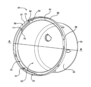
[0022] Referring to Figs. 3-5, an electrical energy meter assembly 50 can
include
a meter cover 54 configured to attach to a meter base 52. The meter assembly
50 can
contain or support an electrical energy meter, such as an electrical watt-hour
meter.
[0023] Referring in particular to Fig. 3, the illustrated meter cover 54
includes a
substantially cylindrical body 56 extending axially along an axial axis A-A,
and further
extending radially about axis A-A. The cylindrical body defines a first, or
axially inner,
open end 58 and a second, or axially outer, closed end 60. The body 56 and
closed outer
end 60 define an internal void 62 configured to receive the inner workings
(not shown) of
an electrical energy meter. The closure at the outer end 60 of the body 56 can
be
transparent, semitransparent, or include one or more portions that can be
transparent or
semitransparent.
[0024] It should be appreciated that the terms "axially" and "radially" are
used
herein to describe directions relative to axis A-A. Accordingly, a radially
inward direction
refers to a direction toward axis A-A, while a radially outward direction
refers to a
direction away from axis A-A. Likewise, an axially outer direction refers to a
direction
from the axially inner end 58 of the cover towards the axially outer end 60 of
the cover 54.
An axially inner direction refers to a direction from the axially outer end 60
of the cover
54 toward the axially inner end 58 of the cover 54.
[0025] The cover 54 can include a radial flange 64 that projects radially out
from,
and extends circumferentially about, the first end 58 of the cover body 56.
Thus, the
flange can define a radially inner end that can be integrally connected to the
first end 58 of
-4-
CA 02659988 2009-03-25
ELSE-1139
the cover body 56, and an opposing radially outer end, or perimeter. An axial
cover lip 66
can extend axially inward from the radially outer end of the flange 64. Thus,
the cover lip
66 can define an axially outer end that is connected to the radially outer end
of the flange,
and an opposing axially inner end. The cover lip 66 is sized to fit over the
meter base 52,
and thus the outer diameter of the cover lip 66 can define the footprint of
the cover 54.
[0026] A plurality of retention lugs 68 can each be provided in the form of a
radial plate 67 that projects radially inward from the axially inner end of
the lip 66. Thus,
the plate 67 can define a radially outer end that is integrally connected to
the axially inner
end of the lip 66, and an opposing radially inner end. As shown in Fig. 6, the
retention lug
68 can further include an axial rim 69 that projects axially outward from the
radially inner
end of the plate 67 toward the flange 64. In this regard, it should be
appreciated that the
plate 67 can have a radial width that is less than that of the flange 64. Each
retention lug
68 can be circumferentially elongate, and equidistantly spaced about the lip
66. The cover
54 includes a retention pocket 70 disposed between the axially inner surface
of the
retention lug 68 and the axially outer surface of the flange 64. The retention
pocket 70 can
define a closed radially outer end defined by the lip 66. The pocket 70 can
further be
defined by the axial rim 69.
[0027] The retention lugs 68, including the retention pocket 70, defines a
proximal end 71 and an opposing distal end 73. The distal end 73 is radially
spaced from
the proximal end 71 in a clockwise direction when viewing the cover 54 from
the open end
58. As will become apparent from the description below, the proximal end 71
defines an
insertion end that initially receives a leading edge of locking structure from
the base 52 as
the cover 54 is rotated onto the base 52, and the leading end of the locking
structure of the
base 52 travels through the pocket 70 as the cover 54 is further rotated onto
the base 52
until the leading end of the locking member is disposed proximate to the
distal end, at
which point the cover 54 is secured onto the base 52. As illustrated, three
retention lugs
68 are illustrated and are spaced approximately 120 from each other.
[0028] Referring now to Fig. 4, the meter base 52 can include a substantially
cylindrical base body 72 that defines a peripheral lip 74 sized to terminate
radially inward
from the retention lugs 68. The lip 74 also defines a height (or axial
thickness) greater that
of the retention pocket 70 such that the lip 74 interferes with the retention
lugs 68, thus
preventing the lip 74 from being inserted into the pocket 70 and ensuring
proper radial
-5-
CA 02659988 2009-03-25
ELSE-1139
alignment between the base 52 and cover 54. The base 52 further includes a
plurality of
locking members 76 corresponding to the plurality of retention pockets 70.
Each locking
member 76 can project radially out from the lip 74, and can be
circumferentially elongate
and arc-shaped. The locking members 76 can be equidistantly circumferentially
spaced
about the lip 74. Each locking member 76 can define a leading edge 78 and a
trailing edge
80 that is axially thicker than the leading edge 78 so that the locking member
76 is sloped
with respect to the horizontal. A stop plate 81 (see Fig. 5) can project
axially in from the
locking member 76 at a location proximate to the trailing edge 80.
[0029] Accordingly, during operation, the meter cover 54 can be mounted onto
the base 52 such that the cover lip 66 circumscribes the base 52, and the
locking members
76 are radially and axially aligned with the retention pockets 70. Next, the
meter cover 54
can be rotated relative to the meter base 52 in the direction of Arrow B (see
Fig. 4), which
causes the leading edge 78 of the locking member 76 to enter the proximal end
71 of the
corresponding pocket 70. The increasing thickness or slope of the locking
member 76 in a
direction from the leading edge 78 to the trailing edge 80 causes the locking
members to
provide a pressure-fit with the retention lug 68 as the cover 54 is rotated
until the stop
plate 81 engages the retention lug 68, at which point the cover 54 has been
fully attached
or secured to the base 52 as illustrated in Fig. 5.
[0030] Standards issued by the American National Standards Institute (ANSI)
limit the size of the footprint of electrical meters. As a result, the covers
of electrical
meters have lips such as lip 66 that are relatively low radial thickness to
ensure that the
meter defines a footprint that is sized in compliance with the ANSI standards.
The present
disclosure recognizes that the low radial thickness of the lips can cause the
lip to have a
flexibility that could subject the meter to potential tampering in the manner
described
above.
[0031] For instance, lips such as the lip 66 could be flexed radially outward
and
away from the base 52, thereby translating the retention lug 68 radially
outward and out of
axial alignment with the corresponding locking member 76. Once the retention
lug 68 is
out of alignment with the locking member 76, the cover 54 could be simply
pulled off the
base 52. One envisioned method of flexing the lip 66 could include inserting a
tool into
the pocket 70 between the lip 66 and the proximal the trailing edge 80 of the
locking
member 76, and prying the lip 66 away form the locking member 76. It should
thus be
-6-
CA 02659988 2009-03-25
ELSE-1139
appreciated that the anticipated tampering could occur without involving
relative rotation
of the cover 54 and base 52.
[00321 Accordingly, embodiments described herein can include a retention rib
90
that can be juxtaposed with the distal end 73 of the pocket 70. In particular,
the retention
rib 90 can be attached to the distal end 73 of each retention lug 68,
including the plate 67,
the rim 69, or both. Thus, the retention rib 90 can extend axially outward
from the plate
67, the rim 69, or both. Furthermore, the retention rib 90 can define a radial
distance
substantially equal to that of the plate 67, such that the rib 90 is connected
between the
radially inner and radially outer ends of the plate 67. The retention rib 90
can be
rectangular as illustrated, or can comprise any suitable alternative geometric
shape, such as
triangular, square, and the like. In one embodiment, the retention rib 90 is
further attached
to, and extends axially inward from, the axially inner surface of the flange
64. In another
embodiment, the retention rib 90 is further attached to, and extends radially
inward from,
the radially inner surface of the lip 66. The rib 90 can be discretely
attached using any
suitable fastener to the cover 54 known to one skilled in the art, or the rib
90 can be
integrally formed (e.g., molded) with the cover 54.
[00331 Alternatively, the rib 90 could be attached to the cover 54 at a
location
adjacent to but spaced from any of the above-identified structure to which the
rib 90 is
described as being connected to so long as the rib 90 sufficiently limits or
blocks access to
the pocket 70 using a tool that could pry the cover 54 off the base 52. For
instance, the rib
could be disposed adjacent and radially spaced from the lug 68 a distance
deemed
insufficient to enable a tool to pry the cover 54 from the base 52. In one
embodiment, rib
90 is radially spaced from the plate 67 a distance is less than the radial
thickness of the rib
90, which includes the illustrated embodiment whereby the rib 90 is connected
to the plate
67. While each retention lug 68 is provided with an associated rib 90 in
accordance with
one embodiment, it should be appreciated that certain other embodiments can
include at
least one rib 90 associated with a corresponding retention lug 68.
[00341 Because the rib 90 can mechanically join the flange 64 to the lip 66,
the
rib 90 provides greater radial strength to the lip 66 and reduces the
likelihood that the lip
66 will be biased radially out from the base 52 in response to an applied
force.
Furthermore, the rib 90 can further prevent a tool from being inserted into
the distal end of
the retention pocket 70. Furthermore, because the retention rib 90 can be
disposed at the
-7-
CA 02659988 2009-03-25
ELSE-1139
distal end 73 of the retention lug 68, the retention rib 90 can engage the
leading edge 78 of
the locking member 76, and thus provide a stop with respect to further cover
rotation once
the leading edge 78 of the locking member 76 has contacted the retention rib
90. In this
regard, it should be appreciated that the retention rib 90 can close or
substantially close the
distal end 73 of the retention pocket 70.
[0035] The cover 54 can further include a strengthening member in the form of
a
gusset 92 disposed between retention pockets 70. The strengthening gusset 92
can be
disposed between each retention pocket 70, though it should be appreciated
that more than
one gusset 92 could be disposed between each retention pocket. Alternatively,
a gusset 92
could be provided between only a select number of retention pockets 70 less
than all
retention pockets 70. The gusset 92 can be discretely attached to the cover 54
using any
suitable fastener known to one skilled in the art, or the gusset 92 can be
integrally formed
(e.g., molded) with the cover 54.
[0036] Each strengthening gusset 92 can be attached to the axially inner
surface
of flange 64, and can be further attached to the radially inner surface of the
lip 66. The
gusset 92 can be triangular as illustrated, or could comprise any suitable
alternative
geometric shape, such as square, rectangular, and the like. Because the
strengthening
gusset 92 mechanically attaches the flange 64 to the lip 66, the gusset 92
provides greater
radial strength to the lip 66 and reduces the likelihood that the lip 66 will
be biased radially
out from the base 52 in response to an applied force without causing the cover
body 5 to
crack, which would indicate a tampering event.
[0037] Referring now to Figs. 7-9, a meter assembly 150 constructed in
accordance with an alternative embodiment is illustrated having reference
numerals
corresponding to like elements of meter assembly 50 incremented by 100 for the
purposes
of clarity and illustration. For instance, one or more, including all,
retention lugs 168 can
include a rim 169 that extends further axially outward from the plate 167 than
the rim 69
extends out from the plate 67. In one embodiment, the rim 169 can extend
axially out
from the axially inner edge of plate 167 to define a height "H" (see Fig. 7)
that is greater
than 0.105 inch and less than or substantially equal to 0.190 inch.
[0038] The base 152 can include a groove 175 that projects axially outward
into
one or more, including all, of the locking members 176 to define an axial
retention flange
177 that is radially spaced from the peripheral lip 174. The groove 175 has a
radial
-8-
CA 02659988 2009-03-25
ELSE-1139
thickness and axial depth sized to receive the rim 169 of retention lug 168.
The retention
flange likewise 177 has a radial thickness and axial height configured to fit
within the
retention pocket 170. The groove 175 can extend substantially horizontally, or
can be
sloped in the axial direction as described above with respect to locking
member 76.
[0039] It should thus be appreciated that the rim 169 is radially aligned with
the
retention flange 177, and thus interferes or interlocks with the retention
flange 177 to
prevent the lip 166 from being flexed radially outward, which could translate
the retention
lug 168 radially outward and out of axial alignment with the corresponding
locking
member 176. Accordingly, in order to remove the meter cover 154 from the base
152,
substantial breakage to various components of the meter assembly 150 would
occur, thus
providing visual evidence of tampering. Accordingly, the meter assembly 150
can be said
to be tamper resistant, and can also be said to be tamper evident.
[0040] Referring to Fig. 8 in particular, the meter cover 154 can include the
strengthening and retention features of cover 54. For instance, meter cover
154 can
include retention ribs 90 that can be attached to the distal end 173 of each
retention lug
168, including the plate 167, the rim 169, or both. Likewise, the cover 154
can include
strengthening members if desired, such as strengthening members 92 illustrated
and
described above with reference to Fig. 3.
[0041] Referring now to Figs. 10-12, a meter assembly 250 constructed in
accordance with an alternative embodiment is illustrated having reference
numerals
corresponding to like elements of meter assembly 150 incremented by 100 for
the
purposes of clarity and illustration. The meter assembly 250 includes a base
252 and a
cover 254 that can engage in the manner described above with respect to Figs.
7-9.
Additionally, the base 252 can attach to conventional meter covers and the
cover 254 can
attach to conventional meter bases.
[0042] For instance, one or more, including all, retention lugs 268 of the
cover
254 can include a stepped rim 269 that includes a lower shelf 289, an upper
shelf 291, and
an angled transition portion 293 that joins the lower shelf 289 to the upper
shelf 291. The
upper shelf 291 is thus disposed axially outward with respect to the lower
shelf 289. The
proximal end 271 of the lower shelf 289 can define the proximal end of the
retention
pocket 270. The distal end 273 of the upper shelf 291 can define the distal
end of the
retention pocket 270.
-9-
CA 02659988 2009-03-25
ELSE-1139
[0043] The lower shelf 289 can be configured to receive a retention lug of a
conventional meter base, for instance lug 30 illustrated in Fig. 1.
Accordingly, the lower
shelf 289 can define a circumferential length that can be greater than, less
than, or
substantially equal to the conventional lug 30, and can define a height
configured to
engage the axially inner surface of the conventional lug. In one embodiment,
the lower
shelf 289 can have a height H' substantially equal to 0.105 inch, and can have
a
circumferential length substantially equal to 0.625 inch. The retention lugs
268 of the
cover 254 are also configured to mate with the base 252 having a stepped
groove 275 as
described below.
[0044] The upper shelf 291 can be configured as described above with respect
to
rim 169, and can thus define a height that is greater than 0.105 inch and less
than or
substantially equal to 0.190 inch. The upper shelf 291 can have a
circumferential length
substantially equal to 0.625 inch. The transition portion 293 can be angled
and thus extend
circumferentially and axially outward from the lower shelf 289 to the upper
shelf 291.
The transition portion 293 can thus have a height substantially equal to 0.085
inches,
which can thus be the difference in height between the upper shelf 291 and the
lower shelf
289. The transition portion 293 can thus provide a stop configured to abut the
conventional lug that is inserted into the retention pocket 270.
[0045] Referring to Fig. 11 in particular, the meter cover 254 can include the
strengthening and retention features of cover 54. For instance, meter cover
254 can
include retention ribs 90 that can be attached to the distal end 273 of each
retention lug
268, including the plate 267, the rim 269, or both. Likewise, the cover 154
can include
strengthening members if desired, such as strengthening members 92 illustrated
and
described above with reference to Fig. 3.
[0046] Referring now to Figs. 10 and 12, the base 252 can likewise include a
stepped groove 275 having a leading end 278 and a trailing end 280. The
stepped groove
272 can include an axially deep groove portion 295, an axially shallow groove
portion
297, and a transition portion 299 joining the deep groove portion 295 to the
shallow
groove portion 297. Thus it should be appreciated that the axially deep groove
portion 295
is axially offset with respect to the axially shallow groove portion 297 such
that the
shallow groove portion 297 is disposed axially outward with respect to the
deep groove
portion 295. The axially shallow groove portion 297 is disposed proximate to
the trailing
-10-
CA 02659988 2009-03-25
ELSE-1139
end 280 of the groove 275, while the axially deep groove portion 295 is
disposed
proximate to the leading end 278 of the groove 275.
[0047] The deep groove portion 295 can have a circumferential length
substantially equal to, less than, or greater than that of the upper shelf
291, and can have a
depth with respect to the axially inner horizontal edge of the retention
flange 277
substantially equal to the height of the upper shelf 291 such that the upper
shelf 291 is
tightly received in the deep groove portion 295 when the cover 254 is attached
to the base
252. Likewise, the shallow groove portion 297 can have a circumferential
length
substantially equal to, less than, or greater than that of the upper shelf
lower shelf 289, and
can have a depth with respect to the axially inner horizontal edge of the
retention flange
277 substantially equal to the height of the lower shelf 289 such that the
lower shelf 289 is
tightly received in the shallow groove portion 297 when the cover 254 is
attached to the
base 252. It should be appreciated that both groove portions 295 and 297 can
be sloped in
the manner described above to provide a tight fit with the cover 254.
[0048] The transition portion 299 can be angled and thus extend
circumferentially and axially inward from the deep groove portion 295 to the
shallow
groove portion 297. The transition portion 299 can thus provide a stop
configured to abut
the transition portion 293 of the cover 254 when the cover 254 is attached to
the base 252.
[0049] It should be appreciated that both stepped portions of the rim 269 are
radially aligned with the retention flange 277, and thus interfere or
interlock with the
retention flange 277 to prevent the lip 266 from being flexed radially
outward, which
could translate the retention lug 268 radially outward and out of axial
alignment with the
corresponding locking member 276. Accordingly, in order to remove the meter
cover 254
from the base 252, substantial breakage to various components of the meter
assembly 250
would occur, thus providing visual evidence of tampering. Accordingly, the
meter
assembly 250 can be said to be tamper resistant, and can also be said to be
tamper evident.
[0050] The shallow groove portion 297 can have a depth substantially equal to
conventional retention lugs of meter covers, such as retention lug 30.
Accordingly, the
base 252 is configured for attachment with conventional meter covers, such as
cover 26, or
meter covers having conventional retention lugs but also provided with tamper
resistant or
tamper evident structure, such as the retention rib 90 and gussets 92 in the
manner
described above. When the base 252 attaches to a conventional cover, the
retention lug is
-11-
CA 02659988 2012-02-23
spaced axially from the deep groove portion 295, but engages the shallow
groove portion
297 when the base 252 and conventional cover are fully connected. In this
regard, it
should be appreciated that the shallow groove portion 297 can define any
suitable
circumferential length to adequately engage the corresponding retention lug.
Thus, the
base 252 is configured to interlock with a plurality of meter covers such as
meter cover 26
meter cover 54, meter cover 154, and meter cover 254. Likewise, the meter
cover 254 is
configured to interlock with a meter base such as base 52, 152, and 252.
[0051[ The foregoing description is provided for the purpose of explanation
and
is not to be construed as limiting the scope of the claims. While preferred
embodiments
have been described, it is understood that the words which have been used
herein are
words of description and illustration, rather than words of limitation.
Furthermore,
although the invention has been described herein with reference to particular
structures,
methods, and embodiments, those skilled in the relevant art, having the
benefit of the
teachings of this specification, may effect numerous modifications to the
invention as
described herein. The scope of the claims should not be limited by the
preferred
embodiments and examples, which should be given the broadest interpretation
consistent
with the description as a whole.
-12-