Note: Descriptions are shown in the official language in which they were submitted.
CA 02660044 2009-02-03
WO 2008/019324 PCT/US2007/075210
METHOD FOR DETECTING FLUORESCENT SIGNALS
IN A BIOLOGICAL SAMPLE
CROSS-REFERENCE TO RELATED APPLICATIONS
100011 This application claims the benefit of priority of U. S. Provisional
Application No. 60/821,557, filed August 4, 2006, which is incorporated herein
by
reference in its entiretv.
BACKGROUND OF THE INVENTION
[0002] All references cited in this specification, and their references, are
incorporated by reference herein where appropriate for teachings of additional
or
alternative details, features, and/or technical background.
Field of the Invention
[0003] 'T'he present invention generally relates to the automated microscopic
detection of biological structures using fluorescent tags directed to such
biological
structures.
Description of the Related Art
[0004] Conventional optical microscopy generally employs a microscope slide
to which a biological sample has been affixed, and a single objective lens
that is used to
focus on discrete areas of the biological sample in a search for structures of
interest, such
as cells, nuclei, etc. Dimensions of the image seen through the objective lens
depend on
the magnification and numerical aperture of the objective lens. The specimen
on the
microscope slide is manually moved with respect to the objective lens
resulting in a
plurality of fields of view. Structures of interest seen through the objective
in each field of
view are analyzed with image details recorded. Images may be stored by means
of
acquisition by a camera. The multiple field of view are used to characterize
the sample as
a whole. Of course, such process may be slow for any application that requires
a complete
view of the specimen.
1
CA 02660044 2009-02-03
WO 2008/019324 PCT/US2007/075210
[0005] Numerous factors must be dealt with in microscopy, including
resolution, contrast, depth of focus, working distance, magnification,
parfocality, and
parcentricity. Resolution is the ability to distinguish in an image two points
as two points.
Resolution is important to determine differentiate features in a sample.
Resolution may
decrease with magnification, and is typically related to the numerical
aperture of the
objective. Contrast is also necessary in the evaluation of an image. Contrast
is the
difference between the brightest point in an image and the darkest point in
the image, or
the relative intensity of the zero order versus the diffracted orders. Without
sufficient
contrast an image may appear "flat" at best, or invisible at worst. Contrast
is
conventionally controlled in a manual microscope by way of a condenser
diaphragm.
Depth of focus refers to the depth of the image in focus. Depth of focus
changes as the
numerical aperture of the objective changes, and the working distance of the
objective
changes (as the working distance of the objective is increased the depth of
focus
increases). The depth of focus is important in that objects within the
specimen that are
outside the depth of focus are not detected. Working distance refers to the
distance from
the front of the objective to the specimen plane. When objectives are changed
working
distance (particularly when the objective has a different numerical aperture)
may change as
well as focus. It is generally important to keep the working distance
sufficient so as not to
have the objective interfered by the specimen proper. Parfocality, that is the
specimen
staying in focus when the objective is changed, and pareentricity, that is, an
object in the
center of the filed staying in the center of the field no matter which
objective is being used,
are also generally desirable.
[0006] Many methods are known to aid in the microscopic anaiysis of sampies.
For example, without limitation, it is known that certain dyes have an
affinity for certain
cellular structures. Such dyes may therefore be used to aid in analysis by
helping to
further elucidate such stnictures.
100071 Fluorescence microscopy of cells and tissues is well known in the art.
Treating cells with fluorescent reagents and imaging the cells is well known
in the art.
Methods have been developed to image fluorescent cells in a microscope and
extract
information about the spatial distribution and temporal changes occurring in
these cells.
Some of these methods and their applications are described in an article by
`I'aylor, et ul, in
2
CA 02660044 2009-02-03
WO 2008/019324 PCT/US2007/075210
American Scientist 80 (1992), p. 322 - 335. These methods have been designed
and
optimized for the preparation of a few specimens for high spatial and temporal
resolution
imaging measurements of distribution, amount and biochemical environment of
the
fluorescent reporter molecules in the cells. Detection of fluorescent signals
may be by
way of an epifluorescent microscope which uses emitted fluorescent light to
form an
image (whereas a conventional reflecting microscope uses scattered
illumination light to
form an image). The excitation light of a epifluorescence microscope is used
to excite a
fluorescent tag in the sample causing the fluorescent tag to emit fluorescent
light. The
advantage of an epifluorescence microscope is that the sample may be prepared
such that
the fluorescent molecules are preferentially attached to the biological
structures of interest
thereby allowing identification of such biological structures of interest.
[0008) One fluroescent dye used in flouresence microscopy is DAPI or 4',6-
diamidino-2-phenylindole [CAS number: [28718-90-3]; SMILES structure:
NC(C2=CC1=C(C=C2) C=C(C3=CC=C(C(N)=N)C=C3)N1)=N], a fluorescent stain that
binds strongly to DNA. Since DAPI will pass through an intact cell membrane,
it may be
used to stain live and fixed cells. DAPI is excited with ultraviolet light.
When bound to
double-stranded DNA its absorption maximum may be about 358 nm and its
emission
maximam may be about 461 nm. DAPI will also bind to RNA, though it is not as
strongly
fluorescent. Its emission shifts to about 400 nm when bound to RNA. DAPI's
blue
emission is convenient for microscopists who wish to use multiple fluorescent
stains in a
single sample. There is very little fluorescence overlap, for example, between
DAPI and
green-fluorescent molecules like fluorescein and green fluorescent protein
(GFP), or red-
fluorescent stains like Texas Red. Other fluorescent dyes are used to detect
other
biological structures.
[0009] Other types of fluorescing materials are used in fluorescence in situ
hybridization (FISH ). The FISH method uses fluorescent tags to detect
chromosomai
structure. Such tags may directed to specific chromosomes and specific
chromosome
regions. Such technique may be used for identifying chromosomal abnonnalities
and gene
mapping. For example, a FISH probe to chromosome 21 pennits one to identify
cells with
trisomy 21, i.e., cells with an extra chromosome 21, the cause of Down
syndrome. FISH
kits comprising multicolor DNA probes are commercially available. For example,
3
CA 02660044 2009-02-03
WO 2008/019324 PCT/US2007/075210
AneuVysioe Multicolor DNA Probe Kit sold by the Vysis division of Abbott
Laboratories, is designed for in vitro diagnostic testing for abnormalities of
chromosomes
13, 18, 21, X and Y in amniotie fluid samples via fluorescence in situ
hybridization (FISH)
in metaphase cells and interphase nuclei. The AneuVysion Assay (CEP 18, X, Y-
alpha
satellite, LSI 13 and 211' Multi-color Probe Panel uses CEP i 8/X/Y probe to
detect alpha
satellite sequences in the centromere regions of chromosomes 18, X and Y and
LSI 13/21
probe to detect the 13q14 region and the 21q22.13 to 21q22.2 region. The
AneuVysion kit
is useful for identifying and enumerating chromosomes 13,18, 21, X and Y via
fluorescence in situ hybridization in metaphase cells and interphase nuclei
obtained from
amniotic fluid in subjects with presumed high risk pregnancies. 'I"he
combination of
colors emitted by the tags is used to determine whether there is a normal
chromosome
numbers or trisomy.
[0010] In a similar vein, the UroVysion kit by the Vysis division of Abbott
Laboratories designed to detect chromosomal abnormalities associated with the
development and progression of bladder cancer by detecting aneuploidy for
chromosomes
3, 7, 17, and loss of the 9p2l locus via fluorescence in situ hybridization in
urine
specimens from persons with hematuria suspected of having bladder cancer. The
UroVysion Kit consists of a four-color, four-probe mixture of DNA probe
sequences
homologous to specific regions on chromosomes 3, 7, 9, and 17. The UroVysion
probe
mixture consists of Chromosome Enumeration Probe (CEP) CEP 3 SpectrumRed, CEP
7
SpectrumGreen, CEP 17 SpectrumAqua and Locus Specific Identifier (LSI 9p2l)
SpectrumGold.
[00111 To overcome the laborious process of iianual microscopy, a riumber of
researchers, including the present inventors, have proposed automated
microscopy systems
for capturing and analyzing multiple image views of a biological sample on a
microscope
slide or other sample retaining device (such as a multiple well plate). Such
systems have
the potential to greatly improving the efficiency of microscopic analysis and
to remove
some of the subjective inputs that affect microscopic analysis of a sample.
[0012] A number of difficulties are associated with automated microscopy. For
example, many of the functions performed in manual microscopy are dictated by
undefined methodologies under the control of the human eye and brain. Each of
these
4
CA 02660044 2009-02-03
WO 2008/019324 PCT/US2007/075210
functions needs to be addressed to allow for the slide to be reviewed with the
required
clarity. Further, much of the analysis undertaken in traditional manual
microscopy
involves human reasoning based upon a prior experiences. For example,
microscopists are
often able to discern an artifact or mistreated sample portion from an actual
biological
structure, yet have difficult expressing the basis for such decision when
asked to set forth
the same in words. Further automated microscopy entails the automated device
having the
ability to handle the slide, interpret the biological structure which is to be
investigated and
the protocol by which interpretation is to be performed, adjust the slide with
respect to the
objective, search numerous areas on the slide for such biological structure,
determine areas
on the slide in which structures of interest reside, process desired signals
from structure
from extraneous signals, interpret signals, etc.
[0013] The present inventors have recognized these and related needs in
implementing automated microscopy of a plurality of samples, such as may be
used in
high throughput microscopic analysis, and addressed these needs herein.
SUMMARY OF INVENTION
[0014] In embodiments there is included:
[0015] First, a method of microscopic analysis comprising
(a) providing an automated microscope comprising a slide stage, at
least one objective lens, image capturing means, programmable means for
operating the
microscope according to a protocol, and programmable means for providing an
analytical
outcome;
(b) providing a microscope slide containing a sample and inte=rtogatabie
data thereon, wherein the interrogatable data provide information related to a
protocol for
analysis of said sample;
(c) interrogating the data;
(d) positioning the slide on the slide stage;
(e) causing the microscope to analyze the sample in accordance with
the analytical protocol encoded in the interrogatable data; and
(t) causing the microscope to provide an analytical outcome
representing the sample.
CA 02660044 2009-02-03
WO 2008/019324 PCT/US2007/075210
[0016] Second, a method for high througbput microscopic analysis comprising
(a) providing an automated microscope comprising a slide stage, at
least one objective lens, at least one slide cassette containing at least one
microscope slide
therein, programmable means for operating the microscope according to a
protocol, and
programmable mearis for providing ari analytical outcome;
(b) providing a plurality of microscope slides each containing a sample
and interrogatable data thereon, wherein the plurality of slides is contained
in one or more
of said slide cassettes, wherein the interrogatable data provide information
related to a
protocol for analysis of said sample;
(c) transporting a first cassette into a position suitable for transporting a
slide to said microscope stage;
(d) transporting a first slide from the first cassette to said microscope
stage;
(e) interrogating the data found on said first slide;
(f) positioning said first slide on the slide stage;
(g) causing the microscope to analyze the sample on said first slide in
accordance with the analytical protocol encoded in the interrogatable data;
(h) causing the microscope to provide an analytical outcome
representing the sample on said first slide;
(i) if there remains another slide to be analyzed in said first eassette
repeating steps (d) to (h); and
(j) if there remains another cassette repeating steps (c) to (i).
[00171 Third, a eomputer-readable storage niediuni tangibly embodying a
program of instructions executable by a computer for a method of microscopic
analysis
using an automated microscope comprising a slide stage, at least one objective
lens, image
capturing means, programmable means for operating the microscope according to
a
protocol, and prograinmable means for providing an analytical outcome;
wherein the program comprises
a) a set of instructions for interrogating data on a microscope slide
wherein the interrogatable data provide information related to a protocol for
analysis of a
sample included on said slide;
6
CA 02660044 2009-02-03
WO 2008/019324 PCT/US2007/075210
b) a set of instructions for positioning the slide on the slide stage;
c) an analyzing set of instructions for causing the microscope to
analyze the sample in accordance with the analytical protocol encoded in the
interrogatable
data; and
d) a set of instructions for causing the microscope to provide an
analytical outcome representing the sample.
[00181 Fourth, a computer-readable storage medium tangibly embodying a
program of instructions executable by a computer for a method of high
throughput
microscopic analysis wherein the method uses an automated microscope
comprising a
slide stage, at least one objective lens, at least one slide cassette
containing at least one
microscope slide therein, programmable means for operating the microscope
according to
a protocol, and programmable means for providing an analytical outcome;
wherein the program comprises
a) a set of instructions for transporting a first cassette into a position
suitable for transporting a slide to said microscope stage;
b) a set of instructions for transporting a first slide from the first
cassette to said microscope stage;
c) a set of instructions for interrogating data on a microscope slide
wherein the interrogatable data provide information related to a protocol for
analysis of a
sample included on said slide;
d) a set of instructions for positioning the slide on a slide stage;
e) an analyzing set of instructions for causing the microscope to
analyze the sample in accordance with the analytical protocol encoded in the
interrogatabie
data;
fj a set of instructions for causing the microscope to provide an
analytical outcome representing the sample;
g) a set of instructions for detcrmining whether there remains another
slide to be analyzed in said first cassette and if so repeating the
instnictions in (b) to (f);
and
h) a set of instructions for determining whether there remains another
cassette and if so repeating instructions in (a) to (g).
7
CA 02660044 2009-02-03
WO 2008/019324 PCT/US2007/075210
[0019] Fifth, a method comprising obtaining a slide containing electronically
interrogtable data recorded therewith and having a biological sample thereon;
[0020] reading said electronically-interrogatbele data from said slide;
[0021] determining from said electronically-interrogatbale data how said
biological sample is to be scanned by an automated microscope;
[0022] scanning with a automated microscope said slide in the manner dictated
by the electronically interogatable data recorded therewith; and
[0023] determining from said scans a testoutcome indicative of a state of said
biological sample.
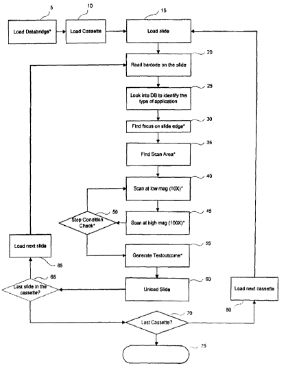
BRIEF DESCRIPTION OF THE DRAWINGS
[0024] Fig. 1 provides a flow chart giving an overview of steps in an
embodiment of the invention.
[0025] Fig. 2 provides a flow chart giving details of steps in an embodiment
of
the invention.
100261 Fig. 3 provides a flow chart giving details of steps in an embodiment
of
the invention.
[0027] Fig. 4 provides a flow chart giving details of steps in an embodiment
of
the invention.
[0028] Fig. 5 provides a flow chart giving details of steps in an embodiment
of
the invention.
[0029] Fig. 6 provides a flow chart giving details of steps in an embodiment
of
the invention.
[0030] Fig. 7 provides a flow chart giving details of steps in an embodiment
of
the invention.
[0031] Fig. 8 provides a flow chart giving details of steps in an embodiment
of
the invention.
[0032] Fig. 9 provides a flow chart giving details of steps in an embodiment
of
the invention.
[0033] Fig. 10 provides a flow chart giving details of steps in an embodiment
of
the invention.
8
CA 02660044 2009-02-03
WO 2008/019324 PCT/US2007/075210
[0034] Fig. 11 provides a flow chart giving details of steps in an embodiment
of
the invention.
100351 Fig. 12 provides a flow chart giving details of steps in an embodiment
of
the invention.
[0036] Fig. 13 provides a flow chart giving details of steps in an embodiment
of
the invention.
DETAILED DESCRIPTION OF THE INVENTION
[0037] Turning to Fig. 1, there is disclosed a master diagrammatic flow chart
of
an embodiment of the present invention. Fig. I presents an overview of the
various
computational modules that together implement the automatic retrieval and
analysis of
samples on multiple slides. Such a collection of slides may arise in a
research setting or in
a diagnostic setting. Large numbers of slides are advantageously examined and
analyzed
by the automated methods disclosed herein. Biological specimens, cellular or
tissue
preparations, and similar subjects of investigation constitute nonlimiting
examples of
subjects for microscopic analysis by methods of the invention. These are
generally termed
"samples" or "specimens" herein. Commonly the samples include labels to assist
in
microscopic analysis. Frequently such labels are fluorescent labels. A sample
may
furthermore include more than one fluorescent labels, wherein each label has
particular
and distinguishable fluorescent properties, esp. distinguishable excitation
and emission
wavelengths. In order to conduct suitable microscopic analysis of such
samples,
appropriate excitation filters are placed in the light beam illuminating the
sample, or one of
a plurality of laser sources of differing wavelengths is chosen, and
corresponding
emission filters are placed between the sample and an image capture device
such as a
camera or charge coupled detector (CCD). In a procedure governing automated
microscopic analysis of such samples, a computer or similar controlling device
must have
available information describing the nature of the probes to be examined.
Sample
identification including this requisite infornlation, as well as additional
sample identifiers,
may be encoded on each slide using an interrogatable coding means, such as a
barcode or
barred array. The interrogatable coding is read as a slide is positioned in
the microscope,
and the corresponding inforrnation is communicated to the computer or
controlling device.
9
CA 02660044 2009-02-03
WO 2008/019324 PCT/US2007/075210
100381 As seen in Fig. 1, the analysis for a particular slide, once loaded in
place
onto the stage of a microscope (15), begins by reading a barcode present on
the slide (20).
The barcode include information designating the nature of the microscopic
analysis to be
carried out. The details for the diverse analytical protocols are stored in a
database for
reference by the computer or controlling device. Once the slide barcode is
read, the
correct experimental protocol is identified in a database (DB) according to
the information
encoded in the barcode (25). With this information now available to control
the operation
of the microscope, a concatenated series of operations that regulate the
focusing, optimize
the region on the slide to be scanned to provide a suitable image, including
adjustments for
low magnification to start with, and moving to a higher magnification for the
actual
analysis, is carried out (see steps 30, 35, 40, 45, and 50). A successful
implementation of
the various modules involved in this protocol provides results, designated a
"Testoutcome"
in Fig. 1 (55). The remaining loops illustrated in Fig. I relate to
determining whether, in a
given cassette, the last slide in the cassette has been examined (65 and 85);
and whether
slides in the last cassette have been analyzed (70 and 80). When the last
cassette has been
examined, the operation of the microscope ceases (75).
[0039] As indicated at Fig. 1, the databridge application is started (step 5)
to run
as a system service for file handling in parallel with other process that may
be running.
Such service may be a method such as shown at Fig. 13, wherein the service is
started
(step 300) which might include setting parameters and the environment in which
the
application will run. In the method of Fig. 13, a configuration file is read
(step 310) such
as may be provided by IKoDataBridge.exe.config (step 305). If preconditions
are not met
an error is recorded in a file, such as an application event log (step 320)
and the process
shut down (step 325). If preconditions are meet (step 315) such as the
existence of source
folders, a loop is performed (step 335) until a shut down is requested.
Starting the loop a
log file is queried for a list of files (step 340), for example ".txt" files.
If files are found
(step 345) another loop is started (step 350) wberein a fiirther check is
performed for a
corresponding file, such as a ".nvc" type file. Existence of the corresponding
file would
then lead to a read of success counts within such a ".nvc" file and cause a
skip of entries in
the original file (step 360). After reading of the entry from the original
file, for example
the ". txt" file (step 365) a query is perfonned as to whether the complete
marker is found
CA 02660044 2009-02-03
WO 2008/019324 PCT/US2007/075210
(step 370), whereupon the text file would be removed (step 375). Interrogation
of more
files is made (step 380), resulting in a return and continuation of the loop
initiated for each
file found, such as a".txt" file (step 350). If more files are not found (step
380) the
system, as illustrated by the alternative path (step 385, 385'), is put to
sleep based on the
time speciffied, for exarriple in a configuration file such as ".config" (step
330).
Completion of the sleep period (step 330) results in return and continuation
of the
shutdown loop starting (step 335). Failure of finding the complete marker in
step 370 will
trigger a specific command in step 425 to execute. If the execution is
successful (step 405)
the reading of an entry from, for example, a ".txt file" is resumed as seen in
step 365. Non
success at step 405 in executing the command of step 425 records an entry into
a log file,
such as an application event log (step 410), query of the error type and count
(step 415)
and possible increment of a retry count at step 430, returning to the
execution step of 425.
A sufficient error or retry count of commands, as tested at step 415 may
result in a
notification to a scanner application as in step 420 and return to step 350
for continue to
loop for another file, such as ".txt" file. In the event a corresponding file,
such as a".nvc"
file does not exist (step 355), a file will be created containing a zero (step
400), where after
the process will occur as performed above continuing from step 365. The
absence of
found files at step 345 would cause a retrieval of a file list from a folder,
for example a
databaselog folder (step 390), and query of the list in step 395 for files. If
no files are
found the service would be placed in sleep mode as shown in step 330, or if
files were
found the process would return to the file loop at step 350.
[00401 Turning back to Fig. I, slides having bar coded or other electronically-
readable indicia are loaded into a cassette (step 10) hav'rrig muitiple slots
from which such
slides may be obtained. A slide for analysis is then loaded (step 15) into an
automated
microscope. The barcode or other electronically-readable indicia is read (step
20) to
detenziine the type of processing demanded (e.g., type of application
demanded) on the
slide by reference to a database (step 25). `I'he automated microscope then
seeks to
execute a number of steps to detect objects of interest in the sample based on
the
processing demand.
100411 First the sample is focused with respect to the objective. Focusing may
be transacted by using a known reference point, such as the slide edge (step
30) from
11
CA 02660044 2009-02-03
WO 2008/019324 PCT/US2007/075210
which focus may be effectuated. Such focusing may be a method such as shown at
Fig. 7
wherein depth of focus in the z range is redefined if certain parameters raise
a flag of out-
of-focus situation (step 11) or not (step 19 termination). In the method
described at Fig. 7,
the slide is exposed to an interrogation for a period of time, for example 100
msec (step
12), with the binning mode being set to cover a substantial area, for example
set to 4X4
(step 13). The interrogation spot is then set to a reference point on the
slide edge, such as
the top middle slide edge (step 14). Autofocus is then performed to determine
a Zbase
(step 16), that is, a base point along the Z axis, such as at the top surface
of the slide edge.
From the Zbase a z-focus upper limit is defined (step 17) , such as 25 times
the depth of
focus from the Zbase, and a z-focus lower limit is defined (step 18)
[0042] Returning to Fig. 1, after focusing, the scan area is determined (step
35)
based upon a predetermined algorithm. For example, Fig. 2 shows two different
schemes
for scan area definition based upon two different FISH-based tests, AneuVysion
(22) and
UroVysion (23) based on bar coded or other electronically-readable indicia on
the slides
(step 21). Such tests differ in the manner of applying the sample, with the
AneuVysion
sample being placed in smear on the slide, and the sample applied to a
UroVysion Slide a
dropped blob.
[0043] As illustrated at Fig. 2, if an AneuVysion test (22) is indicated, the
scanned area is defined at step 24 as being the entire scannable area on the
slide to
determine the position of a smear on the slide. As illustrated, low
magnification field
visits ("survey visits") are made for rapid detection of possible candidates
according to a
sequence along the vertical axis of the slide (step 26), for exanlple, in a
pattern as set forth
at 27. Query of isolated possible candidates may then be perfornied by high
magnification
("investigation mode").
[0044] As fiirther shown in Fig. 2, with respect to UroVysion slide 28
investigation of possible candidate may employ numerous steps. At step 29, a
filter is set
to selectively determine fluorescent signals from a label such as DAPI
interacting with the
sample. Exposure value is set to a predefined value at step 31, and the
binning mode
(merging of distinct pixels) of the camera set to a predefined level, such as
4 x 4 (step 32),
to allow for expeditious scanning of the slide. The Z-motor is then positioned
to allow for
fixed z-position reading of locations on the slide, for- example, set to the
middle of the
12
CA 02660044 2009-02-03
WO 2008/019324 PCT/US2007/075210
entire z-movement range (step 33). Read is made of pre-recorded positions on
the
Urovyision Slide 28, for example, as illustrated 2, 8, 11, and 5 of the
registry (step 34).
Interrogation is made of pre-programmed location field on slide 28, such
location field for
example, encompassing positions 1, 2 and 3 (36), with imaging being made of
the DAPI
signals at such pre-programmed filed and a mean pixel value at each position
being
determined at step 36). At step 37 the position with the largest mean pixel
value (upper
bound) is selected for each pre-programmed location field, as reiterated at
steps 38/39,
41/42 and 43/44. Using the positions identified as having the largest mean
pixel value, a
enclosed boundary is defined (step 46). Within such defined enclosed boundary
there is
ten assigned a low magnification yield visit sequence starting form the center
of the
defined boundary (for example, circle) with the sequence number increasing as
one spirals
out (step 47).
[0045] Turning back to Fig. 1, a low magnification scan is then performed at
step 40. Such low magnification scan may entail discrete steps as set forth at
Fig. 3. At
step 49 magnification is set to a low value, for example, to an objective lens
having lOX
magnification. Quality control measures, such as Objective repeatability, or
other forms of
quality checks may then be determined at step 51, using methodology, for
example, as set
forth at Fig. 5.
[0046] Objective repeatability may be determined using the embodiment
methodology as shown at Fig. 5. First, binning mode is set for each
magnification level
(for example, l OX or 100X as set forth at 139) which will be used to scan the
scan area.
For example, binning mode may be set to 2 x 2 (141 ) or alternatively 4 x 4(
142) as
shown in Fig. 5. With the objective set to the appropriate magnification,
e.g., l OX as set
forth at 143, the interrogation is sent to a predefined position that bas been
determined to
include some features of potential interest 144. Autofocus and autoexposure
are
performed (step 146) with one image grabbed and at least one feature is
identified as, for
example, by determining a gradient, such as an optical gradient (step 147). If
a featLire is
not determined at step 148 the low magnetic field is lowered more and
autofocus and
autoexposure of step 146 is repeated. If a feature is determined at step 148
the
magnification is verified at step 149, features of interest are centered
applying a pre-
defined parfocality offiset (step 152) and the objective magnification
changed, as for
13
CA 02660044 2009-02-03
WO 2008/019324 PCT/US2007/075210
example, to 100X as at step 153. Again, autofocus and autoexposure are
performed (step
154) and a gradient used to find the feature of interest (step 155). A
template may then be
generated around the feature isolated for correlation matching (step 157). The
objective is
then changed once more to the original objective and position, the image is
grabbed and
the offset determined f~oni the previous image based on correlation (step
159). If the
offset is acceptable (step 161) and offset is acceptable multiple consecutive
times, such as,
three times (step 162) the objective repeatability test is terminated (step
164). If
acceptability does not reach offset acceptability in a consecutive
predetermined maximum
number of attempts (step 163) then there is change of the objective back to
the original
position (step 158). If a feature is not found at 148, then there may be a
move down of one
low magnification field (151) and the path continued at step 146.
[0047] Turning back to Fig. 3, after objective repeatability is confirmed at
step
51, an image processing thread is created (step 52). As a simultaneous
process, the image
processing thread is first initialized (step 73), and images saved (step 76)
after waiting for
image processing jobs in the queue (step 74). The images are then processed
and in accord
with an algorithm candidate nuclei are selected and x-y positions of each
candidate nuclei
target are determined (step 77). From the x-y positions determined, the
interrogation
strategy is set based on the high magnification to be used, so as to maximize
the number of
nuclei per field and minimize the total number of high magnification fields
necessary to
visit such nuclei candidates (step 78). A determination is made upon receipt
of images
whether the thread should be terminated (step 79), if not image processing
continues (step
74), and if termination is determined (step 81), then based on the test
screening protocol,
for example, as illustrated, AneaVysior, or UroVysion (step 83), the fields
are sorted in a
manner to provide required information. For example, with respect to an
AneuVysion test
(step 82), the list of high magnification fields may be sorted based on a
number of nuclei
in the filed (step 86), and with respect to a UroVysion test (step 84), the
list of high
magilification fields may be sorted on largest nucleus size in the field (step
87), followed
by termination (step 88).
100481 Now turning to step 53 of Fi.g. 3, after creating the image processing
thread (step 52) as discussed above, the system is set for acquiring images.
First
parameters necessary for imaging are checked, for example, disk space and
activating
14
CA 02660044 2009-02-03
WO 2008/019324 PCT/US2007/075210
source (e.g., lamp). The sample is then visited with a low magnification field
search in the
pre-determined visit sequence order (step 54). In conjunction, filters may be
effectuated,
for example a DAPI filter for determining nuclear tags, and the binning mode
adjusted for
appropriate resolution (step 56). The low magnification objective lens is then
adjusted for
focus (step 57), for exarnple, by a methodology such as described at Fig. 10.
[0049] In Fig. 10, there is shown a method for adjusting low magnification
focus. First there is a determination of whether the low magnification field
is the first low
magnification field in the sequence order (step 232). If the low magnification
field is the
first low magnification field in the sequence order at step 236 the z-range at
the low
magnification field is recalculated by interpolation using database(s)
incorporating z-focus
range found from the "find focus on slide edge" (233) and z-difference from
the top edge
to bottom edge (234) if possible if not (step 237) there is tennination (step
186). If the low
magnification field is not the first low magnification field in the sequence
order, then the
neighborhood of potential structures of interest is set to a defined number
(step 239) and
each neighborhood is inquired in low magnification (step 241) to determine if
there is one
or more neighborhoods with a valid z focus value (step 244), and if so, the
average of all
the z focus values is taken (step 247), and if not, the number or size of
neighborhoods are
expanded (step 243) until there are no more neighbors to expand (243), and a
flag (237) is
sent to complete (186) the string.
[0050] Returning back to Fig. 3, at step 58 autofocus and autoexposure are
performed The binning mode may then be cbanged (step 59), for example, to I x
1 as
illustrated, an image, for example a DAPI image (step 71), acquired. Depending
on the
test used to elucidate objects of interest, such as, for example, an
Aneuvyision test (72),
one may need to alter other microscopic parameters to elucidate such objects.
For
exaniple, there may be need to alter filtering (step 61) of emanating signals
from the
sample, and change the exposure value of the sample (step 62). Once an image
is acquired
(step 63) it may be proeessed using the processing thread discussed supra
(step 64) and
once all candidates are located (step 66), and each of the fields interrogated
(step 67), the imaging process thread is terminated (step 81).
[0051] Depending upon the test protocol used (e.g., AneuVysion or LUroVysion
82, 83, 84), the processed images are handled in a predetermined manner, for
example,
CA 02660044 2009-02-03
WO 2008/019324 PCT/US2007/075210
with respect to an AneuVysion test by sorting the list of high magnification
fields based on
the number of nuclei in a field (step 86) and with respect to a UroVysion
test, sorting the
list of high magnification fields on the basis of the largest nucleus size in
the field (step
87). If all candidates are not located (step 66), and each of the fields is
not interrogated
(step 67), and the scan area rnay be redefined (steps 68, 69).
[0052] Redefinition of the scanner area may be by the methodology of Fig. 8
wherein a central point is selected from which spiral seanning techniques such
as in the
order set forth in Fig. 14 are performed. Such spiral scanning may be defined
by the
equation of step 181. In such methodology, at step 179 , obtain the number of
nuclei, Ny,
in each field scanned along the vertical central line. At step 182, calculate
the y-coordinate
of the center, Cy, using weighted average. Subsequently at step 183, calculate
the x-
coordinate, Cx, where the vertical central axis of the slide lies. Then at
step 184, define
the scanning area centered around (Cx, Cy) with its diameter about the width
of the slide.
Finally at step 185, before termination (step 187), assign scanning sequence
number for
each low mag field inside the circle. Sequence number starts from the center
of the area
and increases as it spirals out. It should skip the area which was scanned
already.
[0053] Once the low magnification scan area is defined (step 35 of Fig. 1) and
the sample is scanned at low magnification (step 40 of Fig. 1), a scan at high
magnification
may be performed (step 45 of Fig. 1).
[0054] High magnification scanning may employ a methodology such as
portrayed at Fig. 4. The objective is set to high magnification, and camera
gain set to
highest gain (step 89). The imaging processing thread for high magnification
is then
created (step 91) by first initialization (step 129), waiting for irtiage
processing jobs in the
queue (step 131), saving the image (step 132), processing image stacks (step
133) (such as
DAPI and FISH images), updating the high magnification field probability map
(step 134),
classifying the targets of interest (step 136), e.g., nuclei, and finally
ending the thread if
appropriate (steps 137/124) and continuing at 126. The updating of tlie high
rnagnification
field probability map of step 134 may be by a method as set forth in the flow
chart set forth
at Fig. 12.
[0055] As shown, at step 300, there is provided input as to the probability
that a
object (such as a DAPI object) has other objects of interest associated (such
as FISH
16
CA 02660044 2009-02-03
WO 2008/019324 PCT/US2007/075210
objects) and input pertaining to the number of objects for each high
magnification field.
Next there is calculation of the expected value of the number of signals of
interest having
other objects of interest associated therewith (step 305) such as DAPI objects
having Fish
Signals, in each high magnification field. The high magnification fields are
then sorted
(step 310) according to the nurn'oer of usefui objects, such as DAPI objects.
(step 310), the
high magnification fields with the largest number of useful objects, such as
DAPI objects,
are scanned and the probability of usefiil objects, such as DAPI objects, for
the low
magnification fields are adjusted (step 315). The expected valve of the number
of objects
having a desired signal (e.g. DAPI objects having FISH signals) in each of the
high
magnification fields are calculated at step 320.
[0056] For example, the high magnification field probability map with respect
to DAPI objects having FISH signals may be determined. DAPI objects for high
magnification scanning may be sorted based on the number of objects contained
in the
high magnification field in order to reduce the number of fields to be scanned
to find
enough useful DAPI objects within the least amount of time. DAPI objects
having good
FISH signals (i.e. objects containing the most number of useful DAPI objects)
may be
further sorted to reduce the time necessary of high magnification analysis.
Assuming the
probability for a high magnification field being properly processed to have
FISH objects to
be p = m/n, every time a DAPI object is found to contain FISH objects, the
probability can
be addressed to be p=(m+1)/(n-t-1). Every time a DAPI object is found to
contain FISH
objects, adjust the probability to be p=rn/(n+1). The expected value of the
number of
useful objects in each high magnification field is then the multiplication of
the number of
DAPI objects and the probability. The high niagtiification field wiin the
largest expected
value of the number of objects may be cbosen to be scanned. Note that, the
value of p can
be obtained statistically by experiments on typical slides. With a fixed p,
the value of rn (or
n) needs to be care.fully chosen so that each object, no matter it has FISH
signals or not,
can have a proper impact factor on the probability adjustment.
[0057] The pseudo code of an algorithm for a DAPFFISH system that may be
used is set forth below:
I. Let the initial lowmag field quality indicator be pi=rrt,iti;=p=m/fa.
17
CA 02660044 2009-02-03
WO 2008/019324 PCT/US2007/075210
2. Calculate the expected value of the number of objects in each himag field
and sort them.
3. Choose the himag field with the largest expected number of objects.
4. If the expected number of objects is less than Nmi,,, stop.
5. Scan and analyze the himag ieid chosen.
6. For each object in the himag field, decide if it contains FISH signals. Let
n;= n; +1. If the object contains FISH signals, then mi= mi +1.
7. If enough useful DAPI objects have been found, stop.
8. Calculate the new field quality indicator p;=inilni.
9. tJpdate the expected value of the number of objects based on the field
quality indicator in the remaining himag fields within the current lowmag
field.
10. Sort the remaining himag fields and go to 3.
[0058] By choosing appropriate values from In and n, one can achieve a large
variety of scanning strategies. For high magnification scanning application,
it may be desired that the algorithm be able to abandon the field where there
are objects without
FISH signals. To do so, one may choose small values for m and n (for example,
in = 1, n=
2; or if one wants to abandon fields faster, m = 0.5, n = 1). The N,,,ij, may
be chosen, for
example, to = 0.2 - 0.3.
[00591 In respect of the classification of nuclei at step 136, classification
may be
directed by the particular testing protocol being employed, such as, for
example,
AneuVysioniUroVysion (209, 211, 212) of Fig. 11. For example, when nuclei on a
AneuVysion test slide are being counted, a simplc determination of whether tl-
ie dot count
in any of the FISH channels does not contain a countable flag (step 213) may
be used to
determine whether the proposed nuclei dot should be counted (216) or not
counted (214).
Similarly, when miclei on an UroVysion test slide are being counted, channel
count may
be used in respect to classification of the nuclei. For example, if two or
more channels in a
plurality of channels, for example three channels, have more than two dots
(217), then an
abnormal classification (223) may be given, or the first three channels have
two dots and
the last (e.g. gold) channels has zero dots (219), a classification of
abnoimal (226) may be
given, while if the first three channels have two dots and the last (e.g.,
gold) chamrel has
18
CA 02660044 2009-02-03
WO 2008/019324 PCT/US2007/075210
two dots (221), then a classification of normal (227) may ensue. If only one
channel in the
first of the plurality of channels has more than two dots (218) then the
classification may
be singlegain (224), while if at least two channels in the first three
channels has more than
one dot and zero dot in gold (222), then a classification of zerogold (228) or
unclassified
(229) may be rendered. Uj,o-ri classification of each nuclei the
classification process may
be tenninated (231).
[0060] A scan at high magnification (step 45 of Fig. 1) employing the
methodology as set forth at Fig. 4, after creation of the image processing
thread (step 91)
may transact an object repeatability test (92), for example, as discussed with
respect to Fig.
supra. Again parameters of the microscope such as disk space and lamp (step
93) may
be performed and the stop condition checked (94).
[0061] Stop condition checking (94) may depend on the particular testing
protocol being employed, for example, AneuVysion or LJroVysion (166, 167, 168;
see Fig.
6).
100621 If AneuVysion (167), for example, a determination may be made if the
total scanning area has been scanned (169) and if it is so having the stop
condition being
set (173) and the process terminated (174). On the other hand, if a
detennination is made
that the total scanning area has not been made (169), then the total nuclei
collected at high
magnification may be compared to a threshold, such as equal to or greater than
500 (171).
If this threshold has been met, the stop condition may be determined to be met
(173). If
the threshold has not been found to be met, and the highest nuclei number in
all the cell
categories is determined to be above a predetermined minimum threshold (such
as equal to
or greater than 50) (172), the stop condition may also be detei-mined to have
beeri met
(173). If it is below the predetermined minimum threshold, the stop condition
may be
determined not to have been met (176).
[0063] If UroVysion is the particular protocol employed (168), a determination
may be made if the total scamiing area bas been scamled (177), and if so the
stop condition
being met, and if not another parameter being sued to meet the stop condition
(173). For
example, one might make as a condition of a stop condition being met (173)
that the total
nuclei collected at high magnification be equal to or greater than the value
the user
specified (178) (if not the stop condition is not met 176).
19
CA 02660044 2009-02-03
WO 2008/019324 PCT/US2007/075210
[0064] Turning back to Fig 4, the type of test performed on the sample (for
example, AneuVysion (step 96)) may influence the step of high magnification
scanning
(step 45 of Fig. 1). For example, if AneuVysion is the test (step 96) one
might choose the
high magnification field with the next highest expected number of nuclei (step
138) for
scanning, while if such test was r~ot employed, the next high magnification
field in the list
(step 97) might be scanned. It may be necessary in the process to periodically
adjust
parameters of the microscope, for example, resenting the lamp timer at every
50th high
magnification field (step 98). Before taking an image it is advantageous to
confirm that
the image processing queue is available (step 99). Appropriate filters (step
102) may need
to be set, the shutter set to on (step 103) and the high magnification field
entered (step
101). The exposure time to an appropriate interrogation wavelength may then be
estimated with a setting of a binning mode (step 104). After adjusting
autoexposure and
autofocus (step 106), an image, such as a DAPI image, may be taken at the
focus position
and the exposure values found (step 107). Parcentricity should be eonfirmed by
determining parcentricity offset (step 108) and if the offset is too much
(step 109) the
objective turned between low and high magnification (step 127), the check
process
repeated, or if there is a determination that the last high magnification
field has been
reached (step 123) the image processing thread terminated (step 124). If the
offset is not
too much, then other mask may be employed, such as a DAPI mask and the
parcentricity
offset updated (step 111). After requiring a stack of images, for example nine
slices, the
best focused plane may be determined (step 112), further filters set (step
113), such as a
filter for detecting FISH signals, and exposure time recalculated and binning
mode set
(step 114). Autoexposure on the best focused plane may be effected (step 116)
foilowed
by resetting of the binning mode to a new value and applying exposure (step
117) to obtain
a stack of images of the signals to which the filter has been set (step 118),
for example
FISH signals, until the desired number of filters to produce the stack has
been completed
(step 119). The shutter of the image obtaining device may then be set to off
(step 121), the
images obtained sent to the image processing thread (step 122) with the image
processing
thread being terminated (step 124) after determining the last high
magnification field has
been queried (step 123), Finishing of the high magnification scan (step 126)
upon a stop
CA 02660044 2009-02-03
WO 2008/019324 PCT/US2007/075210
condition check (step 50 of Fig. 1) - such as described above with respect to
Fig. 6, may
prompt the automated microscope to generate a testoutcome (step 55 of Fig. 1).
[0065] A exemplary automated method for determining a testoutcome (step 55
of Fig. 1) with respect to a Aneuvyision or UroVysion test (188, 189, 191) is
set forth at
Fig. 9. As depicted with respect to a AneuVysion test (189) each fluorescent
taggant (CEP
v. LSI) (192) is analyzed with respect to binding with the target chromosomal
regions for
such taggants. For example, with respect to CEP (193) the X, Y and 18
dotcounts are
determined (step 196), and with respect to LSI (194) the dotcounts with
respect to
chromosomes 13 and 21 are obtained (step 197). The dotcounts determined are
then
matched (step 198) against a database of possible outcomes for CEP labeling
(201) or LSI
labeling (202). If the dotcount obtained matches a possible dotcount outcome
for valid
CEP labeling (201) then the output matched is sent as the testoutcome. However
if the
dotcount obtained does not match with a possible dotcount outcome for valid
CEP labeling
(201), then there is a determination if the reason for the failure of the
match is due to the
analysis of too few nuclei (step 199), and if yes the testoutcome output is
sent as "less
than 50 nuclei images" (206), and if no the testoutcome is output as "review
recommended" (204). Testoutcome is terminated at 208.
[0066] Turning back to Fig. 1, after generation of a testoutcome (step 55),
the
slide having been interrogated is unloaded (step 60) and a new slide from the
cassette is
loaded (step 85) if the slide is not the last slide in the cassette (steps 65,
70). If it is the
last slide in the cassette (step 70) then the next cassette may be loaded if
such is available
(step 80), or if not the run may be terminated (step 75).
STATEMENT REGARDING PREFERRED EMBODIMENTS
[0067] While the invention has been described with respect to preferred
embodiments, those skilled in the art will readily appreciate that various
changes andl`or
modifications can be made to the invention without departing from the spirit
or scope of
the invention as defined by the appended claims. All documents cited herein
are
incorporated by reference herein where appropriate for teachings of additional
or
alternative details, features and/or technical background.
21