Note: Descriptions are shown in the official language in which they were submitted.
CA 02660118 2009-02-05
WO 2008/033527 PCT/US2007/020046
Housing for Inductive Coupler for Power Line Communications
BACKGROUND OF THE INVENTION
1. Field of the Invention
[0001] The present invention relates to power line communications, and, more
particularly, to a
configuration of a data coupler for power line communications.
2. Description of the Related Art
[0002] Power line communications (PLC), also known as broadband over power
line (BPL), is a
technology that encompasses transmission of data at high frequencies through
existing electric
power lines, i.e., conductors used for carrying a power current. A data
coupler for PLC couples a
data signal between a power line and a communication device such as a modem.
[0003] An example of such a data coupler is an inductive coupler that includes
a core, and a
winding wound around a portion of the core. The inductive coupler operates as
a transformer,
where the core is situated on a power line such that the power.line serves as
a primary winding of
the transformer, and the winding of the inductive coupler is a secondary
winding of the
transformer.
10004] The core is typically constructed of a magnetic material, such as a
ferrite, a powdered
metal, or a nano-crystalline material. The core is electrified by contact with
the power line and
requires insulation from the secondary winding. Typically, the core and the
secondary winding
are insulated by embedding both the core and the secondary winding in
electrically insulating
material, such as silicone.
[0005] At times, an electric utility lineman may be required to install an
inductive coupler on an
energized medium such as a high voltage power line. As such, the inductive
coupler is required
to meet safety requirements, to avoid injury to personnel performing
installation, maintenance or
removal thereof.
SUMMARY OF THE INVENTION
1
CA 02660118 2009-02-05
WO 2008/033527 PCT/US2007/020046
[0006] There is provided an inductive coupler. The inductive coupler includes
(a) a housing
having an aperture that extends lengthwise through the housing, a gap that
extends lengthwise
along a side of the housing, and a flexible region that enables the gap to be
opened or closed.
The gap, when opened, permits the inductive coupler to be installed on a
conductor by having the
conductor routed through the aperture. The inductive coupler also includes (b)
a magnetic core;
and (c) a winding wound around a portion of the magnetic core. The magnetic
core and the
winding are secured to the housing such that a position of the magnetic core
and a position of the
winding are maintained relative to one another. The inductive coupler, when
installed on the
conductor, couples a signal between the conductor and the winding via the
magnetic core.
BRIEF DESCRIPTION OF THE DRAWINGS
[0007] FIG. I is a three-dimensional view of an inductive coupler, in an open
position.
[0008] FIG. 1 A is a three-dimensional view of the inductive coupler of FIG. 1
in a partially
closed position.
[0009] FIG. 1 B is a three-dimensional view of the inductive coupler of FIG. I
in a fully closed
position.
[0010] FIG. 2 is a cross-sectional view of the inductive coupler of FIG. 1.
[0011] FIG. 3 is a three-dimensional view of an inductive coupler, in a
partially open position,
situated around power lines.
[0012] FIG. 4 is a three-dimensional view of an inductive coupler equipped
with rubber bands.
[0013] FIG. 4A is a three-dimensional view of the inductive coupler of FIG. 4
in a closed
position, on a power line.
[0014] FIG. 5 is a three-dimensional view of an inductive coupler in an open
position.
[0015] FIG. 6 is a three-dimensional view of an inductive coupler and a hot
stick, situated
adjacent to a power line.
2
CA 02660118 2009-02-05
WO 2008/033527 PCT/US2007/020046
[0016] FIG. 6A is a three-dimensional view of the inductive coupler of FIG. 6,
being held open
by the hot stick.
[0017] FIG. 6B is a three-dimensional view of the inductive coupler of FIG. 6,
in a partially
opened position, situated on the power line.
[0018] FIG. 6C is a three-dimensional view of the inductive coupler of FIG. 6,
in a closed
position, situated on the power line.
[0019] FIG. 7 is a three-dimensional view of an inductive coupler.
DESCRIPTION OF THE INVENTION
[0020] In a PLC system, power current is typically transmitted through a power
line at a
frequency in the range of 50-60 hertz (Hz). In a low voltage line, power
current is transmitted
with a voltage between about 90 to 600 volts, and in a medium voltage line,
power current is
transmitted with a voltage between about 2,400 volts to 35,000 volts. The
frequency of the data
signals is greater than or equal to about 1 megahertz (MHz), and the voltage
of the data signal
ranges from a fraction of a volt to a few tens of volts.
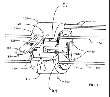
[0021] FIG. 1 is a three-dimensional view of an inductive coupler 100 in an
open position,
situated for installation on power lines 150 and 155. Inductive coupler 100
includes a housing
105 that is of a one piece, uni-body construction. Housing 105 is fabricated
of a hard plastic
material, an elastic material, or a resilient material. An elastic material is
capable of partially or
fully returning to its original length or shape after being stretched or
deforined. The elastic
material preferably has an elongation of about 10% to about 900% utilizing
test method ASTM
D 1456-86, Standard Test Method For Rubber Property-Elongation at Specific
Stress. A resilient
material absorbs energy when it is deformed elastically and then, upon
unloading, recoverably
releases that energy.
[0022] Housing 105 includes an aperture 103 that runs lengthwise through
housing 105. Power
lines 150 and 155 are routed through aperture 103. Housing 105 also includes a
magnetic core
200 (shown in FIG. 2), and a winding 145 that is wrapped around magnetic core
200. Winding
145 protrudes from housing 105 and connects to other electronic equipment (not
shown) within a
3
CA 02660118 2009-02-05
WO 2008/033527 PCT/US2007/020046
PLC system. Inductive coupler 100 operates as a transformer, where, for
example, power line
150 is a first winding, and winding 145 is a second winding, and couples a
signal between power
line 150 and winding 145 via magnetic core 200.
[0023] Housing 105 has a gap 108 (represented by a dashed line) that extends
lengthwise along a
side of housing 105. Gap 108 is situated between a face 107 and a face 109.
Housing 105 has a
flexible region 130 that allows for faces 107 and 109 to be (a) separated
apart frorn one another,
thus opening gap 108, or (b) brought toward one another, thus closing gap 108.
Thus, flexible
region 130 functions similarly to a hinge. In FIG. 1, gap 108 is shown in an
opened position.
100241 Housing 105 includes a strap 115 and a=protrusion 110. Strap 115 is
attached to housing
105 at a junetion 129, and has a hole 120, a notch 125, and a notch 127. Strap
115 can be
configured as either an integral part of housing 105, or a non-integral part
that is attached to
housing 105 at junction 129. Housing 105 also has an end face with a pair of
flanges, i.e.,
flanges 135. A cable tie 140 (two of which are shown in FIG. 1) is seated on
flanges 135. The
significance of strap 115, hole 120, notch 125, notch 127, protrusion 110,
flanges 135 and cable
tie 140 is described below, with reference to FIGS. lA and 1B.
[0025] FIG. 1 A is a three-dimensional view of inductive coupler 100 in a
partial ly-closed
position. Strap 115 is bent toward protrusion 110 to effect engagement of
notch 125 and
protrusion 110. Cable tie 140 is self-engaged, and forms a perimeter that
encompasses flanges
135. If cable tie 140 is tightened, the perimeter will be reduced, thus
drawing flanges 135 toward
one another.
[00261 FIG. 1 B is a three-dimensional view of inductive coupler 100 in a
fully closed
configuration, installed on power lines 150 and 155. Cable tie 140 has been
tensioned to effect
closure of housing 105. Strap 115 has been bent to effect engagement of notch
127 and
protrusion 110. The tension in cable tie 140 provides additional support for
bundling power lines
150 and 155 together.
[0027] FIG. 2 is a cross-sectional view of inductive coupler 100 in its open
position. As
mentioned earlier, inductive coupler 100 includes magnetic core 200. Magnetic
core 200 is
configured of a core section 200A and a core section 200B. Flexible region 130
allows for core
halves 200A and 200B to be moved relative to one another. Configuring magnetic
core 200 as
4
CA 02660118 2009-02-05
WO 2008/033527 PCT/US2007/020046
two sections, i.e., core section 200A and core section 200B, facilitates a
placement of inductive
coupler 100 on power line 150. Core section 200A, core section 200B, and a
looped portion of
winding 145 are enclosed by housing 105. As such, housing 105 maintains a
spatial relationship
between winding 145, core section 200A and core section 200B. That is,
magnetic core 200 and
winding 145 are secured to housing 105 such that a position of magnetic core
200 and a position
of winding 145 are maintained relative to one another.
[0028] To install inductive coupler 100 onto power lines 150 and 155, or to
remove inductive
coupler 100 from power lines 150 and 155, a lineman may use a long insulated
tool typically
termed a "hot stick." The hot stick has a hook that engages hole 120, to allow
the lineman to
move strap 115 so that notch 125 or notch 127 either engages protrusion 1 10,
or disengages from
protrusion 110.
100291 Although FIGS. 1, lA, 1B, and 2 show inductive coupler 100 in the
context of an
installation on two power lines, i.e. power lines 150 and 155, inductive
coupler 100 can be
installed on a single power line, and, more generally, one or more power
lines.
[0030] In review, inductive coupler 100 includes housing 105, magnetic core
200, and winding
145. Aperture 103 extends lengthwise through housing 105, and gap 108 extends
lengthwise
along a side of housing 105 between faces 107 and 109. Flexible region 130
enables gap 108 to
be opened or closed. Flexible region 130 may be, e.g., a hinge. Gap 108, when
opened, permits
inductive coupler 100 to be installed on a conductor routed through aperture
103. Winding 145
is wound around a portion of magnetic core 200. Further, magnetic core 200 and
winding 145
are secured in such a way to housing 105 as to maintain a position relative to
each other. When
inductive coupler 100 is installed on a conductor, it couples a signal between
the conductor and
winding 145, via magnetic core 200.
[0031] FIG. 3 is a three-dimensional view of an inductive coupler 300, in a
partially open
position, situated around a power line 350 and a power line 355. Inductive
coupler 300 includes
a housing 305 having an aperture 303 that extends lengthwise through housing
305. Inductive
coupler 300 also includes magnetic core 200 (not shown in FIG. 3) and winding
145 (not shown
in FIG. 3). Power lines 350 and 355 are routed through aperture 303. Winding
145 is wrapped
around a portion of magnetic core 200. Leads 345 from winding 145 protrude
from housing 305
and connect to components of a PLC system (not shown).
CA 02660118 2009-02-05
WO 2008/033527 PCT/US2007/020046
[0032] Housing 105 is of a one piece, uni-body construction, and is fabricated
of a hard plastic
material, an elastic material, or a resilient material. Housing 305 provides
structural support for
magnetic core 200. Housing 305 also has a flexible region 330, a strap 315, a
protrusion 310,
and flanges 335. Strap 315 extends from housing 305, attached thereto at a
junction 329. Strap
315 has a hole 320 and a notch 325. Protrusion 310 and notch 325 are
configured to engage one
another. A user can obtain a grip on strap 315 at hole 320, and, by pulling
thereon, cause strap
315 to flex about junction 329, and thereby effect engageinent of notch 325
and protrusion 310,
to secure inductive coupler 300 in a closed configuration.
[0033] Flanges 335 each include apertures 337. One cable tie 340 is routed
through the apertures
337 in one of flanges 335, and another cable tie 340 is routed through the
apertures in another
one of flanges 335, to secure power lines 350 and 355 and inductive coupler
300 to one another.
[0034] Although FIG. 3 shows inductive coupler 300 installed on two power
lines, i.e. power
lines 350 and 355, with cable tie 340 fastened around power lines 350 and 355,
inductive coupler
300 can be installed on a single power line, and, more generally, one or more
power lines, with
cable tie 340 being fastened around the one or more power lines.
[0035] FIG. 4 is a three-dimensional view of an inductive coupler 400.
Inductive coupler 400 is
similar to inductive coupler 300 in that inductive coupler 400 includes a
housing 405, a strap
415, a notch 425, a protrusion 410 and flanges 435. Housing 405 is of a one
piece, uni-body
construction, and is fabricated of a hard plastic material, an elastic
material, or a resilient
material. Differently from inductiye coupler 300, inductive coupler 400
includes a rubber band
440 (two of which are shown in FIG. 4). Rubber band 440 encompasses flanges
435 within a
perimeter. When a power line 450 exerts contact forces on rubber band 440, the
resulting tension
in rubber band 440 causes a reduction in the perimeter, so that flanges 435
are drawn toward one
another.
[0036] FIG. 4A is a three-dimensional view of inductive coupler 400 in a
closed position about
power line 450. Rubber band 440 is asserting tension against power line 450,
and protrusion 410
is engaging notch 425.
[0037] FIG. 5 is a three-dimensional view of an inductive coupler 500 in an
open configuration,
adjacent to a power line 550. Inductive coupler 500 has a housing 505 that
includes an aperture
6
CA 02660118 2009-02-05
WO 2008/033527 PCT/US2007/020046
503 that runs lengthwise through housing 505, a gap 508 (represented by a
dashed line) that
extends lengthwise along a side of housing 505, and a flexible region 530.
Housing 505 is of a
one piece, uni-body construction, and is fabricated of a hard plastic
material, an elastic material,
or a resilient material. Inductive coupler 500 is similar to inductive coupler
400 except that
instead of using a rubber band 440 around flanges 435, inductive coupler 500
uses an actuator
540 (two of which are shown in FIG. 5). Actuator 540 is an integral actuating
structure, i.e., an
integral part of housing 505. A design with non-integral actuators is also
possible. That is, an
actuator that is not an integral part of housing 505, for example, a rubber
band.
[0038] Actuator 540 bridges gap 508. When power line 550 is pushed against
actuator 540,
toward aperture 503, actuator 540 moves away from gap 508. Housing 505 flexes
about flexible
region 530, and contact forces between power line 550 and actuator 540 effect
a closure of
aperture 503 and gap 508.
[0039] FIG. 6 is a three-dimensional view of an inductive coupler 600 and a
hot stick 660,
situated adjacent to a power line 650. Inductive coupler 600 includes a
housing 605 that has an
aperture 603 that runs lengthwise through housing 605. Housing 605 is of a one
piece, uni-body
construction, and is fabricated of a hard plastic material, an elastic
material, or a resilient
material. Housing 605 includes a protrusion 610, and a strap 615 having a hole
620 and a notch
625. Housing 605 also includes nubs 642, a strap 652, a strap 652A and a strap
652B. Strap
652A connects strap 652 to a top portion of housing 605. Strap 652B connects
strap 652 to a
bottom portion of housing 605. Strap 652 has a hole 653.
[0040] Hot stick 660 includes a hook 665, a hinge 667, a housing 670, and
teeth 675. In FIG. 6,
hook 665 is shown in an open position, and is routed through hole 653. Hook
665 can be
retracted into housing 670, thus forcing hook 665 to close.
[0041] FIG. 6A is a three-dimensional view of inductive coupler 600 engaged by
hot stick 660 so
that inductive coupler 600 is held open. Tn FIG. 6A, as compared to FIG. 6,
hook 665 has been
retracted into housing 670, thereby forcing straps 652A and 652B into closer
proximity to one
another. Housing 605 has a flexible region 630. Since straps 652A and 652B are
forced into
closer proximity to one another, housing 605 is opened about flexible region
630. With housing
605 thus opened, power line 650 can be introduced into aperture 603.
7
CA 02660118 2009-02-05
WO 2008/033527 PCT/US2007/020046
[0042] FIG. 6B is a three-dimensional view of inductive coupler 600 in an
almost closed
position, situated on power line 650. Inductive coupler 600 and hot stick 660,
and their
respective parts, are as depicted in FIG. 6, except that in FIG. 6B, hook 665
is engaging strap 615
through hole 620, and inductive coupler 600 is mostly closed around power line
650. A user may
strap 615 downward to effect engagement of hole 620 and protrusion 610.
[00431 FIG. 6C is a three-dimensional view of inductive coupler 600 in a
closed position on
power line 650. Inductive coupler 600 and hot stick 660, and their respective
parts, are as
depicted in FIG. 6A, except that in FIG. 6C, a user has effected engagement of
notch 625 and
protrusion 610, thereby securely installing inductive coup] er 600 on power
line 650.
[0044] In FIG. 6C, teeth 675 are interlocking with nubs 642. This interlocking
allows for
housing 670 to produce an opposing force after hook 665 is looped through hole
620 (see FIG.
6B) and retracted into housing 670. While strap 615 is pulled down into
housing 670, notch 625
seats over protrusion 610 to provide a positive closing of coupler 600 around
power line 650.
[0045] Inductive coupler 600 has a magnetic core, similar to magnetic core
200, embedded
within housing 605. When inductive coupler 600 is closed about, i.e. installed
on, power line
650, housing 605 maintains a position of power line 650 and a position of the
magetic core
relative to one another.
[0046] FIG. 7 is a three-dimensional view of an inductive coupler 700 in an
open position, in
-close proximity to a power line 750. Inductive coupler 700 includes a housing
705, a magnetic
core 753, and a winding 745.
[0047] Housing 705 is of a one piece, uni-body construction, and is fabricated
of an elastic
material. Housing 705 has a flexible region 730, a protrusion 710, and a strap
715 that has a hole
720 and a notch 725. Housing 705 also has an aperture 703 that extends
lengthwise through
housing 705.
10048] Magnetic core 753 is configured of a core section 753A and a core
section 753B.
Winding 745 is wound around core section 753A. Magnetic core 753 is not
completely
embedded in housing 705, but instead, has an exposed surface that faces
aperture 703. Winding
745 is not embedded in housing 705. Generally, for each of inductive couplers
100, 300, 400,
8
CA 02660118 2009-02-05
WO 2008/033527 PCT/US2007/020046
500 and 600, neither of the magnetic core nor the winding needs to be fully
embedded within the
housing, but instead, could be exposed in a manner similar to that of magnetic
core 753 and
winding 745.
j00491 Housing 705 also includes an actuator 740. Actuator 740 allows for core
section 753A
and core section 753B to be pulled away from one another, thus increasing the
size of aperture
703. Inductive coupler 700 is then positioned around power line 750.
Iiiitially, external forces
are applied to inductive coupler 700 via, gloved hands or hot stick (not
shown), to hold inductive
coupler 700 open. Once these forces are removed, actuator 740 contracts to
loosely close
inductive coupler 700 onto power line 750. Hole 720 can thereafter be engaged
by a hook, so
that strap 715 can be pulled down to effect an engagement of notch 725 and
protrusion 710, thus
establishing a positive closure of inductive coupler 700 around power line
750.
9