Note: Descriptions are shown in the official language in which they were submitted.
t A CA 02660400 2009-02-09
WO 2008/017552 PCT/EP20071056919
1
System, reactor and process for the continuous industrial production of poly-
etheralkylalkoxysilanes
The present invention relates to a new reactor and a system for the continuous
industrial production of polyetheralkylalkoxysilanes by reaction of an a,(3-
unsaturated
aliphatic polyether compound with an HSi compound, and also to a corresponding
process.
Organosilanes, such as vinylchlorosilanes and vinylalkoxysilanes (EP 0 456 901
Al,
EP 0 806 427 A2), chloroalkylchlorosilanes (DE-B 28 15 316, EP 0 519 181 Al,
DE 195 34 853 Al, EP 0 823 434 Al, EP 1 020 473 A2), alkylalkoxysilanes
(EP 0 714 901 Al, DE 101 52 284 Al), fluoroalkylalkoxysilanes (EP 0 838 467
Al,
DE 103 01 997 Al), aminoalkylaikoxysilanes (DE-A 27 53 124, EP 0 709 391 A2,
EP 0 849 271 A2, EP 1 209 162 A2, EP 1 295 889 A2),
glycidyloxyalkylalkoxysilanes
(EP 1 070 721 A2, EP 0 934 947 A2), methacryloyloxyalkylalkoxysilanes
(EP 0 707 009 Al, EP 0 708 081 A2), polyetheralkylalkoxysilanes (EP 0 387 689
A2),
and many more, are of high technical and industrial interest. Processes and
systems for
their production are well established. These products are comparatively low-
tonnage
products and are produced predominantly in batch processes. Generally this is
done
using systems which can be used many times, in order to maximize the degree of
capacity utilization of the batch systems. When there is a changeover of
product,
however, extensive cleaning and rinsing operations are necessary on such batch
systems. Furthermore, in many cases, long residence times of the reaction
mixture in a
high-volume, expensive, and labour-intensive batch system are necessary in
order to
obtain a sufficient yield. Furthermore, said reactions are often considerably
exothermic,
with heats of reaction in the range from 100 to 180 kJ/mol. In the course of
the reaction,
therefore, it is also possible for unwanted secondary reactions to have a
considerable
influence on selectivity and yield. Where said reactions are hydrosilylations,
the possible
elimination of hydrogen poses considerable challenges for the safety
engineering.
Frequently, furthermore, in a semibatch procedure, a reactant is introduced
together
with the catalyst, and the other reactant is metered in. Furthermore, even
small
fluctuations in the process regime of batch or semibatch systems can lead to a
CA 02660400 2009-02-09
WO 2008/017552 PCT/EP2007/056919
2
considerable scafter of the yields and product qualities over different
batches. If the aim
is to scale up results from the laboratory/pilot-plant scale to the batch
scale, it is also not
uncommon for difficulties to occur.
Microstructured reactions per se, for the purpose for example of continuous
production
of polyether alcohols (DE 10 2004 013 551 Al) or the synthesis of products
including
ammonia, methanol, and MTBE (WO 03/078052), are known. Also known are
microreactors for catalytic reactions (WO 01/54807). To date, however, the
microreactor
technology has been omitted for the industrial production of organosilanes, or
at least
not realized. The tendency of alkoxysilanes and chlorosilanes to undergo
hydrolysis - in
the case even of small amounts of moisture - and corresponding instances of
wall
deposits in an organosilane production system, are likely seen as a persistent
problem.
The object was therefore to provide a further possibility for the industrial
production of
polyetheralkylalkoxysilanes. A particular concern was to provide a further
possibility for
the continuous production of such organosilanes, the aim being to minimize the
disadvantages identified above.
The object proposed is achieved in accordance with the invention in accordance
with
the details in the claims.
In the case of the present invention it has surprisingly been found that the
hydrosilylation of an HSi-containing component B, more particularly a
hydrogenalkoxysilane, with an a,(3-unsaturated aliphatic polyether compound
(component A) can be carried out advantageously in the presence of a catalyst
C, in a
simple and economic way on an industrial scale and continuously, in a system
based on
a multielement reactor (5), the multielement reactor (5) more particularly
comprising at
least two reactor units in the form of replaceable preliminary reactors (5.1)
and at least
one further reactor unit (5.3) downstream of the preliminary reactors.
Advantageously, therefore, through the use of a multielement reactor (5) in
the present
embodiment, it is possible to contribute to the continuous operation of the
operation
CA 02660400 2009-02-09
WO 2008/017552 PCT/EP2007/056919
3
according to the invention, since the present multielement reactor (5) permits
the
deliberate replacement, in rotation, of preliminary reactors in which, after a
period of
operation, significant amounts of hydrolyzate are deposited, by fresh
preliminary
reactors, even under operating conditions.
In this context it is possible in a particularly advantageous way to use
preliminary
reactors which are furnished with packing elements, thereby making it possible
even
more deliberately and effectively to obtain deposition of hydrolyzate or
hydrolyzate
particles and hence a reduction in the tendency toward clogging and downtimes
of the
system as a result of floor and wall deposits in the reactor.
In contradistinction to what is the case with a batch approach, it is possible
in the case
of the present invention to carry out continuous premixing of the reactants
immediately
ahead of the multielement reactor; the premixing may also take place cold,
with
subsequent heating in the multielement reactor for purposive and continuous
reaction
therein. It is also possible to add a catalyst to the reactant mixture.
Subsequently the
product can be worked up continuously, as for example in an evaporation or
rectification
procedure and/or in a short-path or thin-film evaporator - to name just a few
possibilities.
In the multielement reactor, the heat of reaction that is liberated during the
reaction can
be taken off advantageously via the surface area of the internal reactor
walls, which is
large in relation to the reactor volume, and, where provided, to a heat
transfer medium.
Furthermore, in the case of the present application of multielement reactors,
it is
possible to achieve a significant increase in the space/time yield of rapid,
exothermic
reactions. This is made possible by more rapid mixing of the reactants, a
higher average
concentration level of the reactants than in the case of the batch process,
i.e., no
limitation as a result of reactant depletion, and/or an increase in the
temperature, which
in general is able to produce an additional acceleration of the reaction.
Furthermore, in
a comparatively simple and economic way, the present invention permits
operational
safety to be preserved. Thus it has been possible in the case of the present
invention to
achieve a drastic intensification of operation, more particularly a shortening
of the
operating time under reaction conditions by more than 99%, based on the
space/time
yield, in comparison to the standard batch process. At the same time,
increased yields
CA 02660400 2009-02-09
WO 2008/017552 PCT/EP2007/056919
4
of up to 20% have been achieved as a result of higher conversions and
selectivities.
The present reactions were carried out with preference in a stainless steel
multielement
reactor. In this way it is possible, with advantage, to do without the use of
specialty
materials for the implementation of said reactions. In addition it is
possible, as a result of
the continuous operation in reactions that are to be carried out under
pressure, to
observe a longer service life of the metal reactors, since the material
suffers fatigue
much more slowly than in a batch procedure. Moreover, distinct improvements
have
been achieved in reproducibility in relation to comparable investigations in
the case of
batch processes. In addition, in the case of the present process, there is a
significantly
reduced scale-up risk when the results from the laboratory scale or pilot-
plant scale are
transposed. More particularly, in the case of the present continuous process
utilizing a
system according to the invention, where a multielement reactor advantageously
comprises at least one replaceable preliminary reactor, packed preferably with
packing
elements, it is possible to permit a surprisingly long running time of the
system, even
without downtime caused by floor and wall deposits. Furthermore, in a
surprising way, it
has been found that in the case of the present process it is particularly
advantageous to
rinse the multielement reactor, prior to the start of the reaction proper,
with the reaction
mixture, more particularly when said mixture comprises a homogeneous catalyst;
in
other words, to carry out preconditioning of the multielement reactor. As a
result of this
measure it is possible to produce an unexpectedly rapid coming-about of
consistent
operating conditions at a high level.
The present invention accordingly provides a system for the continuous
industrial
implementation of a reaction, an a,f3-unsaturated aliphatic polyether compound
A being
reacted with an HSi compound B in the presence of a catalyst C and optionally
of
further auxiliaries, and the system being based at least on the reactant
combiner (3) for
components A (1) and B (2), on at least one multielement reactor (5), which in
turn
comprises at least two reactor units in the form of at least one replaceable
preliminary
reactor (5.1) and at least one further reactor unit (5.3), downstream of the
preliminary
reactor system, and on a product workup unit (8).
The present invention further provides a multielement reactor (5) for the
reaction of
CA 02660400 2009-02-09
WO 2008/017552 PCT/EP2007/056919
hydrolyzable silanes, more particularly of those which contain HSi units,
which in turn
comprises at least two reactor units in the form of at least one replaceable
preliminary
reactor (5.1) and at least one further reactor unit (5.3) downstream of the
preliminary
reactor system.
5
Preference is given here to preliminary reactors (5.1) which are equipped with
packing
elements. Suitable packing elements for this purpose include for example - but
not
exclusively - structured packing elements, i.e., regular or irregular
particles of identical
or different size, preferably with an average particle size, the average
particle diameter
of the cross-sectional area being <_ 1/3, more preferably 1/10 to 1/100, of
the free cross
section of the respective reactor unit (5.1), and also the average particle
cross-sectional
area being preferably 100 to 10-6 mm2, such as chips, fibers/wool, beads,
shards,
strands with a circular or approximately circular or polygonal cross section,
spirals,
cylinders, tubes, cups, saddles, honeycombs, plates, meshes, wovens, open-
pored
sponges, irregular shaped and hollow articles, (structured) packings or bound
assemblies of aforementioned structural elements, etc., spherical elements of
metal,
metal oxide, ceramic, glass or plastic (such as steel, stainless steel,
titanium, copper,
aluminum, titanium oxides, aluminum oxides, corundum, silicon oxides, quartz,
silicates,
clays, zeolites, alkali glass, boron glass, quartz glass, porous ceramic,
vitreous ceramic,
specialty ceramic, SiC, Si3N4, BN, SiBNC, ... and many more.
Figures 1 to 6 show flow diagrams of systems or system parts as preferred
embodiments of the present invention.
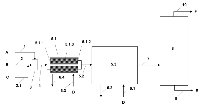
Thus, figure 1 shows a preferred continuous system in which the reactant
components
A and B are brought together in the unit (3), supplied to the unit (5), which
may contain
an immobilized catalyst, and reacted therein, and the reaction product is
worked up in
the unit (8).
Figure 2 shows a further preferred embodiment of a present continuous system,
a
catalyst C being supplied to component B. The catalyst, more particularly a
homogeneous catalyst, may alternatively be supplied to unit (3) or - as
apparent from
CA 02660400 2009-02-09
WO 2008/017552 PCT/EP2007/056919
6
figure 3 - the catalyst C may be metered into a mixture of components A and B
shortly
prior to entry into the multielement reactor unit (5).
Furthermore, further auxiliaries may optionally be added to each of the
aforementioned
streams.
By a reactor unit in this context is meant an element of the multielement
reactor (5),
each element representing a region or reaction chamber for the stated
reaction; cf., for
example, (5.1) (reactor unit in the form of a preliminary reactor) in figure 4
and also (5.5)
[reactor unit of an integrated block reactor (5.3.1)] in figure 5, and also
(5.10) [reactor
unit of a micro-tube bundle heat exchanger reactor (5.9)]. Therefore, reactor
units of a
multielement reactor (5) for the purposes of the present invention are more
particularly
stainless-steel or quartz-glass capillaries, stainless-steel tubes or well-
dimensioned
stainless-steel reactors, examples being preliminary reactors (5.1), tubes
(5.10) in
micro-tube bundle heat exchanger reactors [e.g., (5.9)] and also regions (5.5)
delimited
by walls, in the form of integrated block reactors [e.g., (5.3.1)]. The
internal walls of the
reactor elements may be coated, with, for example, a ceramic layer, a layer of
metal
oxides, such as A1203, Ti02, Si02, Zr02, zeolites, silicates, to name but a
few, although
organic polymers, more particularly fluoropolymers, such as Teflon, are also
possible.
Accordingly a system of the invention comprises one or more multielement
reactors (5)
which in turn are based on at least 2 up to 1 000 000 reactor units, including
all of the
natural numbers situated in between, preferably from 3 to 10 000, more
particularly from
4 to 1000 reactor units.
The reactor chamber or reaction chamber of at least one reactor unit
preferably has a
semicircular, semioval, circular, oval, triangular, square, rectangular or
trapezoidal cross
section normal to the direction of flow. Such a cross section preferably
possesses a
cross-sectional area of 75 pm2 to 75 cm2. Particular preference is given to
cross-
sectional areas of 0.7 to 120 mm2 and all numerical values situated
numerically in
between. In the case of circular cross-sectional areas, a diameter of >_ 30 pm
to
< 15 mm, more particularly 150 pm to 10 mm, is preferred. Polygonal cross-
sectional
CA 02660400 2009-02-09
WO 2008/017552 PCT/EP2007/056919
7
areas have edge lengths preferably of _ 30 pm to < 15 mm, preferably 0.1 to 12
mm. In
one multielement reactor (5) of a system of the invention there may be reactor
units
having different-shaped cross-sectional areas.
Furthermore, the structure length in a reactor unit, i.e., from entry point of
the reaction
stream or product stream into the reactor unit, cf. e.g. (5.1 and 5.1.1) or
(5.5 and 5.5.1),
to the exit point, cf. (5.1.2) or (5.5.2), is preferably 5 cm to 500 m,
including all numerical
values situated numerically in between, more preferably >_ 15 cm to 100 m,
very
preferably 20 cm to 50 m, more particularly 25 cm to 30 m.
In a system of the invention preference is given to reactor units whose
respective
reaction volume (also referred to as reactor volume, i.e., the product of
cross-sectional
area and structure length) is 0.01 ml to 100 I, including all numerical values
situated
numerically in between. With particular preference the reactor volume of one
reactor
unit of a system of the invention is 0.05 ml to 10 I, very preferably 1 ml to
5 I, very
preferably 3 ml to 2 I, more particularly 5 ml to 500 ml.
In addition it is possible to base systems of the invention on one or more
multielement
reactors (5), which are preferably connected in parallel. Alternatively said
multielement
reactors (5) can be connected in series, and so the product coming from the
upstream
multielement reactor can be supplied to the inlet of the downstream
multielement
reactor.
Present multielement reactors (5) can be fed advantageously with a reactant
component
stream (4) or (5.2), suitably divided into the respective substreams, cf. e.g.
(5.4) in
figure 5 and also (5.11) in figure 6. Following the reaction, the product
streams can be
brought together, cf. e.g. (5.7) in figure 5, (5.12) in figure 6 and also (7),
and then
advantageously worked up in a workup unit (8). A workup unit (8) of this kind
may to
start with have a condensation stage or evaporation stage, which is followed
by one or
more distillation stages.
Furthermore, a multielement reactor (5) of a system of the invention may be
based on at
least one, preferably at least two, stainless-steel capillaries connected in
parallel, or on
CA 02660400 2009-02-09
WO 2008/017552 PCT/EP2007/056919
8
at least two quartz-glass capillaries connected in parallel, or on at least
one tube-bundle
heat exchanger reactor (5.9) or on at least one integrated block reactor
(5.3.1).
In this context it is possible more particularly to use stainless-steel
capillaries, reactors,
and preliminary reactors, which are composed advantageously of a high-
strength, high-
temperature-resistant, and nonrusting stainless steel; by way of example, but
not
exclusively, preliminary reactors, capillaries, block reactors, tube bundle
heat exchanger
reactors, etc., are composed of steel of grade 1.4571 or 1.4462, cf. more
particularly
also steel according to DIN 17007. Furthermore, the surface of a stainless-
steel
capillary or of a multielement reactor that faces the reaction chamber may be
furnished
with a polymer layer, such as a fluorine-containing layer, Teflon inter alia,
or with a
ceramic layer, preferably a nonporous or porous Si02, Ti02 or AI203 layer,
intended
more particularly for the accommodation of a catalyst.
More particularly it is possible with advantage to use an integrated block
reactor, of the
kind apparent, for example, as a temperature-controllable block reactor,
constructed
from metal plates with defined structuring (also called planes below), from
http://www.heatric.com/pche-construction.html.
The production of said structured metal plates or planes from which a block
reactor can
then be produced may take place, for example, by etching, turning, cutting,
milling,
embossing, rolling, spark erosion, laser machining, plasma technique or
another
technique of the machining methods known per se. In this way, with an
extremely high
level of precision, well-defined and targetedly arranged structures, such as
grooves or
joints, are incorporated on one side of a metal plate, more particularly a
metal plate
made of stainless steel. The respective grooves or joints begin at one end
face of the
metal plate, are continuous, and end generally at the opposite end face of the
metal
plate.
Thus figure 5 shows one plane of an integrated block reactor (5.3.1) having a
plurality of
reactor units or elements (5.5). A plane of this kind is composed generally of
a metal
base plate with metal walls (5.6) thereon that delimit the reaction chambers
(5.5),
CA 02660400 2009-02-09
WO 2008/017552 PCT/EP2007/056919
9
together with a metal top plate, and also with a temperature control unit
(6.5, 6.6),
preferably with a further plane or structured metal plate. The unit (5.3.1)
further
comprises a region (5.4) for the input and distribution of the reactant
mixture (5.2) into
the reactor elements (5.5), and a region (5.7) for the bringing-together of
the product
streams from the reaction regions (5.5) and discharge of the product stream
(7).
Furthermore, as part of an integrated block reactor (5.3.1), there may also be
two or
more such above-described planes connected one above another. The connection
may
be carried out, for example, by (diffusion) welding or soldering; on such
working
techniques and others which can be employed here cf. also www.imm-
mainz.de/seiten/de/u_050527115034_2679.php?PHPSESSID=75a6285eb0433122b9c
ecaca3092dadb. Furthermore, integrated block reactors (5.3.1) of this kind are
advantageously surrounded by a temperature control unit (6.5, 6.6) which
allows the
heating or cooling of the block reactor (5.3.1), i.e., a targeted temperature
control
regime. For this purpose a medium (D), e.g., Marlotherm or Mediatherm, may be
brought to the desired temperature by means of a heat exchanger (6.7) and
supplied via
line (6.8) to a pump (6.9) and line (6.1) to the temperature control unit
(6.5), and
discharged via (6.6) and (6.2), and supplied to the heat exchanger unit (6.7).
Heat of
reaction released in an integrated block reactor (5.3.1) can be controlled
optimally in a
very short path, thereby making it possible to avoid temperature spikes with
an adverse
effect on a controlled reaction regime. Alternatively the integrated block
reactor (5.3.1)
and the associated temperature control unit (6.5, 6.6) may also be configured
such that
there is a temperature control plane arranged between each two reactor element
planes, said temperature control plane permitting an even more directed
control of the
thermal conditioning medium between the regions (6.1, 6.5) and (6.6, 6.2).
In systems of the invention preference is given more particularly to a
multielement
reactor (5) which comprises at least one preliminary reactor (5.1) and at
least one
further reactor unit (5.3), a stainless-steel capillary for example, or at
least one
preliminary reactor (5.1) and at least one integrated block reactor (5.3.1) or
at least one
preliminary reactor (5.1) and at least one micro-tube bundle heat exchanger
reactor
(5.9); cf. figure 4. Furthermore, the preliminary reactor (5.1) is designed so
as to be
suitably temperature-controllable, i.e., coolable and/or heatable (D, 6.3,
6.4).
CA 02660400 2009-02-09
WO 2008/017552 PCT/EP2007/056919
In general, even traces of water lead to the hydrolysis of the alkoxysilane or
chlorosilane
reactants and hence to instances of floor or wall deposits. The particular
advantage of
such an embodiment of a preliminary reactor (5.1) in the context of the
multielement
5 reactor (5), more particularly for the reaction of silanes, is that, in
addition to the
continuous reaction carried out through deliberate deposition and removal of
hydrolyzates or particles, it is possible advantageously to minimize unplanned
idle times
and downtime. Hence the preliminary reactors (5.1) equipped in accordance with
the
invention may additionally be fitted, upstream and/or downstream, with filters
for particle
10 deposition.
Generally speaking, a system of the invention for the continuous industrial
implementation of reactions is based on a reactant combiner (3) for components
A and
B, on at least one said multielement reactor (5), and on a product workup unit
(8), cf.
figures 1, 2, and 3, the multielement reactor (5) comprising at least two
reactor units in
the form of replaceable preliminary reactors (5.1), which are preferably
equipped with
packing elements, and at least one further reactor unit (5.3) downstream of
the
preliminary reactor system.
The reactant components A and B may each be brought deliberately together,
continuously, in the region (3) from a reservoir unit by means of pumps and,
optionally,
by means of a differential weighing system. Generally speaking, components A
and B
are metered, and mixed in the region (3), at ambient temperature, preferably
at 10 to
40 C. Alternatively at least one of the components, both components or
ingredients, or
the corresponding mixture may also be preheated. Hence said reservoir unit may
be
brought to temperature, and the reservoir vessels may also be of temperature-
controllable design. Furthermore, the reactant components may be brought
together
under pressure. The reactant mixture can be supplied continuously to the
multielement
reactor (5) via line (4).
The multielement reactor (5) is preferably brought to and held at the desired
operating
temperature by means of a temperature control medium D (6.1, 6.2), so that
unwanted
CA 02660400 2009-02-09
WO 2008/017552 PCT/EP2007/056919
11
temperature spikes and temperature fluctuations, as known from batch plants,
can be
advantageously prevented or sufficiently minimized in the case of the present
system of
the invention.
The product stream or crude-product stream (7) is supplied continuously to the
product
workup unit (8), a rectifying unit for example, in which case a low-boiling
product F, as
for example silane which is used in excess and is optimally recyclable, can be
taken off
continuously, for example, via the top (10), while via the bottom (9) a higher-
boiling
product E can be taken off continuously. It is also possible, however, to take
off side
streams as a product from the unit (8).
If it is necessary to have to carry out the reaction of components A and B in
the
presence of a catalyst C, then it is possible, advantageously, to insert a
homogeneous
catalyst into the reactant stream by metering. An alternative option is to use
a
suspension catalyst, which can likewise be metered into the reactant stream.
In this
case the maximum particle diameter of the suspension catalyst ought
advantageously to
amount to less than 1/3 of the extent of the smallest free cross-sectional
area of a
reactor unit of the multielement reactor (5).
Thus figure 2 shows that a said catalyst C is advantageously metered into
component
B, before the latter is brought together with component A in the region (3).
A homogeneous catalyst C or a suspension catalyst C may alternatively be
metered into
a mixture of A and B, which is conducted in line (4), preferably shortly prior
to entry into
the multielement reactor, via a line (2.2); cf. figure 3.
In the same way as in the case of a homogeneous catalyst, the reactant
components A
and B may also be admixed with further, predominantly liquid auxiliaries, such
as, for
example - but not exclusively - activators, initiators, stabilizers,
inhibitors, solvents,
diluents, etc.
Another possibility, however, is to choose a multielement reactor (5) which is
equipped
with an immobilized catalyst C; cf. figure 1. The catalyst C may be present
for example -
CA 02660400 2009-02-09
WO 2008/017552 PCT/EP2007/056919
12
but not exclusively - at the surface of the reaction chamber of the respective
reactor
elements.
Generally speaking, a system of the invention for the continuous industrial
implementation of the reaction of a said compound A with a compound B,
optionally in
the presence of a catalyst and also further auxiliaries, is based on at least
one reactant
combiner (3), at least one multielement reactor (5), which in turn comprises
at least two
reactor units of the invention, and on a product workup unit (8). Suitably the
reactants or
ingredients are provided in a reservoir unit for the implementation of the
reaction, and
are supplied or metered as required. Furthermore, a system of the invention is
equipped
with the measuring, metering, blocking, transporting, conveying, monitoring,
and control
units, and also offgas and waste processing apparatus, that are customary per
se in the
art. In addition, a system of the invention of this kind may advantageously be
accommodated in a transportable and stackable container, and made flexible.
Thus a
system of the invention may be brought rapidly and flexibly, for example, to
the
particular reactant or energy sources required. With a system of the
invention, however,
it is also possible to provide product continuously with all of the
advantages, more
specifically at the site at which the product is further-processed or further-
used, as for
example directly at customers' premises.
A further advantage, deserving particular emphasis, of a system of the
invention for the
continuous industrial implementation of a reaction of a,R-unsaturated
compounds A with
an HSi compound B is that a facility is now also available for preparing small
specialty
products, with volumes of between 5 kg and 100 000 t p. a., preferably 10 kg
to
10 000 t p. a., continuously and flexibly in a simple and economic way.
Unnecessary
idle times, temperature spikes and temperature fluctuations effecting the
yield and
selectivity, and also excessively long residence times and hence unwanted side
reactions can be advantageously avoided. In particular it is also possible to
utilize such
a system optimally for the preparation of present silanes from economic,
environmental,
and customer convenience standpoints.
The present invention accordingly further provides a process for the
continuous
CA 02660400 2009-02-09
WO 2008/017552 PCT/EP2007/056919
13
industrial production of a polyetheralkylalkoxysilane of the general formula
(I)
Y-Si(R`)m(OR)s-m (I),
in which Y is a polyetheralkyl group of the form H3C[O-(CH2)2]õO-(CH2)3- with
n = 1 to 20 or H[O-(CH2)2]nO-(CH2)3- with n = 1 to 20, R' and R independently
are
a C, to C4 alkyl group, preferably methyl, ethyl, n-propyl, and m is 0 or 1,
the reaction of the reactant components A and B in the presence of a catalyst
C and
also optionally of further components being carried out in a multielement
reactor (5)
which in turn is based on at least two reactor units in the form of at least
one
replaceable preliminary reactor (5.1) and at least one further reactor unit
(5.3)
downstream of the preliminary reactor system.
This reaction is preferably carried out in at least one multielement reactor
(5) whose
reactor units are composed of stainless steel or quartz glass or whose
reaction
chambers are delimited by stainless steel or quartz glass, it being possible
for the
surfaces of the reactor units to have been coated or lined, with Teflon, for
example.
In processes according to the invention it is preferred, furthermore, to use
reactor units
whose respective cross section is semicircular, semioval, circular, oval,
triangular,
square, rectangular or trapezoidal.
Use is made advantageously in this context of reactor units whose respective
cross-
sectional area is 75 pm2 to 75 cm2.
Furthermore, the reactor units used preferably are those which have a
structure length
of 5 cm to 200 m, more preferably 10 cm to 120 m, very preferably 15 cm to 80
m, more
particularly 18 cm to 30 m, including all possible numerical values which are
included by
the ranges stated above.
Thus use is suitably made, in the process according to the invention, of
reactor units
CA 02660400 2009-02-09
WO 2008/017552 PCT/EP2007/056919
14
whose respective reaction volume is 0.01 ml to 100 1, including all numerical
values
situated numerically in between, preferably 0.1 ml to 50 I, more preferably 1
ml to 20 I,
very preferably 2 ml to 10 I, more particularly 5 ml to 5 I.
In the case of the process of the invention it is likewise possible
advantageously to carry
out the said reaction in a system with a multielement reactor (5) which is
based (i) on at
least two preliminary reactors (5.1) connected in parallel and on at least one
stainiess-
steel capillary downstream of the preliminary reactors, or (ii) on at least
two preliminary
reactors (5.1) connected in parallel and on at least one quartz-glass
capillary
downstream of the preliminary reactors, or (iii) on at least two preliminary
reactors (5.1)
connected in parallel and on at least one integrated block reactor (5.3.1), or
(iv) on at
least two preliminary reactors (5.1) connected in parallel and on at least one
tube-
bundle heat exchanger reactor (5.9).
Particular preference is given in this context to a multielement reactor (5)
which
comprises at least two replaceable preliminary reactors (5.1) according to the
invention,
said preliminary reactors being furnished with packing elements, of the kind
set out
more particularly above, for the purpose of depositing hydrolysis products of
hydrolyzable silanes that are used. With particular preference the method of
the
invention is carried out in reactor units made of stainless steel.
A further preference is for the surface of the reactor units of the
multielement reactor
that is in contact with the reactant/product mixture to be lined with a
catalyst in the
process according to the invention.
Where, as part of the process of the invention, the reaction of components A
and B is
carried out in the presence of a homogeneous catalyst C, it has surprisingly
been found
that it is particularly advantageous to carry out preconditioning of the
multielement
reactor by means of one or more flushes with a mixture of homogeneous catalyst
C and
component B, or of homogeneous catalyst C and components A and B, or short-
term
operation of the system, for 10 to 120 minutes, for example, and optionally
with a
relatively high catalyst concentration.
CA 02660400 2009-02-09
WO 2008/017552 PCT/EP2007/056919
The materials used for the preconditioning of the multielement reactor may be
collected
and later on metered in again, at least proportionally, to the reactant stream
or supplied
directly to the product workup unit and worked up.
5 By virtue of the preconditioning of the multielement reactor as described
above, more
particularly when said reactor is composed of stainless steel, it is possible,
in a
surprising and advantageous way, to obtain a constant operating state with
maximum
yield more quickly.
10 In the context of the process of the invention, the stated reaction can be
carried out in
the gas and/or liquid phase. The reaction mixture and/or product mixture may
be a
single-phase, two-phase or three-phase mixture. With the method of the
invention the
reaction is preferably carried out in single-phase form, more particularly in
the liquid
phase.
Hence the process of the invention is operated advantageously using a
multielement
reactor at a temperature of 10 to 250 C under a pressure of 0.1 to 500 bar
abs.
Preferably the reaction of components A and B, more particularly a
hydrosilylation, is
carried out in the multielement reactor at a temperature of 50 to 200 C,
preferably at 60
to 180 C, and at a pressure of 0.5 to 300 bar abs, preferably at 1 to 200 bar
abs, more
preferably at 2 to 50 bar abs.
In general the pressure difference in a system of the invention, i.e., between
reactant
combiner (3) and product workup unit (8), is 1 to 10 bar abs. It is possible
with
advantage to equip a system of the invention with a pressure maintenance
valve,
especially when using trimethoxysilane (TMOS). The pressure maintenance valve
is set
preferably at from 1 to 100 bar abs, more preferably up to 70 bar abs, with
particular
preference up to 40 bar abs, more particularly to a value between 10 to 35 bar
abs.
The reaction can be carried out in accordance with the invention at a linear
velocity (LV)
of 1 to 1. 104 h-' (stp). The flow rate of the stream of material in the
reactor units is
preferably in the range from 0.0001 to 1 m/s (stp), more preferably 0.0005 to
0.7 m/s,
CA 02660400 2009-02-09
WO 2008/017552 PCT/EP20071056919
16
more particularly 0.05 to 0.3 m/s, and all possible numbers within the
aforementioned
ranges. If the ratio of reactor surface (A) prevailing in the case of
inventive reaction is
related to the reactor volume (V), then preference is given to an A/V ratio of
20 to
5000 m2/m3 - including all numerically possible individual values which lie
within the
stated range - for the advantageous implementation of the process of the
invention. The
A/V ratio is a measure of the heat transfer and also of possible heterogeneous
(wall)
effects.
Thus the reaction in processes of the invention is carried out advantageously
with an
average residence time (.& ) of 10 seconds to 60 minutes, preferably 1 to 30
minutes,
more preferably 2 to 20 minutes, more particularly 3 to 10 minutes. Here
again, specific
reference is to all possible numerical values disclosed by the stated range.
As component A it is possible in the process of the invention to make use for
example -
but not exclusively - of the following a,f3-unsaturated polyether compounds or
corresponding mixtures thereof:
H3C[O-(CH2)2]õO-CH2CH=CH2 with n = 1 to 20, more particularly the numbers 2,
3, 4, 5,
6, 7, 8, 9, 10, 11, 12, 13, 14, 15, 16, 17, 18, and 19, H[O-(CH2)2]õO-
CH2CH=CH2 with
n = 1 to 20, more particularly 2, 3, 4, 5, 6, 7, 8, 9, 10, 11, 12, 13, 14, 15,
16, 17, 18, and
19.
The process of the invention is used preferably to prepare Dynasylan 4140,
3-(methylpolyethylene glycol)propyltrialkoxysilane, corresponding to the
general formula
(I) with m = 0 and with n = 2 to 20, more preferably 4 to 18, very preferably
6 to 16,
more particularly with 8 to 12, i.e., on average around 10.
Suitable components B in the process of the invention are silanes of the
general formula
(II)
HSi(R')m(OR)3-m (II),
CA 02660400 2009-02-09
WO 2008/017552 PCT/EP2007/056919
17
in which R' and R independently are a C, to C4 alkyl group and m is 0 or 1,
preferably R' being methyl and group R preferably being methyl or ethyl.
Hence in accordance with the invention it is preferred to use trimethoxysilane
(TMOS),
triethoxysilane (TEOS), methyldimethoxysilane or methyidiethoxysilane.
In the process of the invention the components A and B are used preferably in
a molar
ratio of A to B of 1:5 to 100:1, more preferably 1:4 to 5:1, very preferably
1:2 to 2:1, for
example - but not exclusively - 1:0.7 to 0.9, more particularly from 1.0:1.5
to 1.5:1.0,
including all possible numbers within the aforementioned ranges.
The process of the invention is carried out preferably in the presence of a
homogeneous
catalyst C. However, the process of the invention can also be operated without
the
addition of a catalyst, in which case, generally, a distinct drop in yield is
likely.
The process of the invention is utilized more particularly for the
implementation of a
hydrosilylation reaction for the preparation of organosilanes of formula (I),
with, more
particularly, homogeneous catalysts from the series of Pt complex catalysts,
such as
those of the Karstedt type, for example, such as Pt(0)-
divinyltetramethyldisiloxane in
xylene, PtCl4, H2[PtCI6] or H2[PtCl6] - 6H2O, preferably a "Speyer catalyst",
cis-
(Ph3P)2PtCI2, complex catalysts of Pd, Rh, Ru, Cu, Ag, Au, Ir or those of
other transition
metals and/or noble metals. The complex catalysts known per se may be
dissolved in
an organic solvent, preferably a polar solvent, for example - but not
exclusively - ethers,
such as THF, ketones, such as acetone, alcohols, such as isopropanol,
aliphatic or
aromatic hydrocarbons, such as toluene, xylene.
Additionally the homogeneous catalyst or the solution of the homogeneous
catalyst may
be admixed with an activator, in the form for example of an organic or
inorganic acid,
such as HCI, H2SO4, H3PO4, monocarboxylic and/or dicarboxylic acids, HCOOH,
H3C-COOH, propionic acid, oxalic acid, succinic acid, citric acid, benzoic
acid, phthalic
acid - to name but a few.
CA 02660400 2009-02-09
WO 2008/017552 PCT/EP2007/056919
18
Furthermore, the addition of an organic or inorganic acid to the reaction
mixture may
take on another advantageous function, for example as a stabilizer or
inhibitor for
impurities in the trace range.
Where a homogeneous catalyst or a suspension catalyst is used in the process
of the
invention, the olefin component A is used relative to the catalyst, based on
the metal,
preferably in a molar ratio of 2 000 000:1 to 1000:1, more preferably of 1 000
000:1 to
4000:1, more particularly of 500 000:1 to 10 000:1, and all possible numerical
values
within the ranges stated above.
It is also possible, however, to use an immobilized catalyst or heterogeneous
catalyst
from the series of the transition metals and/or noble metals, and/or a
corresponding
multielement catalyst, for carrying out the hydrosilylation reaction. Thus it
is possible for
example - but not exclusively - to use noble metal slurries or noble metal on
activated
carbon. An alternative is to provide a fixed bed for the accommodation of a
heterogeneous catalyst in the region of the multielement reactor. Thus, for
example -
but not exclusively - it is also possible to incorporate heterogeneous
catalysts, on a
support, such as beads, strands, pellets, cylinders, stirrers, etc., of Si02,
Ti02, AI203,
Zr02, among others, into the reaction region of the reactor units.
Examples of integrated block reactors with a fixed catalyst bed are given at
http://www. heatric.com/iqs/sid.0833095090382426307150/mab_reactors. html.
As auxiliaries it is possible, furthermore, to use solvents and diluents, such
as alcohols,
aliphatic and aromatic hydrocarbons, ethers, esters, ketones, CHC, FCHC - to
name
but a few. Such auxiliaries may be removed from the product, for example, in
the
product workup unit.
In the case of the present process it is likewise possible to use inhibitors,
examples
being polymerization inhibitors or corresponding mixtures, as additional
auxiliaries.
CA 02660400 2009-02-09
WO 2008/017552 PCT/EP2007/056919
19
The process of the invention is generally carried out as follows:
In general the reactant components A, B, and, if appropriate, C, and also any
further
auxiliaries, are first metered in and mixed. The aim here is to meter a
homogeneous
catalyst with an accuracy of <_ 20%, preferably <_ 10%. In particular
cases the
homogeneous catalyst and also, optionally, further auxiliaries may also only
be metered
into the mixture of components A and B shortly before entry into the
multielement
reactor. Subsequently the reactant mixture can be supplied to the multielement
reactor,
and the components reacted, with the temperature being monitored. An
alternative is
first to flush or precondition the multielement reactor with a catalyst-
containing reactant
or reactant mixture, before running up the temperature in order to carry out
the reaction.
The preconditioning of the multielement reactor can alternatively be carried
out at a
slightly elevated temperature. The product streams brought together or
obtained in the
multielement reactor (crude product) can thereafter be worked up appropriately
in a
product workup unit of the system of the invention, by means for example - but
not
exclusively - of a vacuum distillation facility, in which case stripping
agents may also be
used. The method is preferably operated continuously.
Thus the process of the invention can be operated continuously using a system
of the
invention, in an advantageous way, with a product discharge of 5 kg to 100 000
t p. a.
The present invention is illustrated by the following example, without the
subject matter
being restricted.
Examples
Example 1
Preparation of 3-(methyl polyethylene glycol)propyltrimethoxysi lane
The system used for the continuous preparation of 3-(methylpolyethylene
glycol)propyl-
trimethoxysilane (Dynasylan 4140) consisted essentially of the reactant
reservoir
vessels, HPLC pumps, control, measurement, and metering units, a T mixer, four
replaceable stainless steel preliminary reactors, connected in series and
packed with
CA 02660400 2009-02-09
WO 2008/017552 PCT/EP2007/056919
packing elements (the reactors each being as follows: diameter 10 mm, length
50 mm,
stainless steel beads with on average 1.5 mm diameter as packing elements), an
integrated stainless steel block reactor - cf. also figure 5 on this point -,
temperature
regulation, a pressure maintenance valve, a stripping column operated with N2,
and
5 connecting lines in the system for reactant supply, between the
abovementioned system
components and also product discharge, recycling takeoff, and offgas removal.
Furthermore, thermal conditioning was provided via a heating and cooling
system for the
preliminary reactors and for the block reactor.
10 First of all, at room temperature, the polyetherolefin (ZALP 500,
Goldschmidt) and an
acetonic, HOAc-containing solution of hexachloroplatinic acid in a molar
olefin:Pt ratio of
48 000:1 and a molar olefin:acetic acid ratio of 1:0.01 were metered and mixed
and this
mixture was mixed in the T mixer with trimethoxysilane (TMOS, Degussa AG) in a
molar
olefin:TMOS ratio of 1:0.85, and supplied to the reactor system. The pressure
was
15 25 10 bar. When the system is being run up, the aim ought to be for a
very highly
H20-free condition of the system. Furthermore, before the temperature in the
reactor
was raised, the system was flushed with reactant mixture for 2 hours. At a
throughput
totalling 10 kg/h, the temperature in the reactors was raised, set at 110 C
and operated
continuously over 27 days. According to reactor, samples for GC-WLD
measurements
20 were taken at intervals of time. The conversion, based on the olefin, was
97% on
average and the selectivity, based on the target product, was 75%. The crude
product
obtained was passed continuously into the stripping column and stripped
continuously
at a jacket temperature of 150 C, p = 20 mbar, with N2 (volume flow = 100 I/h,
T = 150 C). The top product was condensed and consisted of around 4% by weight
of
acetone, 5% by weight of acetic acid, 78% by weight of TMOS, 11 % by weight of
tetramethoxysilane and 2% by weight of methanol. From the bottom a figure of
around
9.8 kg/h of hydrosilylation product (Dynasylan 4140) were taken off
continuously.
Example 2
Preparation of 3-(methylpolyethylene glycol)propyltrimethoxysilane
For the continuous preparation of 3-(methylpolyethylene
glycol)propyltrimethoxysilane
CA 02660400 2009-02-09
WO 2008/017552 PCT/EP2007/056919
21
(Dynasylan 4140), a system according to example 1 was used.
First of all, at room temperature, the polyetherolefin (ZALP 500, Goldschmidt)
and a
xylene-containing solution of the Pt(0) complex catalyst (CPC072, Degussa) in
a molar
olefin:Pt ratio of 48 000:1 and a molar olefin:propionic acid ratio of 1:0.01
were metered
and mixed and this mixture was mixed in the T mixer with trimethoxysilane
(TMOS,
Degussa AG) in a molar olefin:TMOS ratio of 1:0.85, and supplied to the
reactor
system. The pressure was 25 10 bar. When the system is being run up, the aim
ought
to be for a very highly H20-free condition of the system. Furthermore, before
the
temperature in the reactor was raised, the system was flushed with reactant
mixture for
2 hours. At a throughput totaling 10 kg/h, the temperature in the reactors was
raised, set
at 130 C and operated continuously over 10 days. According to reactor, samples
for
GC-WLD measurements were taken at intervals of time. The conversion, based on
the
olefin, was 97% on average and the selectivity, based on the target product,
was 80%.
The crude product obtained was passed continuously into the stripping column
and
stripped continuously at a jacket temperature of 150 C, p = 200 mbar, with N2
(volume
flow = 100 I/h, T= 150 C). The top product was condensed and consisted of 9%
by
weight of propionic acid, 80% by weight of TMOS, 10% by weight of
tetramethoxysilane
and 1% by weight of xylene. From the bottom a figure of around 9.8 kg/h of
hydrosilylation product (Dynasylan 4140) were taken off continuously.