Note: Descriptions are shown in the official language in which they were submitted.
CA 02660715 2009-02-10
WO 2008/031059 PCT/US2007/077921
1
SERVING SECTOR INTERFERENCE BROADCAST AND CORRESPONDING REVERSE LINK TRAFFIC
POWER CONTROL
CROSS-REFERENCE TO RELATED APPLICATIONS
[0001] This application claims the benefit of U.S. Provisional Patent
application
Serial No. 60/843,040 entitled "METHODS AND APPARATUS FOR SERVING
SECTOR INTERFERENCE BORADCAST AND ACORRESPONDING RL TRAFFIC
POWER ADJUSTMENT" which was filed September 8, 2006. The entirety of the
aforementioned application is herein incorporated by reference.
BACKGROUND
1. Field
[0002] The following description relates generally to wireless communications,
and more particularly interference broadcast and reverse link power
adjustment.
II. Background
[0003] Wireless networking systems have become a prevalent means by which a
majority of people worldwide communicate. Wireless communication devices have
become smaller and more powerful in order to meet consumer needs and to
improve
portability and convenience. Consumers have become dependent upon wireless
communication devices such as cellular telephones, personal digital assistants
(PDAs)
and the like, demanding reliable service, expanded areas of coverage and
increased
functionality.
[0004] Generally, a wireless multiple-access communication system may
simultaneously support communication for multiple wireless terminals or user
devices.
Each terminal communicates with one or more access points via transmissions on
the
forward and reverse links. The forward link (or downlink) refers to the
communication
link from the access points to the terminals, and the reverse link (or uplink)
refers to the
communication link from the terminals to the access points.
[0005] Wireless systems may be multiple-access systems capable of supporting
communication with multiple users by sharing the available system resources
(e.g.,
bandwidth and transmit power). Examples of such multiple-access systems
include code
CA 02660715 2009-02-10
WO 2008/031059 PCT/US2007/077921
061671
2
division multiple access (CDMA) systems, time division multiple access (TDMA)
systems, frequency division multiple access (FDMA) systems, and orthogonal
frequency division multiple access (OFDMA) systems.
[0006] Typically, each access point supports terminals located within a
specific
coverage area referred to as a sector. A sector that supports a specific
terminal is
referred to as the serving sector. Other sectors, not supporting the specific
terminal, are
referred to as non-serving sectors. Terminals within a sector can be allocated
specific
resources to allow simultaneous support of multiple terminals. However,
transmissions
by terminals in neighboring sectors are not coordinated. Consequently,
transmissions
by terminals at sector edges can cause interference and degradation of
terminal
performance.
SUMMARY
[0007] The following presents a simplified summary of one or more
embodiments in order to provide a basic understanding of such embodiments.
This
summary is not an extensive overview of all contemplated embodiments, and is
intended to neither identify key or critical elements of all embodiments nor
delineate the
scope of any or all embodiments. Its sole purpose is to present some concepts
of one or
more embodiments in a simplified form as a prelude to the more detailed
description
that is presented later.
[0008] In accordance with one or more aspects and corresponding disclosure
thereof, various aspects are described in connection with facilitating
adjusting transmit
power levels for the reverse link in mobile devices based upon considerations
of a level
of interference in a wireless communication system. In particular, an
indication of
interference (e.g., an interference level and/or a function of the
interference level) can
be broadcasted by a serving base station on a broadcast channel to a plurality
of mobile
devices. The mobile devices utilize the broadcasted interference indication,
among
other things, to modify transmit power for reverse link transmissions.
[0009] According to related aspects, a wireless communications system
employing serving sector broadcast and reverse link power control is described
herein.
In an aspect, a method that facilitates generating an interference indication
in a wireless
communications system, comprises measuring a received interference level,
determining a function of the received interference level and broadcasting the
function
CA 02660715 2009-02-10
WO 2008/031059 PCT/US2007/077921
061671
3
of the received interference level on a physical channel to a plurality of
mobile devices
to enable quick power adjustment.
[0010] In accordance with another aspect, a wireless communications apparatus
comprises a memory that retains instructions related to determining an
interference
value associated with other sector interference, developing a function of the
interference
value and broadcasting the function with low latency to a plurality of mobile
devices
and an integrated circuit coupled to the memory, configured to execute the
instructions
retained in the memory.
[0011] In accordance with yet another aspect, a wireless communications
apparatus that generates an interference indication comprises means for
identifying an
interference level, means for evaluating a function of the interference level
and means
for transmitting the function of the interference level in a small number of
slots to one
or more mobile devices to enable power adjustment.
[0012] According to another aspect, a computer-readable medium comprises
code for causing a computer to measure interference received at a base
station, code for
causing a computer to generate a function of an interference level value
derived from
the measured interference and code for causing a computer to broadcast the
function on
a physical broadcast channel in a small number of slots to a plurality of
mobile devices.
[0013] In accordance with another aspect, in a wireless communication system,
an apparatus comprises an integrated circuit configured to determine an
interference
value related to the amount of interference received from non-serving sectors
and
package the interference value as a function of the value.
[0014] According to yet another aspect, a method that facilitates adjusting
power
based upon interference information comprises receiving an interference
indication,
evaluating a power adjustment value based at least in part on the received
interference
indication and adjusting transmit power on the reverse link based upon the
power
adjustment value.
[0015] In accordance with another aspect, a wireless communications apparatus
comprises a memory that retains instructions related to processing an
interference value
on a broadcast channel, inferring a power adjustment value based upon the
interference
value and changing a power level according to the power adjustment value and
an
integrated circuit coupled to the memory, configured to execute the
instructions retained
in the memory.
CA 02660715 2009-02-10
WO 2008/031059 PCT/US2007/077921
061671
4
[0016] According to another aspect, a wireless communications apparatus that
adjusts power on a reverse link comprises means for receiving an interference
indication
from a broadcast channel, means for determining a power adjustment value based
upon
the interference indication and means for modifying a transmit power level in
accordance with the determined power adjustment value.
[0017] In accordance with yet another aspect, a computer-readable medium
comprises code for causing a computer to receive a broadcasted interference
value, code
for causing a computer to evaluate a power correction parameter based at least
in part on
the received interference value and code for causing a computer to modify
transmit
power on the reverse link based upon the power correction value.
[0018] In accordance with another aspect, in a wireless communication system,
an apparatus comprises an integrated circuit configured to evaluate a power
adjustment
quantity based at least in part upon consideration of broadcasted interference
values
related to non-serving sectors and adjust a transmit power level on a reverse
link in
accordance with the power adjustment quantity.
[0019] To the accomplishment of the foregoing and related ends, the one or
more embodiments comprise the features hereinafter fully described and
particularly
pointed out in the claims. The following description and the annexed drawings
set forth
in detail certain illustrative aspects of the one or more embodiments. These
aspects are
indicative, however, of but a few of the various ways in which the principles
of various
embodiments may be employed and the described embodiments are intended to
include
all such aspects and their equivalents.
BRIEF DESCRIPTION OF THE DRAWINGS
[0020] FIG. 1 is an illustration of a wireless communication system in
accordance with various aspects set forth herein.
[0021] FIG. 2 is an illustration of an example communications apparatus for
employment within a wireless communications environment.
[0022] FIG. 3 is an illustration of an example wireless communications system
that effectuates power control based upon an interference level broadcast.
[0023] FIG. 4 is an illustration of a wireless communication system in
accordance with one or more aspects presented herein.
CA 02660715 2009-02-10
WO 2008/031059 PCT/US2007/077921
061671
[0024] FIG. 5a is an illustration of an example methodology that facilitates
broadcasting an interference level for power adjustments.
[0025] FIG. 6 is an illustration of an example methodology that facilitates
adjusting transmit power based upon an interference level broadcast.
[0026] FIG. 7 is an illustration of an example methodology that facilitates
reducing interference caused by an initial burst transmission.
[0027] FIG. 8 is an illustration of an example mobile device that facilitates
determining a power level offset value and adjusting a power level.
[0028] FIG. 9 is an illustration of an example system that facilitates
generating a
interference level broadcast to control power level adjustments.
[0029] FIG. 10 is an illustration of an example wireless network environment
that can be employed in conjunction with the various systems and methods
described
herein.
[0030] FIG. 11 is an illustration of an example system that facilitates
generating
an interference indication.
[0031] FIG. 12 is an illustration of an example system that facilitates power
level adjustment.
DETAILED DESCRIPTION
[0032] Various embodiments are now described with reference to the drawings,
wherein like reference numerals are used to refer to like elements throughout.
In the
following description, for purposes of explanation, numerous specific details
are set
forth in order to provide a thorough understanding of one or more embodiments.
It may
be evident, however, that such embodiment(s) may be practiced without these
specific
details. In other instances, well-known structures and devices are shown in
block
diagram form in order to facilitate describing one or more embodiments.
[0033] As used in this application, the terms "component," "module," "system,"
and the like are intended to refer to a computer-related entity, either
hardware,
firmware, a combination of hardware and software, software, or software in
execution.
For example, a component may be, but is not limited to being, a process
running on a
processor, a processor, an object, an executable, a thread of execution, a
program,
and/or a computer. By way of illustration, both an application running on a
computing
device and the computing device can be a component. One or more components can
CA 02660715 2009-02-10
WO 2008/031059 PCT/US2007/077921
061671
6
reside within a process and/or thread of execution and a component may be
localized on
one computer and/or distributed between two or more computers. In addition,
these
components can execute from various computer readable media having various
data
structures stored thereon. The components may communicate by way of local
and/or
remote processes such as in accordance with a signal having one or more data
packets
(e.g., data from one component interacting with another component in a local
system,
distributed system, and/or across a network such as the Internet with other
systems by
way of the signal).
[0034] Furthermore, various embodiments are described herein in connection
with a mobile device. A mobile device can also be called a system, subscriber
unit,
subscriber station, mobile station, mobile, remote station, remote terminal,
access
terminal, user terminal, terminal, wireless communication device, user agent,
user
device, or user equipment (UE). A mobile device may be a cellular telephone, a
cordless telephone, a Session Initiation Protocol (SIP) phone, a wireless
local loop
(WLL) station, a personal digital assistant (PDA), a handheld device having
wireless
connection capability, computing device, or other processing device connected
to a
wireless modem. Moreover, various embodiments are described herein in
connection
with a base station. A base station may be utilized for communicating with
mobile
device(s) and may also be referred to as an access point, Node B, or some
other
terminology.
[0035] Moreover, various aspects or features described herein may be
implemented as a method, apparatus, or article of manufacture using standard
programming and/or engineering techniques. The term "article of manufacture"
as used
herein is intended to encompass a computer program accessible from any
computer-
readable device, carrier, or media. For example, computer-readable media can
include
but are not limited to magnetic storage devices (e.g., hard disk, floppy disk,
magnetic
strips, etc.), optical disks (e.g., compact disk (CD), digital versatile disk
(DVD), etc.),
smart cards, and flash memory devices (e.g., EPROM, card, stick, key drive,
etc.).
Additionally, various storage media described herein can represent one or more
devices
and/or other machine-readable media for storing information. The term "machine-
readable medium" can include, without being limited to, wireless channels and
various
other media capable of storing, containing, and/or carrying instruction(s)
and/or data.
CA 02660715 2009-02-10
WO 2008/031059 PCT/US2007/077921
061671
7
[0036] Referring now to Fig. 1, a wireless communication system 100 is
illustrated in accordance with various embodiments presented herein. System
100
comprises a base station 102 that may include multiple antenna groups. For
example,
one antenna group may include antennas 104 and 106, another group may comprise
antennas 108 and 110, and an additional group may include antennas 112 and
114. Two
antennas are illustrated for each antenna group; however, more or fewer
antennas may
be utilized for each group. Base station 102 may additional include a
transmitter chain
and a receiver chain, each of which can in turn comprise a plurality of
components
associated with signal transmission and reception (e.g., processors,
modulators,
multiplexers, demodulators, demultiplexers, antennas, etc.), as will be
appreciated by
one skilled in the art.
[0037] Base station 102 may communicate with one or more mobile devices
such as mobile device 116 and mobile device 122; however, it is to be
appreciated that
base station 102 may communicate with substantially any number of mobile
devices
similar to mobile devices 116 and 122. Mobile devices 116 and 122 can be, for
example, cellular phones, smart phones, laptops, handheld communication
devices,
handheld computing devices, satellite radios, global positioning systems,
PDAs, and/or
any other suitable device for communicating over wireless communication system
100.
As depicted, mobile device 116 is in communication with antennas 112 and 114,
where
antennas 112 and 114 transmit information to mobile device 116 over a forward
link
118 and receive information from mobile device 116 over a reverse link 120.
Moreover, mobile device 122 is in communication with antennas 104 and 106,
where
antennas 104 and 106 transmit information to mobile device 122 over a forward
link
124 and receive information from mobile device 122 over a reverse link 126. In
a
frequency division duplex (FDD) system, forward link 118 may utilize a
different
frequency band than that used by reverse link 120, and forward link 124 may
employ a
different frequency band than that employed by reverse link 126, for example.
Further,
in a time division duplex (TDD) system, forward link 118 and reverse link 120
may
utilize a common frequency band and forward link 124 and reverse link 126 may
utilize
a common frequency band.
[0038] Each group of antennas and/or the area in which they are designated to
communicate may be referred to as a sector of base station 102. For example,
antenna
groups may be designed to communicate to mobile devices in a sector of the
areas
CA 02660715 2009-02-10
WO 2008/031059 PCT/US2007/077921
061671
8
covered by base station 102. In communication over forward links 118 and 124,
the
transmitting antennas of base station 102 may utilize beamforming to improve
signal-to-
noise ratio of forward links 118 and 124 for mobile devices 116 and 122. Also,
while
base station 102 utilizes beamforming to transmit to mobile devices 116 and
122
scattered randomly through an associated coverage, mobile devices in
neighboring cells
may be subject to less interference as compared to a base station transmitting
through a
single antenna to all its mobile devices. According to an example, system 100
may be a
multiple-input multiple-output (MIMO) communication system. Further, system
100
may utilize any type of duplexing technique to divide communication channels
(e.g.,
forward link, reverse link, ...) such as FDD, TDD, and the like.
[0039] Turning to Fig. 2, illustrated is a communications apparatus 200 for
employment within a wireless communications environment. Communication
apparatus 200 includes a power level evaluator 202 that determines a power
level offset
or adjustment value for a mobile device to employ to reduce or account for
interference
in a serving sector or a neighboring sector. According to one aspect of the
subject
disclosure, the power level evaluator of communications apparatus 200
evaluates the
power level offset for the communication apparatus 200 itself. Power level
evaluator
202 employs an interference level broadcasted from an access point or base
station over
a broadcast physical channel. In accordance with one example, the access point
or base
station broadcasting the interference level can be in the serving sector.
However, it is to
be appreciated that the broadcasted interference level may originate from a
neighboring
or non-serving sector. Power level evaluator 202, in general, evaluates an
adjustment
value that results in an increase in transmit power whenever communications
apparatus
200 is subject to increased interference and evaluates an adjustment value
that results in
a decrease in transmit power whenever communications apparatus is subject to
little or
no interference 200.
[0040] Power level evaluator 202 may depend solely on the broadcasted
interference level or a function thereof to determine a power adjustment
value.
However, it is to be appreciated that other factors can be considered in the
power
control decision. For example, power level evaluator 202 can employ the
quality of
service (QoS) level associated with data traffic of communication apparatus
200. A low
latency Qo S data traffic flow (i. e. , traffic with tight latency
requirements) requires
power level evaluator 202 to respond aggressively in determining an adjustment
value.
CA 02660715 2009-02-10
WO 2008/031059 PCT/US2007/077921
061671
9
In contrast, a high latency QoS traffic does not require power level evaluator
202 to
respond as aggressively. Accordingly, power level evaluator 202 determines a
smaller
power adjustment increase for a best efforts QoS user in response to an
interference
burst but evaluates a higher power change in a high QoS level user (e.g., VoIP
or other
such application).
[0041] Further, power level evaluator 202 determines the adjustment value so
that communications apparatus 200 is allowed to transmit at a power level that
is as
high as possible while keeping intra-sector (i.e., between mobile devices or
terminals in
the same sector) and inter-cell (i.e., between mobile devices or terminals in
the different
or neighboring sectors) interference to within acceptable limits. For example,
communication apparatus 200 can be a mobile device located close to a serving
access
point or base station. Communications apparatus 200 can then transmit at a
higher
power level since communications apparatus 200 is less likely to cause
interference to
neighbor access point or base stations. Conversely, communications apparatus
200 may
also located farther away from the serving base station and/or near a sector
edge. In this
situation, communications apparatus 200 is limited to a lower transmit power
as it is
more capable of causing high interference to neighboring base stations. Power
level
evaluator 202, when accounting for location of communications apparatus 200,
can
establish offset values that potentially reduce total interference observed by
each access
point while allowing particular qualified) mobile devices or terminals (i.e.,
located near
a serving base station to achieve higher signal-to-noise ratios (SNR) and,
thus, higher
data rates.
[0042] According to an example, power level evaluator 202 may evaluate a
power adjustment or offset value as follows:
I'dch (n) Pref (n) + OP(n)
Pursuant to this illustration, Pdeh (n) is the transmit power spectral density
(PSD) for the
data channel for update internal n. Pref (n) is a reference PSD level for
update interval
n. The reference value may be obtained from a pilot channel or from channel
reciprocity in a TDD implementation. However, it is to be appreciated that the
reference power level can be obtained from other sources as known by one of
ordinary
skill in the art. AP(n) is a transmit PSD delta for update interval n. The PSD
levels
CA 02660715 2009-02-10
WO 2008/031059 PCT/US2007/077921
061671
Pach (n ), P e f(n ) and the transmit power delta AP(n) are given in units of
decibels,
although it is to be appreciate that other units and/or calculations can be
utilized.
[0043] The reference PSD level, P7ef (n), can be the amount of transmit PSD
required to achieve a target SNR or erasure rate for a designated
transmission. The
reference PSD level can be provided by a fixed channel (e.g., a channel
quality feedback
channel, request channel or the like). When the reference power level can
achieve the
target SNR or erasure rate, the received SNR for the other channel is
estimated as
follows:
SNRd,,h(n) = SNRt,,,get + AP(n)
[0044] The data channel and the reference or control channel may have similar
interference statistics. For example, interference statistics can be similar
when control
and data channels from different sectors interfere with one another. In such a
case, the
offset can be calculated at a terminal or mobile device. Additionally, the
interference
offset between the control channels and the data channels can be broadcasted
by access
points or base stations and power level evaluator 202 can employ the
broadcasted offset.
[0045] Power level evaluator 202 can determine the transmit PSD for the data
channel based upon various factors. For example, power level evaluator 202 can
account for the amount of inter-sector interference communications apparatus
200 may
cause to other terminals in neighboring sectors. Additionally, the amount of
intra-sector
interference communications apparatus 200 is causing to other terminals or
mobile
devices within the same sector. For example, data channels for each sector are
multiplexed such that the data channels become orthogonal. Nonetheless,
orthogonality
may be lost as a result of inter-carrier interference (ICI), inter-symbol
interference (ISI)
and the like. Loss of orthogonality causes intra-sector interference. To
mitigate this
interference, power level evaluator 202 evaluates a power level adjustment
such that the
amount of intra-sector interference caused by communications apparatus 200 to
other
mobile devices within the same sector is maintained within an acceptable
level. One
way to achieve this, for example, is to constrain the transmit PSD delta,
AP(n), as
follows: AP(n) E[OP,T,;,,, OP,T,a~, ], wherein OPõ;,, and OP,T,aX is the
minimum and
maximum transmit PSD delta, respectively, allowed for a data channel.
Furthermore,
the maximum power level of communications apparatus 200 and other such factors
can
be accounted for in the power level decision by power level evaluator 202.
CA 02660715 2009-02-10
WO 2008/031059 PCT/US2007/077921
061671
11
[0046] Power level evaluator 202, employing the delta-based power level
adjustment described above or some other control mechanism, is effective in
adjusting
transmit power of communications apparatus 200 to control the amount of
interference
at neighboring sectors while communications apparatus 200 is continuously
transmitting. However, power level evaluator 202 does not provide an initial
set point
for transmit power or power spectral density of communications apparatus 200.
The
initial set point is the transmit power or PSD value after some period of
inactivity,
commonly referred to as a silence period. By way of illustration, consider a
partially
loaded scenario. One base station or access point is serving a single bursty
user that
causing interference to a neighboring sector. A bursty user is characterized
by
communications having high volumes of data transmitted intermittently as
opposed to
transmitted as a steady stream. During the silence period, the delta PSD value
of the
bursty user may increase up to a maximum value as the neighboring access point
or base
station does not experience any interference during the silence period and,
thus, does not
transmit indications of large other sector interference (OSI). When the bursty
user
reverts into an active state, the burst transmission initially creates a
significant amount
of interference to the neighboring sector. This high interference continues
until the
bursty user has an opportunity to adjust the delta value to an appropriate in
an update
interval after transmission commences. As large interferences increases may
result in
packet errors or missed reverse link acknowledgment messages in the
neighboring
sector, a power adjustment should occur at the beginning of each burst.
[0047] Communications apparatus 200 includes an open loop evaluator 204 that
performs open loop adjustments. Open loop evaluator 204 can determine the open
loop
adjustment at the beginning of each burst. However, according to an aspect of
the
subject disclosure, communications apparatus 200 may employ open loop
evaluator 204
even when not scheduled on some interlaces (e.g., frames or portions of
frames). In
addition, open loop evaluator 204 can be employed to project a maximum value
of the
delta value to prevent the delta value from increasing due to little OSI
activity. Open
loop evaluator 204 can determine the open loop delta value directly or based
upon
bandwidth assigned for transmission.
[0048] Accordingly to an example, open loop evaluator 204 may determine an
open loop value to control maximum PSD rise. Open loop evaluator 204 may
compute
the delta value such that the following is satisfied:
CA 02660715 2009-02-10
WO 2008/031059 PCT/US2007/077921
061671
12
(averagelOT + pCoT*delta) / averagelOT < maxIOTRise
Pursuant to this illustration, averagelOT is an interference offset value that
is a system
parameter. This value may be broadcasted by the non-serving sector access
point for
which the open loop adjustment is being determined. In accordance with another
aspect, the averagelOT value may be from the sector having the smallest
channel gain
difference with the serving sector. pCoT is a measurement of received signal
power on
a reference channel at the non-serving sector. The measurement can be, for
example, a
received carrier PSD over thermal PSD. Further, the reference channel can be
reverse
link pilot channel, channel quality indicator channel, or any such reference
channel.
The value, pCoT, can be communicated over a dedicated forward link channel
(e.g., a
forward link pilot quality channel (F-PQICH)) from the non-serving sector and
obtained
by appropriately adjusting the corresponding value for the serving sector
using the
channel gain difference values. The parameter maxIOTRise indicates the maximum
allowable rise in the amount of interference caused by any access terminal or
mobile
device at a non-serving sector. This parameter can be a system configuration,
overhead
provide value or the like.
[0049] In the event that the delta value determined in the manner described
above is smaller than the minimum delta value, delta,,,;,,, a maximum
supportable
bandwidth, WmaX, may be allocated downwards. The allocation can be based on a
predetermined value or based upon the following:
(averagelOT + WmaX/Wtot*pCoT*delta,,,;,,) / averagelOT < maxIOTRise
In this example, Wtot, is the total system bandwidth.
[0050] Accordingly to another example, open loop evaluator 204 may determine
an open loop value to control maximum PSD rise based upon an assigned
bandwidth,
W. Open loop evaluator 204 may compute the delta value such that the following
is
satisfied:
(averagelOT + W/Wtot*pCoT*delta) / averagelOT < maxIOTRise
[0051] Pursuant to yet another illustration, open loop evaluator 204 may
control
the amount of interference at the beginning of each burst transmission by
limiting the
initial maximum supportable bandwidth based on a current value of delta for
controlling
the average PSD rise. In the example, open loop evaluator 204 may determine
WmaX
such that the following holds true:
(averagelOT + WmaX/Wtot*pCoT*delta) / averagelOT < maxIOTRise
CA 02660715 2009-02-10
WO 2008/031059 PCT/US2007/077921
061671
13
The determined Wm,,, value can be communicated to the serving access point of
communications apparatus 200. The scheduler of the serving access point can
gradually
increase the bandwidth over subsequent assignments to allow sufficient time
for OSI
indications to result in adjustments to the delta value.
[0052] After determining an appropriate power level, power level evaluator 202
or open loop evaluator 204, conveys the appropriate power level to power
controller 206
of communications apparatus 206. Power controller 206 sets the power level of
transmissions of communications apparatus 206 based upon the information
conveyed
by power level evaluator 202 and/or open loop evaluator 204. Communications
apparatus 200 operates at the new power level until the evaluators 202 and 204
determine that interference changes warrant another adjustment.
[0053] Moreover, although not shown, it is to be appreciated that
communications apparatus 200 may include memory that retains instructions with
respect to determining power level adjustments from broadcasted interference
levels,
determining open loop power levels as initial set points prior to commencement
of burst
traffic, controlling power levels over a reverse link based on the determine
power level
adjustments and/or open loop values, and the like. Further, communications
apparatus
200 may include a processor that may be utilized in connection with executing
instructions (e.g., instructions retained within memory, instructions obtained
from a
disparate source, ...).
[0054] Turning now to Fig. 3, illustrated is a wireless communications system
300 that effectuates power adjustment based upon considerations of broadcasted
interference levels. System 300 includes a base station 302 that communicates
with a
mobile device 304 (and/or any number of disparate mobile devices (not shown)).
Base
station 302 may transmit information to mobile device 304 over a forward link
channel;
further base station 302 may receive information from mobile device 304 over a
reverse
link channel. Moreover, system 300 may be a MIMO system.
[0055] Mobile device 304 may includes a power level evaluator 308 and a
power adjuster 310. Mobile device 304 receives interference indications from
base
stations 302. Power level evaluator 308 utilizes the interference indications
to evaluate
any required power adjustments. Power level evaluator 308 can determine power
level
delta values and/or open loop delta values as described supra with reference
to Fig. 2.
Power adjuster 310 employs the adjustment values determined by the power level
CA 02660715 2009-02-10
WO 2008/031059 PCT/US2007/077921
061671
14
evaluator 308 to alter the power level of reverse link transmissions of mobile
device 304
to base station 302.
[0056] The amount of inter-cell interference caused by a given mobile device,
such as mobile device 304, is determined by the transmit power level used by
the
mobile device and the location of the mobile device relative to access points
or base
stations in neighboring non-serving sectors. Base station 302 is the serving
base station
of mobile device 304. Base station 302 broadcasts interference information on
a
broadcast physical channel of wireless system 300, which is received by mobile
device
304 and other mobile devices served by base station 302. For example, base
station 302
may broadcast interference parameters on a broadcast physical channel. In
accordance
with another aspect, base station 302 broadcasts interference information
every small
number of slots to facilitate quick power adjustment to subsequent hybrid
automatic
repeat transmissions (HARQ) made for on-going packet transmissions. A HARQ
retransmission interval is a multiple of slots where a slot is the time
duration for a single
HARQ sub-packet transmission. Retransmission of high QoS packets can be
adjusted
in the event of a sudden rise in interference. The broadcasts should be
frequent to
provide opportunities for power changes. Moreover, interference information is
a
function of frequency such that multiple indications are broadcasted for
multiple
subcarrier clusters. For example, multiple values may be broadcasted in OFDMA,
LFDMA and the like since multiple access is done in the frequency domain.
[0057] Base station 302 includes an interference evaluator 306 that measures
an
interference level. The interference level, for example, can indicate the
amount of
interference received by base station 302 as a result of mobile device
operating in non-
serving sectors. The measured interference level can be compared to thermal or
the like
and used as an input in the generation of the indication broadcasted.
According to one
aspect of the subject disclosure, interference evaluator 306 can utilize
interference over
thermal (IOT) or rise over thermal (RoT). It should be appreciated that other
similar
interference metrics can be employed. The interference information broadcasted
by
base station 302 is utilized by mobile device 304 to adjust transmit power to
maintain,
for example, a target carrier to interference ratio (C/I), signal-to-noise
ratio (SNR), or
other such interference type target.
[0058] The broadcasted interference information may comprise an instantaneous
interference level. However, if mobile devices, such as mobile device 304,
utilize the
CA 02660715 2009-02-10
WO 2008/031059 PCT/US2007/077921
061671
instantaneous level to adjust transmit power, wireless system 300 can enter
into a race
condition. For example, bursty traffic arriving at an access terminal or base
station in a
neighboring sector results in a interference increase in other sectors such as
the sector
served by base station 302. Base station 302 broadcasts this increase to
mobile device
304 and other mobile devices served. As a result of the interference increase,
mobile
device 304 and others will increase power. The increase in power also raises
interference for the original bursty traffic in the neighboring sector.
Accordingly, the
bursty traffic may also increase in power and so on resulting in decrease
overall
throughput. The wireless system can ultimately become unstable
[0059] Accordingly, base station 302 broadcasts a function of the interference
level determined by interference evaluator 306 to enable mobile devices served
to
control power levels while mitigating power racing conditions. Pursuant to one
aspect,
the function of the interference level, for example an IOT level, can be a
minimum of a
received IOT value or a IOT threshold value for a power control algorithm
(e.g., to
control a power rise or delta value, to calculate offset values such as delta
values, etc.).
In addition, the interference value can be a minimum of a received IOT or a
IOT ramp,
where the IOT ramp limits the maximum IOT slew. Further, in accordance with
yet
another aspect, the IOT value, utilized as an interference value, can be
broadcasted as a
filtered value, IOT_filtered, where the filter can be one of a finite impulse
response
(FIR) or infinite impulse response (IIR). It should be appreciated that other
such
functions of interference level can be employed provided that resultant
broadcasted
information enables mobile devices to adjust power levels while mitigating
race
conditions.
[0060] Referring now to Fig. 4, a wireless communication system 400 in
accordance with various aspects presented herein is illustrated. System 400
can
comprise one or more access points 402 that receive, transmit, repeat, etc.,
wireless
communication signals to each other and/or to one or more terminals 404. Each
base
station 402 can comprise multiple transmitter chains and receiver chains,
e.g., one for
each transmit and receive antenna, each of which can in turn comprise a
plurality of
components associated with signal transmission and reception (e.g.,
processors,
modulators, multiplexers, demodulators, demultiplexers, antennas, etc.).
Terminals 404
can be, for example, cellular phones, smart phones, laptops, handheld
communication
devices, handheld computing devices, satellite radios, global positioning
systems,
CA 02660715 2009-02-10
WO 2008/031059 PCT/US2007/077921
061671
16
PDAs, and/or any other suitable device for communicating over wireless system
400.
In addition, each termina1404 can comprise one or more transmitter chains and
a
receiver chains, such as used for a multiple input multiple output (MIMO)
system. Each
transmitter and receiver chain can comprise a plurality of components
associated with
signal transmission and reception (e.g., processors, modulators, multiplexers,
demodulators, demultiplexers, antennas, etc.), as will be appreciated by one
skilled in
the art.
[0061] As illustrated in Fig. 4, each access point provides communication
coverage
for a particular geographic area 406. The term "cell" can refer to an access
point and/or
its coverage area, depending on context. To improve system capacity, an access
point
coverage area can be partitioned into multiple smaller areas (e.g., three
smaller areas
408A, 408B and 208C). Each smaller area is served by a respective base
transceiver
subsystem (BTS). The term "sector" can refer to a BTS and/or its coverage area
depending upon context. For a sectorized cell, the base transceiver subsystem
for all
sectors of the cell is typically co-located within the access point for the
cell.
[0062] Terminals 404 are typically dispersed throughout system 400. Each
terminal
404 may be fixed or mobile. Each termina1404 may communicate with one or more
access points 402 on the forward and reverse links at any given moment.
[0063] For a centralized architecture, a system controller 410 couples access
points
402 and provides coordination and control of access points 402. For a
distributed
architecture, access points 402 may communicate with one another as needed.
Communication between access points via system controller 410 or the like can
be
referred to as backhaul signaling.
[0064] The techniques described herein may be used for a system 400 with
sectorized cells as well as a system with un-sectorized cells. For clarity,
the following
description is for a system with sectorized cells. The term "access point" is
used
generically for a fixed station that serves a sector as well as a fixed
station that serves a
cell. The terms "terminal" and "user" are used interchangeably, and the terms
"sector"
and "access point" are also used interchangeably. A serving access
point/sector is an
access point/ sector with which a terminal communicates. A neighbor access
point/sector is an access point/sector with which a terminal is not in
communication.
[0065] Referring to Figs. 5-7, methodologies relating to reverse link power
adjustment based upon broadcasted interference information. While, for
purposes of
CA 02660715 2009-02-10
WO 2008/031059 PCT/US2007/077921
061671
17
simplicity of explanation, the methodologies are shown and described as a
series of acts,
it is to be understood and appreciated that the methodologies are not limited
by the order
of acts, as some acts may, in accordance with one or more embodiments, occur
in
different orders and/or concurrently with other acts from that shown and
described
herein. For example, those skilled in the art will understand and appreciate
that a
methodology could alternatively be represented as a series of interrelated
states or
events, such as in a state diagram. Moreover, not all illustrated acts may be
required to
implement a methodology in accordance with one or more embodiments.
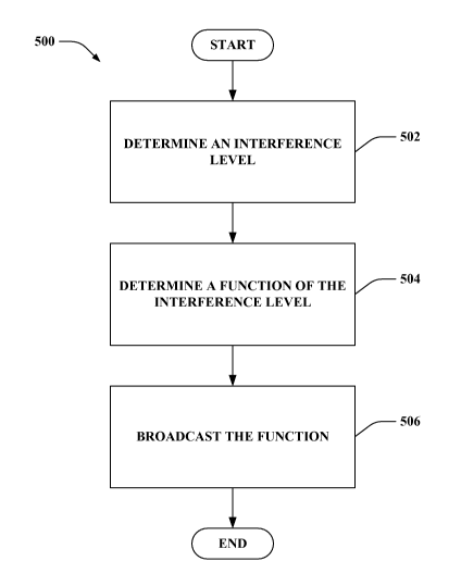
[0066] Turning to Fig. 5, illustrated is a methodology 500 that facilitates
broadcasting interference information in a wireless communication system. At
reference numera1502, an interference level is determined. The interference
level can
be interference received by an access point or base station or the value can
be
transmitted by other access points or base stations over the backhaul. In
accordance
with one aspect, the interference level is represented as an interference over
thermal
(IOT) value. At reference numera1504, a function of the interference level is
determined. Utilizing solely the interference level determined at 502 may
result in
racing conditions among mobile devices. Employing a function of the
interference level
mitigates racing. The function can be an average IOT, a minimum between
received
IOT and a threshold, a minimum between received IOT and an IOT ramp value, a
filtered IOT value or other such function. At reference numera1506, the
function of the
interference level is broadcasted. The function can be broadcasted on a
physical
broadcast channel from a base station to a plurality of mobile devices.
[0067] Turning to Fig. 6, illustrated is a methodology 600 that facilitates
adjusting transmit power level based upon considerations of broadcasted
interference
information. At reference numera1602, interference information is received.
The
interference information can include an interference over thermal value or a
function
thereof. At reference numera1604, a power control offset is determined. The
offset is
determined based upon considerations of the interference information received.
The
received information is employed to map an interference target (e.g., target
C/I, target
SNR, etc.) to a PSD value. The PSD value, for example, can be employed as the
power
control offset utilized to adjust transmit power in accordance with the
received
interference information. At reference numera1606, transmit power is adjusted
based
upon the determined power control offset.
CA 02660715 2009-02-10
WO 2008/031059 PCT/US2007/077921
061671
18
[0068] Now referring to Fig. 7, illustrated is a methodology 700 that
facilitates
setting an initial transmit power level prior to commencing bursty traffic. At
reference
numera1702, an open loop offset is evaluated. The open loop offset value is a
projected
power level adjustment determined during a silence period to prevent a large
sudden
increase in interference. At 704, a transmit power is established in
accordance with the
open loop offset value. At reference numera1706, burst traffic is initiated
utilizing the
adjusted power level to mitigate initial interference increase. After
commencement of
the burst traffic, power control may occur as described supra with reference
to Figs. 5
and 6.
[0069] It will be appreciated that, in accordance with one or more aspects
described herein, inferences can be made regarding determining interference
levels,
determining which functions of interference levels to employ, determining
power level
adjustments based upon considerations of broadcasted interference information,
determining relevant parameters for power level decisions, etc. As used
herein, the term
to "infer" or "inference" refers generally to the process of reasoning about
or inferring
states of the system, environment, and/or user from a set of observations as
captured via
events and/or data. Inference can be employed to identify a specific context
or action,
or can generate a probability distribution over states, for example. The
inference can be
probabilistic-that is, the computation of a probability distribution over
states of interest
based on a consideration of data and events. Inference can also refer to
techniques
employed for composing higher-level events from a set of events and/or data.
Such
inference results in the construction of new events or actions from a set of
observed
events and/or stored event data, whether or not the events are correlated in
close
temporal proximity, and whether the events and data come from one or several
event
and data sources.
[0070] According to an example, one or more methods presented above can
include making inferences pertaining to evaluating an interference level and
choosing a
function of the interference level to mobile devices via a broadcast. By way
of further
illustration, an inference may be made related to determining a power level
adjustment
on a reverse link transmission based upon consideration of broadcasted
interference
information. It will be appreciated that the foregoing examples are
illustrative in nature
and are not intended to limit the number of inferences that can be made or the
manner in
CA 02660715 2009-02-10
WO 2008/031059 PCT/US2007/077921
061671
19
which such inferences are made in conjunction with the various embodiments
and/or
methods described herein.
[0071] Fig. 8 is an illustration of a mobile device 800 that facilitates
adjusting
reverse link power based upon considerations of broadcasted interference
information.
Mobile device 800 comprises a receiver 802 that receives a signal from, for
instance, a
receive antenna (not shown), and performs typical actions thereon (e.g.,
filters,
amplifies, downconverts, etc.) the received signal and digitizes the
conditioned signal to
obtain samples. Receiver 802 can be, for example, an MMSE receiver, and can
comprise a demodulator 804 that can demodulate received symbols and provide
them to
a processor 806 for channel estimation. Processor 806 can be a processor
dedicated to
analyzing information received by receiver 802 and/or generating information
for
transmission by a transmitter 816, a processor that controls one or more
components of
mobile device 800, and/or a processor that both analyzes information received
by
receiver 802, generates information for transmission by transmitter 816, and
controls
one or more components of mobile device 800.
[0072] Mobile device 800 can additionally comprise memory 808 that is
operatively coupled to processor 806 and that may store data to be
transmitted, received
data, information related to available channels, data associated with analyzed
signal
and/or interference strength, information related to an assigned channel,
power, rate, or
the like, and any other suitable information for estimating a channel and
communicating
via the channel. Memory 808 can additionally store protocols and/or algorithms
associated with estimating and/or utilizing a channel (e.g., performance
based, capacity
based, etc.).
[0073] It will be appreciated that the data store (e.g., memory 808) described
herein can be either volatile memory or nonvolatile memory, or can include
both
volatile and nonvolatile memory. By way of illustration, and not limitation,
nonvolatile
memory can include read only memory (ROM), programmable ROM (PROM),
electrically programmable ROM (EPROM), electrically erasable PROM (EEPROM), or
flash memory. Volatile memory can include random access memory (RAM), which
acts as external cache memory. By way of illustration and not limitation, RAM
is
available in many forms such as synchronous RAM (SRAM), dynamic RAM (DRAM),
synchronous DRAM (SDRAM), double data rate SDRAM (DDR SDRAM), enhanced
SDRAM (ESDRAM), Synchlink DRAM (SLDRAM), and direct Rambus RAM
CA 02660715 2009-02-10
WO 2008/031059 PCT/US2007/077921
061671
(DRRAM). The memory 808 of the subject systems and methods is intended to
comprise, without being limited to, these and any other suitable types of
memory.
[0074] Receiver 802 is further operatively coupled to a power level evaluator
810 that determines a power level adjustment for mobile device 800 based upon
broadcasted interference information from a base station. The broadcasted
interference
information may comprise an interference level and/or a function thereof. For
example,
the interference information can be a function comprising a minimum of a
received IOT
value and a IOT threshold for a wireless system. Power level evaluator 810
uses the
interference information to correspond target interference metrics to a delta
power level
value or PSD. Additionally, a power controller 812 may utilize the delta power
level
value or PSD evaluated by power level evaluator 810 to modify the transmit
power level
of mobile device 800. Mobile device 800 still further comprises a modulator
814 and a
transmitter 816 that transmits a signal (e.g., base CQI and differential CQI)
to, for
instance, a base station, another mobile device, etc. Although depicted as
being separate
from the processor 806, it is to be appreciated that power level evaluator
810, power
controller 812 and/or modulator 814 may be part of processor 806 or a number
of
processors (not shown).
[0075] Fig. 9 is an illustration of a system 900 that facilitates reducing the
amount of feedback required to control forward link transmission in a MIMO
system
implementing a PGRC scheme. System 900 comprises a base station 902 (e.g.,
access
point, ...) with a receiver 910 that receives signal(s) from one or more
mobile devices
904 through a plurality of receive antennas 906, and a transmitter 920 that
transmits to
the one or more mobile devices 904 through a transmit antenna 908. Receiver
910 can
receive information from receive antennas 906 and is operatively associated
with a
demodulator 912 that demodulates received information. Demodulated symbols are
analyzed by a processor 914 that can be similar to the processor described
above with
regard to Fig. 8, and which is coupled to a memory 916 that stores information
related
to estimating a signal (e.g., pilot) strength and/or interference strength,
data to be
transmitted to or received from mobile device(s) 904 (or a disparate base
station (not
shown)), and/or any other suitable information related to performing the
various actions
and functions set forth herein. Processor 914 is further coupled to an
interference level
evaluator 918 that determines a level of receive interference and/or a
function thereof.
Interference level evaluator 918 evaluates the interference level or receives
a value over
CA 02660715 2009-02-10
WO 2008/031059 PCT/US2007/077921
061671
21
the backhaul from neighboring sectors. For example, interference level
evaluator 918
may measure the interference received and compare it to thermal to generate an
interference level such as IOT.
[0076] Interference level evaluator 918 is coupled to transmitter 922 through
modulator 920. The interference level determined by interference level
evaluator 918 is
broadcasted by transmitter 922 through transmit antennas 908 to mobile
device(s) 904.
Modulator 920 can multiplex the control information for transmission by a
transmitter
922 through antenna 908 to mobile device(s) 904. Mobile devices 904 can be
similar to
mobile device 800 described with reference to Fig. 8 and employ the
broadcasted
information to adjust power levels on the reverse link. Interference level
evaluator 918
may instruct a function of the interference level to be broadcasted as opposed
to the
instantaneous interference level to mitigate racing conditions. For example,
the
interference information broadcasted can be a minimum of a received IOT or a
IOT
ramp, where the IOT ramp limits the maximum IOT slew. It should be appreciated
that
other functions can be utilized in accordance with the subject disclosure.
Although
depicted as being separate from the processor 914, it is to be appreciated
that
interference level evaluator 918 and/or modulator 920 may be part of processor
914 or a
number of processors (not shown).
[0077] Fig. 10 shows an example wireless communication system 1000. The
wireless communication system 1000 depicts one base station 1010 and one
mobile
device 1050 for sake of brevity. However, it is to be appreciated that system
1000 may
include more than one base station and/or more than one mobile device, wherein
additional base stations and/or mobile devices may be substantially similar or
different
from example base station 1010 and mobile device 1050 described below. In
addition,
it is to be appreciated that base station 1010 and/or mobile device 1050 may
employ the
systems (Figs. 1-4 and 8-9) and/or methods (Figs. 6-7) described herein to
facilitate
wireless communication there between.
[0078] At base station 1010, traffic data for a number of data streams is
provided from a data source 1012 to a transmit (TX) data processor 1014.
According to
an example, each data stream may be transmitted over a respective antenna. TX
data
processor 1014 formats, codes, and interleaves the traffic data stream based
on a
particular coding scheme selected for that data stream to provide coded data.
CA 02660715 2009-02-10
WO 2008/031059 PCT/US2007/077921
061671
22
[0079] The coded data for each data stream may be multiplexed with pilot data
using orthogonal frequency division multiplexing (OFDM) techniques.
Additionally or
alternatively, the pilot symbols can be frequency division multiplexed (FDM),
time
division multiplexed (TDM), or code division multiplexed (CDM). The pilot data
is
typically a known data pattern that is processed in a known manner and may be
used at
mobile device 1050 to estimate channel response. The multiplexed pilot and
coded data
for each data stream may be modulated (e.g., symbol mapped) based on a
particular
modulation scheme (e.g., binary phase-shift keying (BPSK), quadrature phase-
shift
keying (QPSK), M-phase-shift keying (M-PSK), M-quadrature amplitude modulation
(M-QAM), etc.) selected for that data stream to provide modulation symbols.
The data
rate, coding, and modulation for each data stream may be determined by
instructions
performed or provided by processor 1030.
[0080] The modulation symbols for the data streams may be provided to a TX
MIMO processor 1020, which may further process the modulation symbols (e.g.,
for
OFDM). TX MIMO processor 1020 then provides NT modulation symbol streams to NT
transmitters (TMTR) 1022a through 1022t. In various embodiments, TX MIMO
processor 1020 applies beamforming weights to the symbols of the data streams
and to
the antenna from which the symbol is being transmitted.
[0081] Each transmitter 1022 receives and processes a respective symbol stream
to provide one or more analog signals, and further conditions (e.g.,
amplifies, filters,
and upconverts) the analog signals to provide a modulated signal suitable for
transmission over the MIMO channel. Further, NT modulated signals from
transmitters
1022a through 1022t are transmitted from NT antennas 1024a through 1024t,
respectively.
[0082] At mobile device 1050, the transmitted modulated signals are received
by NR antennas 1052a through 1052r and the received signal from each antenna
1052 is
provided to a respective receiver (RCVR) 1054a through 1054r. Each receiver
1054
conditions (e.g., filters, amplifies, and downconverts) a respective signal,
digitizes the
conditioned signal to provide samples, and further processes the samples to
provide a
corresponding "received" symbol stream.
[0083] An RX data processor 1060 may receive and process the NR received
symbol streams from NR receivers 1054 based on a particular receiver
processing
technique to provide NT "detected" symbol streams. RX data processor 1060 may
CA 02660715 2009-02-10
WO 2008/031059 PCT/US2007/077921
061671
23
demodulate, deinterleave, and decode each detected symbol stream to recover
the traffic
data for the data stream. The processing by RX data processor 1060 is
complementary
to that performed by TX MIMO processor 1020 and TX data processor 1014 at base
station 1010.
[0084] A processor 1070 may periodically determine which precoding matrix to
utilize as discussed above. Further, processor 1070 may formulate a reverse
link
message comprising a matrix index portion and a rank value portion.
[0085] The reverse link message may comprise various types of information
regarding the communication link and/or the received data stream. The reverse
link
message may be processed by a TX data processor 1038, which also receives
traffic data
for a number of data streams from a data source 1036, modulated by a modulator
1080,
conditioned by transmitters 1054a through 1054r, and transmitted back to base
station
1010.
[0086] At base station 1010, the modulated signals from mobile device 1050 are
received by antennas 1024, conditioned by receivers 1022, demodulated by a
demodulator 1040, and processed by a RX data processor 1042 to extract the
reverse
link message transmitted by mobile device 1050. Further, processor 1030 may
process
the extracted message to determine which precoding matrix to use for
determining the
beamforming weights.
[0087] Processors 1030 and 1070 may direct (e.g., control, coordinate, manage,
etc.) operation at base station 1010 and mobile device 1050, respectively.
Respective
processors 1030 and 1070 can be associated with memory 1032 and 1072 that
store
program codes and data. Processors 1030 and 1070 can also perform computations
to
derive frequency and impulse response estimates for the uplink and downlink,
respectively.
[0088] It is to be understood that the embodiments described herein may be
implemented in hardware, software, firmware, middleware, microcode, or any
combination thereof. For a hardware implementation, the processing units may
be
implemented within one or more application specific integrated circuits
(ASICs), digital
signal processors (DSPs), digital signal processing devices (DSPDs),
programmable
logic devices (PLDs), field programmable gate arrays (FPGAs), processors,
controllers,
micro-controllers, microprocessors, other electronic units designed to perform
the
functions described herein, or a combination thereof.
CA 02660715 2009-02-10
WO 2008/031059 PCT/US2007/077921
061671
24
[0089] When the embodiments are implemented in software, firmware,
middleware or microcode, program code or code segments, they may be stored in
a
machine-readable medium, such as a storage component. A code segment may
represent a procedure, a function, a subprogram, a program, a routine, a
subroutine, a
module, a software package, a class, or any combination of instructions, data
structures,
or program statements. A code segment may be coupled to another code segment
or a
hardware circuit by passing and/or receiving information, data, arguments,
parameters,
or memory contents. Information, arguments, parameters, data, etc. may be
passed,
forwarded, or transmitted using any suitable means including memory sharing,
message
passing, token passing, network transmission, etc.
[0090] For a software implementation, the techniques described herein may be
implemented with modules (e.g., procedures, functions, and so on) that perform
the
functions described herein. The software codes may be stored in memory units
and
executed by processors. The memory unit may be implemented within the
processor or
external to the processor, in which case it can be communicatively coupled to
the
processor via various means as is known in the art.
[0091] With reference to Fig. 11, illustrated is a system 1100 that
facilitates
generates an interference indication to be broadcasted to a plurality of
mobile devices.
For example, system 1100 may reside at least partially within a base station.
It is to be
appreciated that system 1100 is represented as including functional blocks,
which may
be functional blocks that represent functions implemented by a processor,
software, or
combination thereof (e.g., firmware). System 1100 includes a logical grouping
1102 of
electrical components that can act in conjunction. For instance, logical
grouping 1102
may include an electrical component for identifying an interference level
1104. For
example, mobile devices in non-serving sectors cause interference to a base
station in a
neighboring sector. Further, logical grouping 1102 may comprise an electrical
component for evaluating a function of the interference level 1106. For
example, a
minimum between an interference value received at a base station and an
interference
threshold value can be determined. Employing a function value of the
interference level
mitigates racing conditions that may result when utilizing instantaneous
interference
level values alone. Moreover, logical grouping 1102 may include an electrical
component for transmitting the interference level to a plurality of mobile
devices 1108.
According to an example, a broadcast physical channel can be employed to
convey the
CA 02660715 2009-02-10
WO 2008/031059 PCT/US2007/077921
061671
interference level and/or a function thereof to all mobile devices within a
serving sector.
Additionally, system 1100 may include a memory 1110 that retains instructions
for
executing functions associated with electrical components 1104, 1106, and
1108. While
shown as being external to memory 1110, it is to be understood that one or
more of
electrical components 1104, 1106, and 1108 may exist within memory 1110.
[0092] Turning to Fig. 12, illustrated is a system 1200 that adjusts power on
a
reverse link. System 1200 may reside within a mobile device, for instance. As
depicted, system 1200 includes functional blocks that may represent functions
implemented by a processor, software, or combination thereof (e.g., firmware).
System
1200 includes a logical grouping 1202 of electrical components that facilitate
controlling forward link transmission. Logical grouping 1202 may include an
electrical
component for receiving an interference indication 1204. For example, a
receiver
antenna can be included in a mobile device through which broadcasted signals
from a
serving base station can be captured and processed. The interference
indication includes
information related to interference received at a serving base station caused
by activity
of other mobile devices in non-serving sectors. Moreover, logical grouping
1202 may
include an electrical component for determining a power adjustment value 1206.
For
example, the power adjustment value is evaluated based upon the received
interference
indication. According to one aspect, a power adjustment value that indicates
power
should be increased can be evaluated when the interference indication shows an
increase
in interference. The power increase allows a mobile device to achieve a target
SNR (or
other such target type) despite the increased interference. Further, logical
grouping
1202 may comprise an electrical component for modifying a transmit power level
1208.
After evaluating the power adjustment value, the transmitter on the reverse
link of a
mobile device can be modified by altering the power employed in accordance
with the
adjustment value. Additionally, system 1200 may include a memory 1210 that
retains
instructions for executing functions associated with electrical components
1204, 1206,
and 1208. While shown as being external to memory 1210, it is to be understood
that
electrical components 1204, 1206, and 1208 may exist within memory 1210.
[0093] What has been described above includes examples of one or more
embodiments. It is, of course, not possible to describe every conceivable
combination
of components or methodologies for purposes of describing the aforementioned
embodiments, but one of ordinary skill in the art may recognize that many
further
CA 02660715 2009-02-10
WO 2008/031059 PCT/US2007/077921
061671
26
combinations and permutations of various embodiments are possible.
Accordingly, the
described embodiments are intended to embrace all such alterations,
modifications and
variations that fall within the spirit and scope of the appended claims.
Furthermore, to
the extent that the term "includes" is used in either the detailed description
or the
claims, such term is intended to be inclusive in a manner similar to the term
"comprising" as "comprising" is interpreted when employed as a transitional
word in a
claim.