Language selection

Search

Patent 2660901 Summary

Third-party information liability

Some of the information on this Web page has been provided by external sources. The Government of Canada is not responsible for the accuracy, reliability or currency of the information supplied by external sources. Users wishing to rely upon this information should consult directly with the source of the information. Content provided by external sources is not subject to official languages, privacy and accessibility requirements.

Claims and Abstract availability

Any discrepancies in the text and image of the Claims and Abstract are due to differing posting times. Text of the Claims and Abstract are posted:

  • At the time the application is open to public inspection;
  • At the time of issue of the patent (grant).
(12) Patent Application: (11) CA 2660901
(54) English Title: TKACHYK SAFETY GRATE
(54) French Title: GRILLE DE SECURITE TKACHYK
Status: Dead
Bibliographic Data
Abstracts

English Abstract


The Tkachyk Safety grate is a moveable safety grate designed mainly for use in

grain and material handling bins equipped with safety grates. The design is to
create a
safe and easy way to break up any lumps created in the grain or material
during storage,
which would impede the flow to grain sump,while maintaining adequate safety.
The
width adjustable safety bars are mounted on rails to allow them to move
freely. The
grates are moved via a rod protruding to the exterior of the bin, or by an
optional air
cylinder with air lines running to controls on the exterior of the bin. To aid
in breaking
up of lumps the gate is also equipped with a collapsible metal slat which is
attached to the
sliding grate and can be collapsed when the bin sweep is in use.


Claims

Note: Claims are shown in the official language in which they were submitted.


Claims

1. A safety device mounted above a grain sump consisting of a set of moveable
safety bars mounted on rails for the purpose freeing up frozen, crusted or
lumped
material or grain impeding the flow to the unloading system, while maintaining

protection of moving parts in sump.
- The movement of said safety bars is generated via an external rod or air
powered cylinder.
- A collapsible metal slat is attached to said safety bars for more aggressive

freeing up of material or grain.

2. The safety device of claim 1 wherein said rails provide the mechanism for
movement of safety bars.

3. The safety device of claim 1 wherein said safety bars when set in motion
pros d'
necessary friction for freeing up of material or grain.

4. The safety device of claim 1 wherein said metal slat when set in motion
provides
additional disruption of material and grain.

5. The safety device of claim 1 wherein said safety bars consistently maintain

acceptable openings for protection of moving parts in sump.

6. The safety device of claim 1 wherein said collapsible metal slat referred
to in
claim 4 pivots to lay flat, to allow for minimal interference of other
machinery.

7. The safety device of claim 1 wherein said safety bars vary in length to
accommodate various widths of sump.

8. The safety device of claim 1 wherein said air cylinder is powered via air
lines
running from said cylinder to controls on the exterior of material and grain
hin.

9. The safety device of claim 1 wherein said air cylinder extends and retracts
using
external controls to regulate supply of air lines running to said cylinder.

Description

Note: Descriptions are shown in the official language in which they were submitted.


CA 02660901 2009-04-06

Description
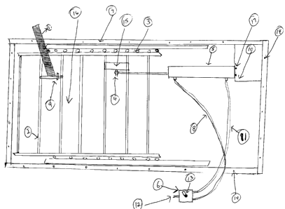
Grain and material bins are equipped with stationary grates covering the sump
vvhich is
where the unloading system allows product or grain to be removed from the bin.
These
bars (2) are there to reduce the chance of an injury or death caused by
contact with the
running unloading system (18). When a lump of grain or product forms in the
bin, the
floes- to the sump (16) and unloading system (18) can be reduced or stopped
completely.
(?ncc this occurs, it is very difficult and dangerous to break up the lumps
and restore full
grain and material flow. The Tkachyk Safety grate allows the movement of the
satety
bars (2) covering the sump (16) in order to loosen up these crusts, and lumps
which are
impeding the flow of material to the unloading system (18). This design is
created to
replace existing stationary safety bars (20), or to be placed in bins which
are not equipped
with safety bars (2) over the sump (16). The safety bars (2) are mounted on a
set of'
railings (3). which allow the unison movement of all bars (2), while still
maintaining an
appropriate opening at maximum to the sump (16). The safety bars (2) can be
slid bacl.
and forth on the rails (3) via a metal rod connected to the bars (2), and
protruding tlrc
exterior of the bin (21). The safety bars(2) mounted to the sliders (3) can
also be moved
by an air powered cylinder (5), which has an extension air line(l 1) and a
retraction air-
line (8) running to an air control valve(6) on the exterior of the bin. The
air cylinder (5) is
mounted below the safety bars, anchored to the mounting frame (7) on
stationary end (Af.
the cylinder, while the moving end of the cylinder is attached to the bars
mounted on rails
(3) using. The extension and retraction of the air cylinder (5) is what
creates the
movement needed to break up lumps reducing grain or material flow. The safety
grate
can he made to fit various widths of sumps by varying the lengths of safety
bars (2).
l here is a metal slat (1) placed perpendicular to the bars (2) to assist in
the breaking up of
lumps and crusts. This slat is held upright with a key, which can be removed
and the slat
lays down by way of the metal slat pivot (9) to allow for a bin sweep (19) to
run overtop
of'it with minimal interference.


CA 02660901 2009-04-06

Summary of Illustration

'I he following are numbered in accordance with the accompanying illustrations
and
photographs

(1) Metal slat
(2) Safety Bar
(3) Sliders/Rails
(4) Cylinder head pin
(5) Cylinder
(6) Air Control Valve
(7) Mounting Frame
(8) Retraction air supply line
(9) Metal slat pivot
(10) Air cylinder mount
(11) Extension air supply line
(12) Main air supply
(13) Air control valve handle
(14) Mounting bolts
(15) Cylinder mounting bracket
(16) Bin sump
(17) Cylinder mounting bolts
(18) Bin unloading system
(19) Bin sweep
(20) Existing stationary safety bars
(21) Loaded Bin

Figure 1 - Labeled drawing
Figure 2 - Cutout Photo of assembled bin
Figure 3 - sketch of bin unloading system
Figure 4 - photo of stationary safety bars
Figure 5 - photo of stationary safety bars and attached bin sweep
Figure 6 - photo of attached bin sweep in working position
Figure 7- Underside Photo of Tkachyk Safety Grate with extended air cylinder
Figure 8 - Topside photo of Tkachyk Safety Grate with retracted air cylinder
Figure 9 - Labeled topside photo of Tkachyk Safety Grate
Figure 10 - Sketch of Loaded bin and unloading system

Representative Drawing
A single figure which represents the drawing illustrating the invention.
Administrative Status

For a clearer understanding of the status of the application/patent presented on this page, the site Disclaimer , as well as the definitions for Patent , Administrative Status , Maintenance Fee  and Payment History  should be consulted.

Administrative Status

Title Date
Forecasted Issue Date Unavailable
(22) Filed 2009-04-06
(41) Open to Public Inspection 2010-10-06
Dead Application 2012-04-10

Abandonment History

Abandonment Date Reason Reinstatement Date
2011-04-06 FAILURE TO PAY APPLICATION MAINTENANCE FEE

Payment History

Fee Type Anniversary Year Due Date Amount Paid Paid Date
Application Fee $200.00 2009-04-06
Owners on Record

Note: Records showing the ownership history in alphabetical order.

Current Owners on Record
TKACHYK, TED F.
Past Owners on Record
None
Past Owners that do not appear in the "Owners on Record" listing will appear in other documentation within the application.
Documents

To view selected files, please enter reCAPTCHA code :


To view images, click a link in the Document Description column. To download the documents, select one or more checkboxes in the first column and then click the "Download Selected in PDF format (Zip Archive)" or the "Download Selected as Single PDF" button.

List of published and non-published patent-specific documents on the CPD .

If you have any difficulty accessing content, you can call the Client Service Centre at 1-866-997-1936 or send them an e-mail at CIPO Client Service Centre.


Document
Description 
Date
(yyyy-mm-dd) 
Number of pages   Size of Image (KB) 
Cover Page 2010-09-21 2 46
Abstract 2009-04-06 1 18
Description 2009-04-06 2 77
Claims 2009-04-06 1 36
Drawings 2009-04-06 4 97
Representative Drawing 2010-09-13 1 14
Correspondence 2009-04-29 1 13
Assignment 2009-04-06 4 241