Note: Descriptions are shown in the official language in which they were submitted.
CA 02660930 2009-03-30
RE-HYDRATION ANTENNA FOR ABLATION
BACKGROUND
Technical Field
[0001] The present disclosure relates generally to devices that may be
used in tissue
ablation procedures. More particularly, the present disclosure relates to
devices and methods for
maintaining ablation temperatures surrounding microwave antennas
radiofrequency probes
during ablation procedures.
Background of Related Art
[0002] In the treatment of diseases such as cancer, certain types of
cancer cells have been
found to denature at elevated temperatures which are slightly lower than
temperatures normally
injurious to healthy cells. These types of treatments, known generally as
hyperthermia therapy,
typically utilize electromagnetic radiation to heat diseased cells to
temperatures above 41
Celsius while maintaining adjacent healthy cells at lower temperatures where
irreversible cell
destruction will not occur. Other procedures utilizing electromagnetic
radiation to heat tissue
also include ablation and coagulation of the tissue. Such ablation procedures,
e.g., such as those
performed for menorrhagia, are typically done to ablate and coagulate the
targeted tissue to
denature or kill the tissue. Many procedures and types of devices utilizing
electromagnetic
radiation therapy are known in the art. Such therapy is typically used in the
treatment of tissue
and organs such as the prostate, heart, kidney, lung, brain, and liver.
1
CA 02660930 2009-03-30
[0003] Presently, there are several types of microwave probes in use,
e.g., monopole,
dipole, and helical, which may be inserted into a patient for the treatment of
tumors by heating
the tissue for a period of time sufficient to cause cell death and necrosis in
the tissue region of
interest. Such microwave probes may be advanced into the patient, e.g.,
laparoscopically or
percutaneously, and into or adjacent to the tumor to be treated. The probe is
sometimes
surrounded by a dielectric sleeve.
[00041 However, in transmitting the microwave energy into the tissue, the
outer surface
of the microwave antenna typically may heat up and unnecessarily desiccate, or
even necrose,
healthy tissue immediately adjacent the antenna outer surface. This creates a
water or tissue
phase transition (steam) that allows the creation of a significant additional
heat transfer
mechanism as the steam escapes from the local/active heating area and re-
condenses further from
the antenna. The condensation back to water deposits significant energy
further from the
antenna/active treatment site. This local tissue desiccation occurs rapidly
resulting in an antenna
impedance mismatch, which both limits power delivery to the antenna and
effectively eliminates
steam production/phase transition as a heat transfer mechanism for tissue
ablation.
[0005] To prevent the charring of adjacent tissue, several different
cooling
methodologies are conventionally employed. For instance, some microwave
antennas utilize
balloons which are inflatable around selective portions of the antenna to cool
the surrounding
tissue. Thus, the complications associated with tissue damaged by the
application of microwave
radiation to the region are minimized. Typically, the cooling system and the
tissue are
maintained in contact to ensure adequate cooling of the tissue.
[0006] Other devices attempt to limit the heating of tissue adjacent the
antenna by
selectively blocking the propagation of the microwave field generated by the
antenna. These
2
CA 02660930 2009-03-30
cooling systems also protect surrounding healthy tissues by selectively
absorbing microwave
radiation and minimizing thermal damage to the tissue by absorbing heat
energy.
SUMMARY
100071 The present disclosure provides a system for use with a microwave
antenna
including a microwave antenna configured to deliver microwave energy from a
power source to
tissue and a sensor module in operative communication with the power source
and configured to
detect a reflectance parameter. The system further includes a jacket adapted
to at least partially
surround the microwave antenna to define a fluid channel between the jacket
and the microwave
antenna. A plurality of fluid distribution ports are defined through the
jacket and are in fluid
communication with the fluid channel to permit the flow of fluid through the
jacket. The system
further includes a fluid pumping system operably coupled to the power source
and configured to
selectively provide cooling fluid to the fluid channel for distribution
through the fluid
distribution ports based on the reflectance parameter.
[0008] In another embodiment, a system for use with a microwave antenna
includes a
microwave antenna configured to deliver microwave energy from a power source
to tissue and a
temperature sensor operably coupled to the microwave antenna and configured to
detect at least
one of a tissue temperature and an antenna temperature. The system further
includes a jacket
adapted to at least partially surround the microwave antenna to define a fluid
channel between
the jacket and the microwave antenna. A plurality of fluid distribution ports
are defined through
the jacket and are in fluid communication with the fluid channel to permit the
flow of fluid
through the jacket. The system further includes a fluid pumping system
operably coupled to the
power source and configured to selectively provide cooling fluid to the fluid
channel for
3
CA 02660930 2009-03-30
distribution through the fluid distribution ports based on a comparison
between the detected
temperature and a predetermined temperature.
100091 The present disclosure also provides for a method for impedance
matching during
an ablation procedure. The method includes the initial steps of applying
microwave energy from
an antenna to tissue and detecting a reflectance parameter. The method also
includes the steps of
analyzing the reflectance parameter to determine an impedance mismatch and
selectively
expelling an amount of fluid from the antenna into the tissue based on the
mismatch. The
method further includes the step of repeating the step of analyzing the
reflectance parameter.
[0010] In another embodiment of the present disclosure, a method for
regulating
temperature of tissue undergoing ablation includes the initial steps of
applying microwave
energy from an antenna to tissue and providing a temperature sensor to detect
at least one of a
tissue temperature and an antenna temperature. The method also includes the
steps of comparing
the detected temperature with a predetermined temperature and selectively
expelling an amount
of fluid from the antenna into the tissue based on the comparison between the
detected
temperature and the predetermined temperature. The method further includes the
step of
repeating the step of comparing the detected temperature with a predetermined
temperature.
[0011] In another embodiment of the present disclosure, a method for
regulating
temperature of tissue undergoing ablation includes the initial steps of
applying microwave
energy from an antenna to tissue and detecting at least one of a tissue
temperature and an antenna
temperature. The method also includes the steps of comparing the detected
temperature with a
predetermined temperature and selectively expelling an amount of fluid from
the antenna into the
tissue based on the comparison between the detected temperature and the
predetermined
4
CA 02660930 2009-03-30
temperature. The method also includes the step of repeating the step of
comparing the detected
temperature with a predetermined temperature.
BRIEF DESCRIPTION OF THE DRAWINGS
10012] The above and other aspects, features, and advantages of the
present disclosure
will become more apparent in light of the following detailed description when
taken in
conjunction with the accompanying drawings in which:
[0013] Fig. 1 is a schematic diagram of a microwave antenna assembly
according to an
embodiment of the present disclosure;
[0014] Fig. 2 is a perspective view of the microwave antenna assembly of
Fig. 1 having
a conduit defined therein;
[0015] Fig. 3 is a cross-sectional view of a microwave antenna according
to one
embodiment of the present disclosure;
[0016] Figs. 4A and 4B are enlarged views of the areas of detail of the
microwave
antenna of Fig. 3;
[0017] Figs. 4C and 4D are alternative embodiments of the area of detail
of the
microwave antenna shown in Fig. 4B;
[0018] Fig. 5 is a schematic block diagram of a generator control system
according to
one embodiment of the present disclosure;
[0019] Fig. 6 is a flowchart diagram showing one method for hydrating
tissue undergoing
treatment according to the present disclosure; and
[0020] Fig. 7 is a flowchart diagram showing another method for hydrating
tissue
undergoing treatment according to the present disclosure.
CA 02660930 2009-03-30
DETAILED DESCRIPTION
[0021] In the drawings and in the description that follows, the term -
proximal", as is
traditional, will refer to the end of the apparatus that is closest to the
clinician, while the term
-distal" will refer to the end that is furthest from the clinician.
[00221 Microwave or radiofrequency ablation is capable of causing
significant
temperature elevations and desiccation of tissue surrounding the applicator.
This elevation of
temperature creates a water or tissue phase transition by which steam escapes
from the active
heating area and recondenses further from the applicator. In this way, the
tissue phase transition
effectively serves as a heat transfer mechanism. As well as adding a new heat
transfer
mechanism, the movement of water, and, specifically, the loss of water in some
volumes of
tissue are expected to affect other tissue properties, such as impedance.
Changes in tissue
thermal properties directly affects the heat conduction within tissue and
changes tissue dielectric
properties that lead to changes in the location of energy deposition within
the targeted, as well as
the surrounding tissues. That is, the condensation back to water deposits
significant energy
further from the active heating area. However, the desiccation of tissue
surrounding the
applicator effectively eliminates steam production as a heat transfer
mechanism and as a result,
the temperature of the active heating area significantly elevates to cause an
impedance mismatch.
[0023] The present disclosure provides for a system and method to re-
hydrate tissue
undergoing treatment through use of various ablation apparatuses (e.g., a
microwave antenna,
radiofrequency probe, pump, etc.), which compensates for the power imbalance
and/or
impedance mismatch that are inherent with dynamic tissue changes. In
particular, hydration of
tissue may be achieved utilizing cooling systems in which cooling fluid is
circulated through and
6
CA 02660930 2009-03-30
expelled from a microwave antenna or radiofrequency probe. The following
disclosure is
directed towards a microwave antenna application; however, teachings of the
present disclosure
may be applied to other types of ablation devices, such as radiofrequency
probes, or even
ultrasonic and laser tissue treatment devices.
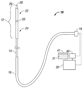
[00241 Fig. 1 shows a diagram of an ablation antenna assembly 10 that may
be any type
of probe suitable for delivering microwave energy and may be used with a
cooling system as
described herein. The antenna assembly 10 generally includes a radiating
portion 12 that may be
coupled by feedline 14 (or shaft) via conduit 16 to connector 18, which may
further connect the
assembly 10 to a power generating source 30 (e.g., a generator) and a supply
pump 40.
[00251 Assembly 10 includes a dipole ablation probe assembly.
Other antenna
assemblies, e.g., monopole or leaky wave antenna assemblies, may also be
utilized. Distal
portion 22 of radiating portion 12 may include a tapered end 26 that
terminates at a tip 28 to
allow for insertion into tissue with minimal resistance. In those cases where
the radiating portion
12 is inserted into a pre-existing opening, tip 28 may be rounded or flat.
[00261 Junction member 20 is located between proximal portion 24 and
distal portion 22
such that a compressive force may be applied by distal and proximal portions
22, 24 upon
junction member 20. Placing distal and proximal portions 22, 24 in a pre-
stressed condition
prior to insertion into tissue enables assembly 10 to maintain a stiffness
that is sufficient to allow
for unaided insertion into the tissue while maintaining a minimal antenna
diameter, as described
in detail below.
[0027] Feedline 14 electrically connects antenna assembly 10 via conduit
16 to generator
30 and typically includes a coaxial cable (not explicitly shown) made of a
conductive metal,
which may be semi-rigid or flexible. Feedline 14 may also have a variable
length from a
CA 02660930 2009-03-30
proximal end of radiating portion 12 to a distal end of conduit 16 ranging
between about 1 to 15
inches. The feedline 14 may be constructed of copper, gold, stainless steel or
other conductive
metals with similar conductivity values. The metals may also be plated with
other materials,
e.g., other conductive materials, to improve conductivity or decrease energy
loss, or for other
purposes known in the art.
[00281 As shown in Fig. 2, conduit 16 includes a flexible coaxial cable
17 and one or
more flexible tubes, namely, inflow tubing 19 and outflow tubing 21 for
supplying and
withdrawing cooling liquid 31 into and out of radiating portion 12,
respectively. Cable 17
includes an inner conductor 23 (e.g., wire) surrounded by an insulating spacer
25, which is
concentrically disposed within an outer conductor 27 (e.g., cylindrical
conducting sheath). Cable
17 may also include an outer insulating sheath 29 surrounding the outer
conductor 27.
Connector 18 couples the inflow tubing 19 and outflow tubing 21 to the supply
pump 40 and the
cable 17 to the generator 30. The supply pump 40 is coupled to a supply tank
41 (Fig. 1) that
stores cooling liquid 31 and maintains the liquid at a predetermined
temperature (e.g., ambient
room temperature). In one embodiment, the supply tank 41 may include a cooling
unit that cools
the returning cooling liquid 31 from the outflow tubing 19.
[0029] The cooling fluid 31 may be pumped using positive pressure through
inflow
tubing 19. Alternatively, negative pressure may also be used to draw the
cooling fluid 31 out of
the region through outflow tubing 21. Negative pressure through outflow tubing
21 may be
utilized either alone or in conjunction with positive pressure through inflow
tubing 19.
Alternatively, positive pressure through inflow tubing 19 may be utilized
either alone or in
conjunction with negative pressure through outflow tubing 21. In pumping the
cooling fluid 31,
the cooling fluid 31 may be passed at a constant flow rate. In another
variation, the flow may be
8
CA 02660930 2009-03-30
intermittent such that a volume of cooling fluid 31 may be pumped into the
radiating portion 12
and allowed to warm up by absorbing heat from the antenna. Once the
temperature of the
cooling fluid 31 reaches a predetermined level below temperatures where
thermal damage to
tissue occurs, the warmed fluid may be removed and displaced by additional
cooling fluids.
[0030] The cooling fluid 31 used may vary depending upon desired cooling
rates and the
desired tissue impedance matching properties. Biocompatible fluids may be
included that have
sufficient specific heat values for absorbing heat generated by radio
frequency ablation probes,
e.g., liquids including, but not limited to, water, saline, liquid
chlorodifluoromethane, etc. In
another variation, gases (such as nitrous oxide, nitrogen, carbon dioxide,
etc.) may also be
utilized as the cooling fluid 31. For example, an aperture defined within the
radiating portion 12
may be configured to take advantage of the cooling effects from the Joule-
Thompson effect, in
which case a gas, e.g., nitrous oxide, may be passed through the aperture to
expand and cool the
radiating portion 12. In yet another variation, a combination of liquids
and/or gases, as
mentioned above, may be utilized as the cooling medium.
[0031] Fig. 3 show a cross-sectional side view and an end view,
respectively, of one
variation of the antenna assembly 10 (e.g., cooling assembly 100) that may be
utilized with any
number of conventional ablation probes (or the ablation probes described
herein), particularly the
straight probe configuration as shown in Fig. 1. Although this variation
illustrates the cooling of
a straight probe antenna, a curved or looped ablation probe may also utilize
much of the same or
similar principles, as further described below.
[0032] Cooling assembly 100 includes a cooling handle assembly 102 and an
elongated
outer jacket 108 extending from handle assembly 102. As will be described in
further detail
below, a plurality of fluid distribution ports 114 (Fig. 4B) are defined
through the thickness of
9
CA 02660930 2009-03-30
outer jacket 108 to facilitate the introduction of cooling fluid 31 from the
cooling assembly 100
into surrounding tissue. Outer jacket 108 extends and terminates at tip 110,
which may be
tapered to a sharpened point to facilitate insertion into and manipulation
within tissue, if
necessary. Antenna 104 is positioned within handle assembly 102 such that the
radiating portion
106 of antenna 104 extends distally into outer jacket 108 towards tip 110.
Inflow tubing 19
extends into a proximal end of handle body 112 and distally into a portion of
outer jacket 108.
Outflow tubing 21 extends from within handle body 112 such that the distal
ends of inflow
tubing 19 and outflow tubing 21 are in fluid communication with one another,
as described in
further detail below.
[00331
Fig. 4A shows handle assembly detail 118 from Fig. 3. As shown, handle body
112 includes proximal handle hub 122, which encloses a proximal end of antenna
104, and distal
handle hub 124, which may extend distally to engage outer jacket 108. Proximal
handle hub 122
and distal handle hub 124 are configured to physically interfit with one
another at hub interface
130 to form a fluid tight seal. Accordingly, proximal handle hub 122 may be
configured to be
received and secured within a correspondingly configured distal handle hub 124
(seen in Fig. 3
as a male-female connection). A slide button 116 is disposed on handle body
112 and operably
coupled to a tube 140 disposed coaxially through at least a portion of outer
jacket 108 (see Figs.
4B and 4C). Movement of the slide button 116 relative to handle body 112, as
depicted in Fig.
4A by bidirectional arrow A, translates corresponding movement of the tube 140
relative to an
inner surface of outer jacket 108, as depicted in Fig. 4B by bidirectional
arrow B, to facilitate the
placement of cooling fluid and/or steam into surrounding tissue, as will be
discussed in further
detail below.
CA 02660930 2009-03-30
[0034] The distal ends of inflow tubing 19 and outflow tubing 21 may be
positioned
within the handle body 112 such that fluid is pumped into handle body 112 via
the supply pump
40 through the inflow tubing 19. Cooling fluid 31 entering the handle body 112
comes into
direct contact with at least a portion of the shaft of the antenna 104 to
allow for convective
cooling of the antenna shaft to occur. The cooling fluid 31 may be allowed to
exit the handle
body 112 via the outflow tubing 21. An additional inlet tube 126 is positioned
within the
antenna cooling assembly 100 to extend between the handle body 112 and the
radiating portion
106 (Fig. 4B) of the antenna 104 and a corresponding outlet tube 128 may also
extend between
the handle body 112 and the radiating portion 106. The proximal end of the
inlet tube 126 is in
fluid communication with the inflow tubing 19 to allow the cooling fluid 31 to
flow distally
within the outer jacket 108 towards antenna radiating portion 106 (Fig. 48).
Alternatively, the
inlet tube 126 and the outlet tube 128 may be omitted from the cooling
assembly 100 and the
outer jacket 108 may remain in direct fluid communication with the inflow
tubing 19 and the
outflow tubing 21 such that cooling fluid 31 contacts the antenna 104 directly
along a portion of
the length, or a majority of the length, or the entire length of the antenna
104. Thus, the cooling
assembly 100 is effective in cooling the antenna 104 directly.
[0035] Fig. 48 shows outer jacket detail embodiment 120, from Fig. 3. The
illustrated
embodiment shows the distal end 132 of inlet tube 126, which extends distally
through outer
jacket 108. The opening at distal end 132 is positioned within outer jacket
108 near or at the
distal end of outer jacket 108 such that distal end 132 opens to fluid channel
134. The cooling
fluid 31 enters fluid channel 134 and fills the volume surrounding the
radiating portion 106 and
surrounding at least a portion of the antenna 104. As cooling fluid 31 enters
fluid channel 134,
the cooling fluid 31 is withdrawn through a distal opening in outlet tube 128,
which is located
11
CA 02660930 2009-03-30
proximally of distal end 132 to allow for increased convective cooling between
the cooling fluid
31 and the antenna 104.
[0036] The cooling fluid 31 is pumped using positive pressure through
inlet tube 126.
Alternatively, negative pressure may also be used to draw the fluid out of the
region through
outlet tube 128. Negative pressure through outlet tube 128 may be utilized
either alone or in
conjunction with positive pressure through inlet tube 126. Alternatively,
positive pressure
through inlet tube 126 may be utilized either alone or in conjunction with
negative pressure
through outlet tube 128.
[0037] The cooling fluid 31 used may vary depending upon desired cooling
rates and the
desired tissue impedance matching properties. Biocompatible fluids having
sufficient specific
heat values for absorbing heat generated by microwave ablation antennas may be
utilized, e.g.,
liquids including, but not limited to, water, saline, Fluorinert , liquid
chlorodifluoromethane,
etc. (As is well-known, the material sold under the trademark Fluorinert is a
perfluorocarbon
fluid distributed commercially by Minnesota Mining and Manufacturing Company
(3M), St.
Paul, Minnesota, USA.)
[0038] The illustrated embodiment in Fig. 4B shows tube 140 and a
plurality of fluid
distribution ports 114 defined through the thickness of the outer jacket 108.
The fluid
distribution ports 114 enable cooling fluid 31 to be expelled from the fluid
channel 134 into
and/or proximate the target tissue. Tube 140 is disposed eoaxially through at
least a portion of
outer jacket 108 such that fluid communication between one or more fluid
distribution ports 114
and fluid channel 134 is selectively interrupted. More specifically, as tube
140 is moved from a
distal most position (see Figs. 4B and 4C) proximally relative to outer jacket
108 by
corresponding proximal movement of slide button 116, an increasing number of
fluid
12
CA 02660930 2009-03-30
distribution ports 114 are exposed to fluid channel 134 from a distal end of
fluid channel 134
toward a proximal end of fluid channel 134, to permit cooling fluid 31 to be
expelled via the
exposed fluid distribution ports 114 into and/or proximate the target tissue.
Similarly, distal
movement of slide button 116 relative to handle body 112 causes distal
movement of tube 140 to
interrupt fluid communication between fluid distribution ports 114 and fluid
channel 134 from a
proximal end thereof toward a distal end thereof In this manner, a user may
manipulate the slide
button 116 relative to the handle body 112 to control the placement of cooling
fluid and/or steam
as desired or depending on the size of the ablation. In some embodiments, the
fluid distribution
ports 114 may be microporous, macroporous, or any combination thereof. The
higher the
porosity, the more freely the cooling fluid 31 will flow through the outer
jacket 108. The fluid
distribution ports 114 may be defined through the outer jacket 108 along the
entire length
thereof Alternatively, the fluid distribution ports 114 may only be defined
through the portion
of the outer jacket 108 that will be adjacent the ablation region (e.g., a
distal end of the radiating
portion 106). The cooling fluid 31 flows outwardly through the fluid
distribution ports 114 as
shown by the arrows extending outwardly therefrom. Alternatively, one or more
of the fluid
distribution ports 114 may be defined at an angle with respect to the surface
of the outer jacket
108 (not explicitly illustrated) such that the cooling fluid 31 may flow
outwardly in various
radial directions (e.g., proximal, distal, etc.).
[0039]
In some embodiments, cooling assembly 100 may include passive-type plugs or
seals (not explicitly shown) to passively seal each fluid distribution port
114. The seals may be
expanded outward by positive fluid pressure communicated through the fluid
distribution ports
114 to allow cooling fluid 31 to be expelled from the cooling assembly 100. In
this way, cooling
fluid 31 may remain circulated within the fluid channel 134 until the supply
pump 40 creates
13
CA 02660930 2009-03-30
additional positive fluid pressure to expand the seals outward, thereby
permitting cooling fluid
31 to exit the fluid channel 134 via the fluid distribution ports 114.
[00401 In some embodiments, the cooling assembly 100 may be configured to
selectively
inject cooling fluid 31 into the surrounding tissue through any one or more
specific fluid
distribution ports 114. That is, cooling fluid 31 may be injected into the
surrounding tissue from
any port or group of ports positioned about the circumference of the outer
jacket 108. In this
configuration, the cooling assembly 100 may include one or more additional
inflow tubes (not
explicitly shown) in direct fluid communication with a specific port or
specific group of ports.
As such, the controller 34 may cause the supply pump 40 to pump cooling fluid
31 through
specific inflow tubes and/or specific groups of inflow tubes into and/or
proximate the
surrounding tissue via specific ports or specific groups of ports. In this
way, cooling fluid 31
may be targeted proximally, distally, or in a specific radial direction.
[00411 Fig. 4C shows an alternative embodiment of inlet tube 126 shown as
a helical
shape extending distally through outer jacket 108. In this configuration,
inlet tube 126 is in
contact with the radiating portion 106 to facilitate faster heating of the
cooling fluid within inlet
tube 126 such that steam may be expelled from a plurality of ports 127
disposed through inlet
tube 126.
[0042J In some embodiments, as shown in Fig. 4D, one or more infusion
inlet tubes 150
may be disposed coaxially through outer jacket 108 to provide infusion fluid
(not shown) directly
from the supply pump 40, as opposed to cooling fluid 31 supplied via inlet
tube 126, such that
infusion fluid and cooling fluid circulate separately within the antenna
assembly 10. In this
scenario, additional inflow tubing (not shown) is disposed in fluid
communication between the
supply pump 40 and infusion inflow tubes 150 and supplies infusion fluid to
the infusion inflow
14
CA 02660930 2009-03-30
tubes 150 using positive pressure from the supply pump 40. Infusion inlet
tubes 150 are in fluid
communication with one or more fluid distribution ports 114 such that positive
pressure from the
supply pump 40 causes the infusion fluid in the infusion inflow tubes 150 to
be expelled from
one or more fluid distribution ports 114 and into and/or proximate the target
tissue. The
embodiment in Fig. 4D may be particularly suitable for radiofrequency
ablation.
[0043]
Fig. 5 shows a schematic block diagram of the generator 30 operably coupled to
the supply pump 40. The supply pump 40 is, in turn, operably coupled to the
supply tank 41.
The generator 30 includes a controller 34, a power supply 37, a microwave
output stage 38, and a
sensor module 32. The power supply 37 provides DC power to the microwave
output stage 38
which then converts the DC power into microwave energy and delivers the
microwave energy to
the radiating portion 106. The controller 34 includes a microprocessor 35
having a memory 36
which may be volatile type memory (e.g., RAM) and/or non-volitile type memory
(e.2., flash
media, disk media, etc.). The microprocessor 35 includes an output port
connected to the supply
pump 40, which allows the microprocessor 35 to control the output of cooling
fluid 31 from the
supply pump 40 to the cooling assembly 100 according to either open and/or
closed control loop
schemes. In the illustrated embodiment, the microprocessor 35 also includes an
output port
connected to the power supply 37 and/or microwave output stage 38 that allows
the
microprocessor 35 to control the output of the generator 30 according to
either open and/or
closed control loop schemes. Further, the cooling assembly 100 may include
suitable input
controls (e.g., buttons, activators, switches, etc.) for manually controlling
the output of the
supply pump 40. Specifically, the input controls may be provided with leads
(or wireless) for
transmitting activation signals to the controller 34. The controller 34 then
signals the supply
pump 40 to control the output of cooling fluid 31 from the supply tank 41 to
the cooling
CA 02660930 2009-03-30
assembly 100. In this way, clinicians may manually control the supply pump 40
to cause cooling
fluid 31 to be expelled from the cooling assembly 100 into and/or proximate
the surrounding
tissue.
[0044] A closed loop control scheme generally includes a feedback control
loop wherein
the sensor module 32 provides feedback to the controller 34 (i.e., information
obtained from one
or more sensing mechanisms for sensing various tissue and/or antenna
parameters, such as tissue
impedance. antenna impedance, tissue temperature. antenna temperature, output
current and/or
voltage, etc.). The controller 34 then signals the supply pump 40 to control
the output thereof
(e.g., the volume of cooling fluid 31 pumped from the supply tank 41 to the
cooling assembly
100). The controller 34 also receives input signals from the input controls of
the generator 30
and/or antenna assembly 10. The controller 34 utilizes the input signals to
adjust the cooling
fluid 31 output of the supply pump 40 and/or the power output of the generator
30.
[0045] The microprocessor 35 is capable of executing software instructions
for
processing data received by the sensor module 32, and for outputting control
signals to the
generator 30 and/or supply pump 40, accordingly. The software instructions,
which are
executable by the controller 34, are stored in the memory 36 of the controller
34.
[0046] The controller 34 may include analog and/or logic circuitry for
processing the
sensed values and determining the control signals that are sent to the
generator 30 and/or supply
pump 40, rather than, or in combination with, the microprocessor 35. The
sensor module 32 may
include a plurality of sensors (not explicitly shown) strategically located
for sensing various
properties or conditions, e.g., tissue impedance, antenna impedance, voltage
at the tissue site,
current at the tissue site, tissue temperature, antenna temperature, etc. The
sensors are provided
with leads (or wireless) for transmitting information to the controller 34.
The sensor module 32
16
CA 02660930 2009-03-30
may include control circuitry that receives information from multiple sensors,
and provides the
information and the source of the information (e.g., the particular sensor
providing the
information) to the controller 34.
[00471 When coupling electromagnetic radiation such as microwaves from a
source to an
applicator, in order to maximize the amount of energy transferred from the
source (microwave
generator) to the load (surgical implement), the line and load impedances
should match. If the
line and load impedances do not match (e.g., an impedance mismatch) a
reflected wave may be
created that can generate a standing wave, which contributes to a power loss
associated with the
impedance mismatch. As used herein, "load impedance" is understood to mean the
impedance
of the radiating portion 12 and -line impedance- is understood to mean the
impedance of the
feedline 14.
[00481 In some embodiments, the controller 34 is configured to control
the cooling fluid
31 output from the supply pump 40 to the antenna assembly 10 based on a
reflectance parameter,
such as a mismatch detected between the load impedance and the line impedance.
Such an
impedance mismatch may cause a portion of the power, so called "reflected
power," from the
generator 30 to not reach the tissue site and cause the power delivered, the
so called -forward
power,- to vary in an irregular or inconsistent manner. It is possible to
determine the impedance
mismatch by measuring and analyzing the reflected and forward power. In
particular, the
generator 30 measures energy delivery properties, namely the forward power,
and dynamically
adjusts the cooling fluid 31 output of the supply pump 40 to compensate for a
detected mismatch
between the line impedance and the load impedance. That is, upon detection of
an impedance
mismatch, additional cooling fluid 31 is pumped through inflow tubing 19 and
into the fluid
channel 134 using positive pressure from the supply pump 40. This positive
pressure causes
17
CA 02660930 2009-03-30
additional fluid pressure in the fluid channel 134, which in turn, causes
cooling fluid 31 to flow
through the fluid distribution ports 114 (e.g., by expanding the seals
outward) into and/or
proximate the surrounding tissue. In this manner, the cooling fluid 31
effectively re-hydrates
surrounding tissue to generate additional steam. This generation of additional
steam allows for
the transfer of heat away from the target tissue site for the duration of the
procedure. The
resulting drop in tissue temperature (or more specifically, a change in a
dielectric constant el of
the tissue surrounding the antenna) effectively lowers the load impedance to
match the line
impedance, thereby optimizing energy delivery to the target tissue site. Other
reflectance
parameters include reflectance coefficient, standing wave ratio (SWR), and
reflectance loss.
[0049] In operation, the sensor module 32 is coupled to the microwave output
stage 37 and is
configured to measure a reflectance parameter. The sensor module 32 may
include one or more
directional couplers or other voltage and current sensors that may be used to
determine voltage
and current measurements as well as the phase of the voltage and current
waveforms. The
voltage and current measurements are then used by the sensor module 32 to
determine the
reflectance parameter.
The sensor module 32 converts the measured parameter into
corresponding low level measurement signals (e.g., less than 5 V) which are
transmitted to the
controller 34.
[0050]
The controller 34 accepts one or more measurements signals indicative of power
delivery, namely, the signals indicative of the reflectance parameter. The
controller 34 analyzes
the measurement signals and determines an impedance mismatch based on the
reflectance
parameter. The controller 34 thereafter determines whether any adjustments to
the output of the
supply pump 40 have to be made to adjust (e.g., re-hydrate) the surrounding
tissue to compensate
for the mismatch in impedance based on the reflectance parameter.
Additionally, the controller
18
CA 02660930 2009-03-30
34 may also signal the microwave output stage 38 and/or the power supply 37 to
adjust output
power based on the reflectance parameter.
[0051] Fig. 6, in conjunction with Figs. 3, 4A, 4B, and 5, illustrates a
method 200 for
selectively re-hydrating tissue undergoing treatment according to one
embodiment. In step 210,
energy from the generator 30 is applied to tissue via the antenna 104 to heat
a target treatment
area. In step 235, one or more reflectance parameters are detected by the
sensor module 32 (e.g.,
using sensors) and communicated to the controller 34 for storage in the memory
36. In the
illustrated embodiment, the reflectance parameters detected in step 235
include a load impedance
(detected in step 220) and a line impedance (detected in step 230). In step
240, the
microprocessor 35 compares the load impedance to the line impedance. If the
load impedance
and the line impedance are not at least substantially equivalent in step 250,
the microprocessor
35 outputs a control signal to the supply pump 40 in step 260 to cause cooling
fluid 31 to be
expelled from the cooling assembly 100 into and/or proximate the surrounding
tissue. If the load
impedance and line impedance are substantially equivalent in step 250, step
240 is repeated. The
method 200 may loop continuously throughout the duration of the procedure to
re-hydrate the
target tissue and generate additional steam as a heat transfer mechanism. The
resulting drop in
tissue temperature (or change in dielectric constant el of the tissue
surrounding the antenna) acts
to improve energy delivery to the target tissue by facilitating an impedance
match between the
line and the load.
[00521 Fig. 7, in conjunction with Figs. 3, 4A, 4B, and 5, illustrates a
method 300 for
selectively re-hydrating tissue undergoing treatment according to another
embodiment. In step
310, energy from the generator 30 is applied to tissue via the antenna 104 to
heat a target
treatment area. In step 320, a tissue temperature and/or an antenna
temperature is detected by the
19
CA 02660930 2009-03-30
sensor module 32 (e.g., using an optical temperature sensor) and communicated
to the controller
34 for storage in the memory 36. In step 330, the microprocessor 35 compares
the detected
temperature to a predetermined temperature (e.g., about 104 C). If the
detected temperature is
greater than or equal to the predetermined temperature in step 340, the
microprocessor 35
outputs a control signal to the supply pump 40 in step 350 to cause cooling
fluid to be expelled
from the cooling assembly 100 into and/or proximate the surrounding tissue. If
the detected
temperature is less than the predetermined temperature in step 340, step 330
is repeated The
method 300 may loop continuously throughout the duration of the procedure to
re-hydrate the
target tissue and generate additional steam as a heat transfer mechanism. The
resulting drop in
tissue temperature acts to improve energy delivery by maintaining the target
tissue site at a
temperature below a temperature at which significant tissue dehydration may
occur.
100531 In some embodiments, the disclosed methods may be extended to other
tissue
effects and energy-based modalities including, but not limited to, ultrasonic
and laser tissue
treatments. The methods 200 and 300 are based on impedance measurement and
monitoring and
temperature measurement and monitoring, respectively, but other tissue and
energy properties
may be used to determine state of the tissue, such as current, voltage, power,
energy, phase of
voltage and current. In some embodiments, the method may be carried out using
a feedback
system incorporated into an electrosurgical system or may be a stand-alone
modular embodiment
(e.g., removable modular circuit configured to be electrically coupled to
various components,
such as a generator, of the electrosurgical system).
[00541 While several embodiments of the disclosure have been shown in the
drawings
and/or discussed herein, it is not intended that the disclosure be limited
thereto, as it is intended
that the disclosure be as broad in scope as the art will allow and that the
specification be read
CA 02660930 2016-03-10
likewise. Therefore, the above description should not be construed as
limiting, but merely as
exemplifications of particular embodiments. The scope of the claims should not
be limited by the
preferred embodiments set forth herein, but should be given the broadest
interpretation consistent
with the description as a whole.
=
21