Note: Descriptions are shown in the official language in which they were submitted.
CA 02661077 2009-02-16
WO 2008/020053 PCT/EP2007/058509
PROCESS FOR FRACTIONATING A HYDROCARBONACEOUS
CATALYTICALLY CRACKED PRODUCT STREAM AND A FRACTIONATION
COLUMN THEREFORE
The present invention relates to a process for
fractionating a hydrocarbonaceous catalytically cracked
product stream. It also relates to a fractionation column
therefore. In a further aspect the invention relates to a
process for catalytic cracking in which such a
fractionation process is being used.
Catalytic cracking is a well-known process that is
being widely used in many refineries. In catalytic
cracking a hydrocarbon feedstock is fed to a riser
reactor into which also a cracking catalyst is fed.
During the residence time in the riser reactor the
hydrocarbon feedstock is being cracked into lighter
products. At cracking also some coke is being formed that
deposits onto the cracking catalyst to yield spent
catalyst. At the top of the riser reactor the product
stream is separated from the spent catalyst, and the
spent catalyst is then regenerated by burning off the
coke using a regenerating gas. The regenerated catalyst
is subsequently recycled to the riser reactor. The heat
for the catalytic cracking reaction is supplied by the
regenerated catalyst. The vaporous product stream of the
catalytic cracking process is separated into various
fractions, such as C4--alkanes and olefins, naphtha,
distillate oils and cycle oils in a fractionation column.
In the fractionation of the hot vaporous product
stream it is desirable to recycle or reflux at least a
portion of the oil that collects in the bottom of the
fractionator via a suitable heat exchanger to cool the
CA 02661077 2009-02-16
WO 2008/020053 PCT/EP2007/058509
- 2 -
oil prior to its reintroduction into the
fractionator. This technique is commonly referred to as
slurry oil pumparound. The oil moving downwardly through
the upper portion of the fractionator is highly heated
due to contact with the hot vaporous product stream from
the FCC riser reactor, which effluent is typically at a
temperature in the range from about 450 to about 550 C.
In US-A-4776948 it was recognised that the heat
exchanger used to cool the slurry oil is subject to
intermittent fouling when in service, which fouling
causes undesirable reductions in the FCC unit operating
capacity. It was proposed to quench the product stream
with a cold slurry oil to a temperature below that at
which slurry oil will polymerize and/or form coke or coke
precursors by allowing a liquid to flow over an inclined
baffle plate downward in the column. This specification
is silent about the specific problems concerning the
inlet of the fractionation column.
The phenomenon of coke-forming material in the
transfer line to the main fractionator was recognised in
US-A-5258113. As is described in US-A-5258113 refineries
tend to maximise the yield on olefins and gasoline and at
the same time to use increasingly heavier feeds. However,
by striving to these objectives the effluents tend to
contain more coke and more reactive materials that tend
to form coke. In US-A-5258113 it was found that the coke
deposition in the transfer line to the fractionation
column was caused by thermal formation of free radicals,
which polymerized and laid down coke in the transfer
line. As solution it was proposed to add coke-suppressing
additives. This has the disadvantage that alien molecules
are added to the hydrocarbonaceous feedstock or products.
CA 02661077 2009-02-16
WO 2008/020053 PCT/EP2007/058509
- 3 -
We now found that coke deposits that close off the
inlet to the fractionation column are found to be formed
by down-flowing streams in the fractionation column. This
is specially the case when a recycle of at least a
portion of the oil that collects in the bottom of the
fractionation column is used to cool the hot vaporous
product stream that enters the column. It has now been
found that the building up or clogging of the inlet by
coke deposits can be prevented by passing at least a
portion of the product stream upward into the
fractionation column.
Accordingly, the present invention provides a process
for fractionating a hydrocarbonaceous catalytically
cracked product stream comprising: a) passing said
product stream to a vertical fractionation column through
an inlet; b) redirecting a part of the product stream
upon entering the fractionation column upwards into the
fractionation column by using a baffle; c) separating the
product stream into one or more hydrocarbonaceous
fractions; and d) discharging the fractions from the
fractionation column.
The invention provides that a vapour of product
stream is actively passed upwards into the fractionation
column. By actively is meant that the amount of product
stream and the velocity of that product stream is higher
than normally would be when no action is being taken. By
this action it is believed that liquid material that
drops down from any internals in the fractionation column
or the liquid material of the recycle used for cooling
and that may comprise coke-forming components is swept
from the area around the inlet so that no coke is
deposited in this inlet area.
CA 02661077 2009-02-16
PCT/EP 2007/058 50''.
Printed.21/08/2008 !DESCPAMD =EP2007058509` WO 2008/020053 PCTIEP2007/058509
- 4 -
Part of the product stream is redirected upwards
into the fractionation column upon entering the EPO DG 7;
fractionation column by using a baffle. The baffle T1 07. 2008
deflects a part of the product.stream upwards into the
fractionation column such that any liqiuid material that
drips down is removed from the inlet area, whereas the
other part of the product stream is passed straight to
the middle of the fractionation column so that a good
distribution of.the vaporous product stream over the
cross-section=of the fractionation column is obtained.
Accordingly, in a second aspect of this invention, there
is provided_a.fractionation column comprising an inlet
for a product stream and one or more outlets for one or
more hydrocarbonaceous fractions, wherein the column is
further provided with a baffle in front of the location
of the inlet for the product stream, the baffle covering
ar of1~ the ross sectio of the inlet L1Vlt~ &n A. F~
p of ~ 0 ~
~t7[0 ~ " vL
~~T~ie parross section of the inlet that is
"6A
covered by the baffle preferably ranges from 20 to 80%,
more preferably from 40 to 60%. Even more preferably,
about 50% of. the cross section of the inlet is covered by
the baffle. =
Preferably, the part of the product stream is
redirected upwards along the inner wall of the
fractionation column. However, there.are situations where
the inner wall cannot be used sufficiently. This is for
example the case when the conduit is extended into the
fractionation column. This might be the case when~the
inner wall is not straight or whenthe conduit is
narrowed to reach a preferred velocity at the inlet. In
these cases a so-called dummy wall may be added at the
end of the pipe.-This dummy wall may.be"a ring added at
the end of the pipe and in this way serves as a wall.
~:: AMENDED SHEET 11/07
"
CA 02661077 2009-02-16
WO 2008/020053 PCT/EP2007/058509
- 5 -
This ring has a diameter preferably at least 2 times,
more preferably at least 2.5 times the diameter of the
conduit.
It is clear that the baffle must be positioned such
that there is significant impact of the product stream
onto the baffle. Therefore the baffle is suitably at an
angle with the direction of the product stream. More
preferably, the baffle is substantially perpendicularly
positioned vis-a-vis the flow direction of the product
stream. By substantially in this context is understood
that deviations up to 15 are possible.
It is desirable to reintroduce at least part of the
hydrocarbonaceous fraction that collects in the bottom of
the fractionation column into the fractionation column.
Generally, this hydrocarbonaceous fraction is an oily
fraction, furthermore comprising catalyst fines.
Preferably, the fraction is cooled before it is
reintroduced. More preferably, the fraction is cooled by
passing it through a heat exchanger. To reintroduce the
fraction, preferably the column comprises an inlet for
reintroducing at least part of the hydrocarbonaceous
fraction that collects in the bottom of the fractionation
column. More preferably, the inlet for reintroducing the
hydrocarbonaceous fraction is located higher than the
inlet for the product stream.
It will be evident to the skilled person that the
fractionation column may be provided with the usual
plurality of fractionation internals, in particular
trays. Such trays may be of the bubble-cap, sieve, plate,
grid tray, packing or other types. The trays provide
contact between liquid and vapour such that separation of
hydrocarbons into different fractions occurs as the
hydrocarbons condense and evaporate on the trays.
CA 02661077 2009-02-16
WO 2008/020053 PCT/EP2007/058509
- 6 -
The baffle may have several shapes. It is most
convenient that the shape of the baffle corresponds with
the shape of the inlet. Since it is almost universal that
the inlets to fractionation columns are circular it is
preferred that the baffle also relates its shape to a
circle. Since only part of the product stream needs to be
deflected, the baffle preferably has the shape of a
circular segment. Even more preferred, the baffle has the
shape of a semi-circle. By this shape it is possible to
adjust the portion of the product stream that is passed
unhindered into the fractionation column as required. For
an optimal deflection, the radius of the baffle, having
the shape of a semi-circle, is at least as large as the
radius of the inlet. Suitably, the radius of the baffle
is from 1 to 2 times the radius of the inlet.
The thickness of the baffle depends on the size, on
the material the baffle is made from and on the
construction details of the fractionation column and the
inlet. Preferably, the thickness of the baffle is between
8 and 50 mm, more preferably between 10 and 35 mm, most
preferably between 12 and 25 mm. The skilled person will
know what material to use to construct the baffle.
Preferably, the material of the baffle is the same as the
material of the fractionation column. Suitably, a type of
stainless steel or carbon steel may be used.
The skilled person may determine what part of the
product flow is passed directly into the fractionation
column and what part is passed along the inner wall of
the fractionation column, suitably by passing this part
onto the baffle described. Suitably the part that is fed
directly into the centre of the fractionation column
ranges from 20 to 80%, preferably from 40 to 60%. More
preferably, about 50% of the product stream is passed
CA 02661077 2009-02-16
WO 2008/020053 PCT/EP2007/058509
- 7 -
directly into the centre of the fractionation column and
another 50% against a baffle with subsequent flow along
the inner wall of the column.
The velocity with which the product stream impinges
upon the baffle at the inlet side may prevent that coke
is being formed on the baffle, even when a very heavy
feedstock is being used. However, since it is believed
that liquid material that drops down from any internals
in the fractionation column and that may comprise coke-
forming components is swept from the area around the
inlet, this liquid material may drip down via the other
side of the baffle so that coke may be deposited on that
side of the baffle. To prevent this from happening, the
baffle is suitably provided with a hole. Through this
hole a small portion of the product stream passes through
the baffle. In addition to the product stream that
already is deflected by the baffle, this gas stream will
blow away any coke that may deposit on the baffle. It is
even more effective when preferably a second baffle has
been provided downstream the hole that also redirects the
small portion product stream that comes through that hole
along the surface of the baffle. The dimensions and the
shape of the hole can be selected by the skilled person,
dependent on the heaviness of the feed, on the
composition and amount of the product stream and on the
conditions in the fractionation column. The hole is
suitably circular and has a radius ranging from 0.1 to
0.3 times the radius of the inlet. The dimensions and
shape of the second baffle can also be selected by the
skilled person, depending on the circumstances. The
second baffle suitably has a shape corresponding to the
shape of the hole. When circular, the radius of the
second baffle is from 1 to 2 times the radius of the
CA 02661077 2009-02-16
WO 2008/020053 PCT/EP2007/058509
- 8 -
hole. The second baffle is located downstream the hole,
at a distance preferably ranging from 0.1 to 10 times the
radius of the hole, more preferably at a distance 0.1 to
2 times the radius of the hole.
The baffle is arranged in front of the inlet. The
distance from the wall of the fractionation column, at
which the baffle has been positioned, suitably ranges
from 0.1 to 1.0 times the radius of the inlet. Within
this range the skilled person is able to adjust the
velocity such that an optimal sweeping away of liquid
material is ascertained. The baffle extends preferably
parallel to the inner wall of the fractionation column.
That could mean that the baffle has the same curvature as
the fractionation column.
It has been found that the velocity of the product
stream plays a role in the process of the invention.
Evidently, the most preferred velocity is dependent on
other conditions in the fractionation column. In a fluid
catalytic cracking process the conditions in a main
fractionation column include a temperature ranging from
400 to 600 C at the inlet of the column and a pressure of
1 to 5 bara. In such conditions the superficial velocity
of the product stream at the inlet of the fractionation
column is suitably at least 25 m/s, more preferably at
least 30 m/s, even more preferably at least 35 m/s.
Superficial velocity is defined as [volume flow of the
gas] / [cross sectional area of the pipe]. The lower
limits in velocity are to a large extent determined by
the economics (lower velocity needs a too large size of
the plant), fouling of the inlet pipe and a too long
residence time in the inlet pipe. Evidently there are
also optimal upper limits to the velocity. These are to a
large extent determined by the disturbance of the
CA 02661077 2009-02-16
WO 2008/020053 PCT/EP2007/058509
- 9 -
fractionation process in the vessel. Suitably, the
superficial velocity of the product stream at the inlet
of the fractionation column is not more than 80 m/s,
preferably not more than 60 m/s. If the product stream
velocity at the inlet is not optimal the skilled person
may make the inlet either more narrow to increase the
velocity, or broaden the inlet to lower the velocity. The
narrowing down of the inlet may be achieved by applying a
conical device into the conduit that ends at the inlet of
the fractionation column.
The velocity of the part of the product stream that
is passed along the wall of the fractionation column is
preferably at least half the velocity of the product
stream at the inlet. More preferably, the velocity is at
least the same velocity of the product stream at the
inlet. It is evident that the velocity of the product
stream has an influence on the velocity and effectiveness
of the sweeping effect of the part that is passed along
the wall of the column. Another feature that the skilled
person has, to influence the velocity of this part of the
product stream, is the positioning of the baffle that
suitably may be at a distance from the inlet, ranging
from 0.1 to 1.0 times the radius of the inlet.
The fractionation process of the present invention
can excellently be used in the catalytic cracking of
hydrocarbons. Accordingly, in a further aspect, the
present invention provides a process for catalytic
cracking of a hydrocarbon feedstock comprising feeding
the feedstock to a riser reactor into which also cracking
catalyst is fed, followed by removing from the top of the
riser reactor a hydrocarbonaceous catalytically cracked
product stream and spent catalyst; separating the spent
catalyst from the catalytically cracked product stream;
CA 02661077 2009-02-16
WO 2008/020053 PCT/EP2007/058509
- 10 -
regenerating the spent catalyst with a regeneration gas
to produce regenerated catalyst; and feeding regenerated
catalyst as cracking catalyst to the riser reactor;
wherein the catalytically cracked product stream is
fractionated in a process comprising: a) passing said
product stream to a vertical fractionation column through
an inlet; b) redirecting a part of the product stream
upon entering the fractionation column upwards into the
fractionation column; c) separating the product stream
into one or more hydrocarbonaceous fractions; and d)
discharging the fractions from the fractionation column.
The invention will be further explained by reference
to the following figures.
Figure 1 shows a preferred embodiment of a catalytic
cracking process.
Figure 2 shows a preferred embodiment of the inlet of
a fractionation column comprising a baffle.
Figure 3 shows a preferred embodiment of the top view
of a cross-section of the inlet of the fractionation
column.
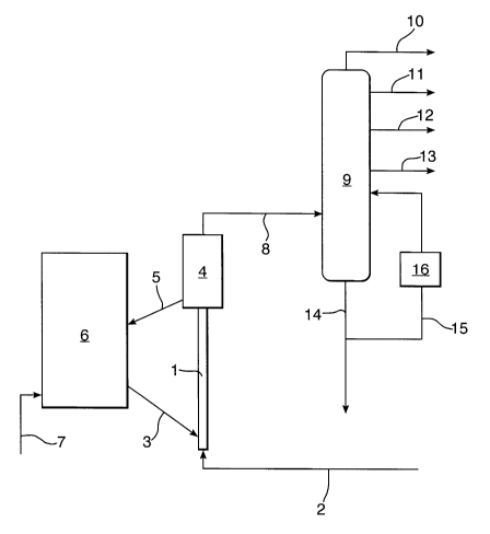
Figure 1 shows a riser reactor (1) into which a
hydrocarbon feedstock is fed via conduit (2) into the
riser reactor (1). Via a conduit (3) hot regenerated
catalyst is also fed into the reactor (1). The mixture of
catalyst and hydrocarbon feedstock is passed upwards,
while the feedstock is being cracked resulting in spent
catalyst and cracked products. The riser reactor (1)
debouches into a stripper zone (4) where the cracked
products are stripped from the spent catalyst. Usually in
the top of the stripper also cyclones are present,
wherein the stripped catalyst is separated from the
product stream. The stripped catalyst is passed to a
regenerator (6) via a conduit (5). Into the
CA 02661077 2009-02-16
WO 2008/020053 PCT/EP2007/058509
- 11 -
regenerator (6) a regenerator gas, usually an oxygen-
containing gas, e.g., air, is fed into the
regenerator (6) to burn off any coke present on the spent
catalyst. The regenerated catalyst is discharged via the
conduit (3) and fed into the riser reactor (1).
The cracked products are withdrawn from the stripping
zone (4) via line (8) and fed into a fractionation
column (9). In the fractionation column the product
stream is separated into a number of fractions that are
discharged via lines (10), (11), (12) and (13). It will
be evident to the skilled person that the number of
fractions can be varied. A heavy liquid fraction may be
discharged from the fractionation column via line (14).
This heavy fraction may contain all the catalyst fines
that have been carried over from the reactor and/or the
stripper. This stream may be (partly) fed back to the
column via line (15). Before entering the fractionation
column above the inlet of line (8) the stream is cooled
in heat exchanger (16).
Figure 2 shows a more detailed view of the inlet of
the fractionation column. It shows a wall (20) of a
fractionation column into which a conduit (21) for the
supply of hydrocarbonaceous product stream debouches at
an inlet (22). Via one or more supports (23) a semi-
circular baffle (24) is provided at a short distance from
the inlet (22). The radius of the baffle is larger than
the radius of the conduit (21). Good results have been
obtained when the baffle radius is about 1.5 times
bigger. The baffle has been provided with a hole (25)
having a radius that may be from one fifth to one
twentieth, in particular about one eighth, of the radius
of the inlet (22). Downstream of the hole there is
CA 02661077 2009-02-16
WO 2008/020053 PCT/EP2007/058509
- 12 -
provided a second smaller baffle (26) to deflect any
product stream that passes through the hole (25).
Figure 3 shows a top view of the baffle of Figure 2.
The figure shows that the baffle (24) is connected to the
wall (20) of the fractionation column via supports (23).
It also shows that the baffle (24) extends parallel to
the wall (20) following the same curvature.