Note: Descriptions are shown in the official language in which they were submitted.
CA 02661313 2010-12-31
1
FOUR WHEEL DRIVE SYSTEM
FIELD OF THE INVENTION
[0001] The present invention relates to the field of zero turning radius
vehicles and, more particularly, to four wheel drive systems.
BACKGROUND OF THE INVENTION
100021 There has always been a trade off between traction and
maneuverability in vehicles, particularly heavy equipment vehicles, tractors,
and the
like.. Tractors were generally not considered for four wheel drive systems
because it
was believed that deliberate weight distribution and bilaterally independent
brakes
on the drive wheels would be sufficient for maximum tractive force. Moreover,
there are difficulties in providing a driving force to the front steering
wheels of such
vehicles. If the steering wheels were given drive capability, it would be
advantageous to make the steering wheels larger for greater traction. However,
larger front steering wheels would interfere with the framework of the
vehicle,
thereby limiting their usefulness. In addition, conventional differentials
required to
drive the steering wheels are complex and expensive. With the advent of zero
turning radius vehicles capable of turning in a reverse direction within the
length of
the vehicle, there is a greater need for improved traction. Some such vehicles
have
steering wheels which pivot about vertical axes in place of less directionally
stable
caster wheels. The present invention relates to zero turning radius vehicles
in which
the steering wheels are both driven and rotated about their vertical axes to
control
the steering and propulsion forces thereto.
BRIEF DESCRIPTION OF THE PRIOR ART
100031 Various devices have been used to decrease the turning radius of
four
wheel drive tractors. Kubota uses a Bi-Speed turning mechanism wherein
variable
speeds are used for the front axle relative to the back. Kubota also
manufactures a
system where clutches are used in place of a differential between the rear
wheels so
that in tight turns, the system is practically a four wheel vehicle with the
three
outside wheels being driven. Others have used steerable axles where the entire
axle
pivots about its vertical axis. Other methods of decreasing turning radii
while
CA 02661313 2010-12-31
2
maintaining four wheel drive include four wheel steering, skid steering such
as
provided by Ingersoll Rand, and articulated steering. However, other than skid
steering, none of these devices allow a zero turn radius. Moreover, the zero
turning
radius vehicles known in the art are not provided with four wheel drive
because of
the complexities of driving the steering wheels as set forth above. The
present
invention was developed in order to overcome these and other drawbacks of the
prior devices by providing a four wheel drive vehicle which also has zero
turning
radius capabilities.
SUMMARY OF THE INVENTION
[00041 The four wheel drive system of the invention is suitable for use
with
bilaterally symmetrical vehicles having a pair of front wheels and a pair of
rear
wheels. Each of the rear wheels is connected with the vehicle for rotation
about a
vertical axis to provide steering for the vehicle. A first drive system
independently
rotates the front wheels about horizontal axes and a second drive system
independently rotates the rear wheels about horizontal axes to propel the
vehicle in
forward and reverse directions. The second drive system further independently
rotates the rear wheels about their vertical axes to steer the vehicle. The
rear wheels
can be turned through 360 degrees to provide the vehicle with a zero turning
radius.
A controller is connected with the first and second drive systems to control
the
operation thereof to propel and steer the vehicle in a desired direction. The
controller is also preferably connected with each wheel to receive signals
from the
wheels corresponding to the horizontal rotation thereof and to the turning
position of
the rear wheels.
[0005] The drive systems comprise hydraulic pumps or motors. The second
drive system includes two pumps, one for delivering a propulsion force to the
rear
wheels and another for delivering a steering force to the rear wheels.
[0006] In an alternate configuration, the first drive system for the front
wheels includes a power source, a power splitter connected with the power
source,
and a pair of opposed drive mechanisms connected with the power splitter and
the
front wheels. Each drive mechanism includes a first differential clutch
connected
CA 02661313 2010-12-31
3
with the power splitter and a second differential clutch connected with the
first
differential clutch. First and second braking devices are connected between
the
first and second differential clutches to control the delivery of power from
the
power splitter to each wheel. Operation of the first and second braking
devices
controls the degree and direction of driving power being delivered from the
power
source to the wheels. In a preferred embodiment, hydraulic pumps act as the
braking devices and appropriate valves and controls avoid the need for
separate
pumps.
According to an aspect of the present invention, there is provided a
four wheel drive system for a bilaterally symmetrical vehicle having pairs of
front
and rear wheels, respectively, comprising:
(a) a first drive system for independently rotating each of the front wheels
in forward and reverse directions about a first horizontal axis to propel the
vehicle;
(b) a second drive system for independently rotating each of the rear
wheels about a second horizontal axis at similar speeds in the same direction
to
propel the vehicle;
(c) said rear wheels further being connected with said vehicle for rotation
about vertical axes, respectively, beyond 180 degrees;
(d) a third drive system independently rotating the rear wheels about
vertical axes to steer the vehicle; and
(e) a controller connected with said first, second and third drive systems
for controlling the operation thereof to steer and propel the vehicle, said
controller
operating said first drive system to simultaneously rotate said front wheels
in
opposite directions when executing a sharp turn approaching a turning radius
of
zero.
According to another aspect of the present invention, there is provided a
steering mechanism for a vehicle, comprising:
(a) a pair of axles;
(b) a pair of wheels connected with said axles for driven rotation about
horizontal axes, respectively, said wheels further being actively rotatable
through
greater than 180 degrees about vertical axes with respect to said axles;
CA 02661313 2010-12-31
4
(c) a first drive system connected with front wheels to drive said front
wheels in forward and reverse directions about said horizontal axes and a
second
drive system connected with said pair of wheels to independently rotate said
pair
of wheels about said vertical axes; and
(d) a controller connected with said first and second drive systems for
controlling the operation thereof to steer and propel the vehicle in
accordance with
operator input to said controller, said controller operating said first drive
system to
simultaneously rotate said front wheels in opposite directions when executing
a
sharp turn approaching a turning radius of zero.
According to a further aspect of the present invention, there is
provided a four wheel drive system for a bilaterally symmetrical vehicle
having a
longitudinal axis and pairs of front and rear wheels, respectively,
comprising:
(a) a propelling drive system for rotating each of the front wheels in
forward and reverse directions about a horizontal axis to propel the vehicle,
said
propelling drive system further rotating each of rear wheels about a
horizontal axis
at similar speeds in the same direction to propel the vehicle;
(b) the rear wheels further being connected with said vehicle for rotation
about vertical axes, respectively;
(c) a steering drive system for rotating the rear wheels about vertical axes
up to 90 relative to said vehicle longitudinal axis to steer the vehicle; and
(e) a controller connected with said propelling and steering drive systems
for controlling the operation thereof to propel and steer the vehicle, said
controller
operating said propelling drive system to simultaneously rotate said front
wheels
in opposite directions when executing a sharp turn approaching a turning
radius of
zero.
BRIEF DESCRIPTION OF THE FIGURES
[00071 Other objects and advantages of the invention will become
apparent from a study of the following specification when viewed in the light
of
the accompanying drawing, in which:
[0008] Fig. 1 is a schematic view of the four wheel drive system according
to an embodiment of the invention;
CA 02661313 2010-12-31
[0009] Figs. 2 and 3 are front and perspective views, respectively, of one
of
the rear steering wheels of the vehicle;
[0010] Fig. 4 is a schematic view of a preferred drive system for the front
wheels of the vehicle; and
[0011] Fig. 5 is a schematic view of a preferred drive system for the rear
wheels of the vehicle.
DETAILED DESCRIPTION
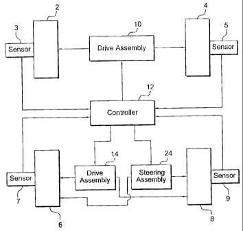
[0012] Referring to Fig. 1, the four wheel drive system according to the
invention will be described. The system is used to drive and steer a
bilaterally
symmetrical vehicle. Such vehicles include farm equipment, tractors, lawn
mowers,
and other types of heavy machinery which include front wheels 2, 4 and rear
wheels
6, 8. A first drive system 10 is connected with the front wheels to
independently
rotate each wheel in forward or reverse directions about horizontal axes to
propel the
vehicle. The wheels have a fixed vertical axis relative to the vehicle and
thus are not
steerable except that limited steering is achieved by rotating the wheels 2
and 4 at
different speeds or in different directions. A controller 12 is connected with
the first
drive system to control the delivery of drive power or force to the front
wheels via
the first drive system.
[0013] A second drive system 14 is connected with the controller and with
the rear wheels 6 and 8 in order to independently rotate each wheel in forward
or
reverse directions about horizontal axes to propel the vehicle. Thus, the
vehicle has
four wheel drive capability under control of the controller 12 which assists
the
vehicle in traversing unstable ground.
[0014] Unlike the front wheels, the rear wheels 6, 8 are steering wheels.
In
order to accommodate steering thereof, the rear wheels are connected with the
vehicle for rotation about a vertical axis. In Figs. 2 and 3 is shown one of
the rear
wheels 6 which has a horizontal axis H which passes through the center of the
axle
16 on which the wheel is mounted and a vertical axis V which passes through
the
center of a vertical shaft 18. The vertical shaft is connected at its lower
end with a
frame 20 which passes above and down the side of the wheel. The horizontal
axle
16 is connected with the lower end of the frame. As shown more particularly in
Fig.
3, the wheel vertical shaft 18 passes through the frame 22 of a vehicle and is
rotatable with respect to the frame. This allows the wheel 6 to be rotated
about its
vertical axis V in order to steer the vehicle. Preferably, the wheel is
rotatable
through 360 degrees. The other rear wheel 8 is connected in the same manner as
the
wheel 6 to be steerable as well.
CA 02661313 2010-12-31
6
[0015] A steering system or assembly 24 is connected between the
controller 12 and the rear wheels 6 and 8 as shown in Fig. 1. The steering
system
is operable to independently rotate the wheels about their vertical axes.
Because
the rear wheels are rotatable through 360 degrees, the vehicle has a zero
turning
radius which allows it to turn around within its length. Referring to Fig. 3,
the
steering system for each wheel includes a motor 26 which is operated by the
controller 12 to rotate the vertical shaft 18 to turn the associated steering
wheel 6.
The motor can be an electric motor, a hydraulic motor, or an air motor as will
be
appreciated by those of ordinary skill in the art. According to a preferred
embodiment of the invention as shown in Fig. 3, the motor 26 comprises a
hydraulic pump. The controller controls valves (not shown) between the pump 26
and the vertical shaft 18 to control the delivery of hydraulic fluid to the
shaft to
rotate the shaft in opposite directions. Thus each of the steerable rear
wheels 6, 8
includes a horizontal drive 14 for propulsion and a vertical drive assembly 24
for
steering.
[0016] Each wheel includes a conventional sensor 3, 5, 7, 9 connected
with the controller to provide feedback signals as is known in the art which
indicate the direction and speed of horizontal rotation of each wheel as well
as the
rotational position of the rear wheels with respect to their vertical axes.
The
feedback signals can be used to override certain inputs to the controller by
the
operator of the vehicle to prevent the vehicle from being driven in a
dangerous
manner. For example, as the forward speed of the vehicle increases, the
turning
radius of the vehicle is increased to prevent the vehicle from tipping over by
turning too sharply at high speed.
[0017] A preferred drive system for the front wheels of the vehicle is
shown
in Fig. 4. This drive system is disclosed in U.S. patent No. 6,957,731. The
driving
system of Fig. 4 includes a power source 102 connected with a power splitter
104
via a drive shaft 106. The power splitter includes output shafts 108 and 110,
which
are connected to the first differential clutches 112 and 114, respectively.
First
differentials 112 and 114 have a single input which receives power from the
output
shafts 108, 110 from the power splitter, and two outputs, which are connected
to
second differentials 130, 132 via their respective output shafts. More
particularly,
output shafts 134 and 136 connect first differential 112 to the second
differential
130, while output shafts 138 and 140 connect first differential 114 to second
differential 132. Output shafts 134, 138 rotate in a first direction, while
output
CA 02661313 2010-12-31
7
shafts 136, 140 rotate in the opposite direction. Second differentials 116,
118 have
two inputs and a single output. Because the splitter delivers the same output
to the
differential clutches, the drive system is bilaterally symmetrical.
[0018] Each second differential clutch has an output drive shaft 116, 118
connected with a wheel 2, 4. The operation of each differential clutch is
individually
controlled by braking devices 124, 126, 142, and 144. The braking devices may
be
of any conventional type including pumps or generators. Braking action from
one of
the braking devices slows or stops the rotation of the corresponding shaft
spinning in
a first direction and engages the differential clutch of the first
differential shaft with
which it is connected, thereby allowing power to be transmitted to the output
shaft
rotating in the opposite direction. The rotating shaft transmits power turning
the
other output shaft which is also connected to the second differential. Because
the
braking devices are controlled independently via the controller 12 by the
operator,
the amount of driving force applied to each wheel from the power source can be
controlled to propel the wheel in a forward or reverse direction as well as to
provide
coordinated steering of the vehicle.
[0019] For example, if braking elements 124, 126 are engaged, power from
the power source is transmitted to second differential clutches 130, 132 by
output
shafts 136 and 140, respectively, thereby facilitating reverse motion. If
braking
elements 142, 144 are engaged, power from the power source is transmitted to
second differential clutches 130, 132 by output shafts 134 and 138,
respectively,
thereby providing forward motion.
[0020] To execute a right turn, braking elements 142, 126 are engaged,
thereby causing power from the power source to transmit to second differential
clutches 130, 132 by output shafts 134 and 140, respectively, thereby
facilitating a
zero-radius turn to the right. A zero-radius left turn is accomplished by
engaging
braking elements 124 and 144.
[00211 The preferred drive and steering systems for each of the rear
steering wheels 6 and 8 will be described with reference to Fig. 5. The drive
system 14 for each steering wheel includes a first variable displacement pump
150
connected with the controller which feeds hydraulic fluid to a first hydraulic
motor
152 which in turn is connected with the horizontal axle 16 of one of the rear
wheels. The connection would be via the wheel frame 20. The steering system 24
for each rear steering wheel includes a second variable displacement pump 154
which feeds hydraulic fluid to a second hydraulic motor 156 which is connected
with the vertical axle 18 of the wheel under control of the controller. The
first
CA 02661313 2010-12-31
8
hydraulic motor 152 actuates the horizontal axle to drive the wheel forward or
backward. The second hydraulic motor 156 actuates the vertical axle to turn
the
wheel left or right. Feedback signals are sent from conventional sensors 15,
17 on
the horizontal 16 and vertical 18 axles, respectively, to the controller 12 as
is
known in the art.
100221 Vertical axis rotation is achieved by indexing the second
hydraulic
motor 156. An encoder sends a.signal to the controller 12 so that the
controller
knows the angle at which each of the rear wheels is pointing. With such an
arrangement, the rear wheels can rotate about their vertical axes to a much
greater
angle than traditional traction or steering wheels.
[00231 Hydraulic motors can also be used to independently drive the front
wheels 2 and 4 in place of the drive system shown in Fig. 4. The motors would
be
supplied by a variable displacement pump under control of the controller in a
manner similar to the horizontal axle drive system of Fig. 5 for the rear
wheels. In
addition, each of the drive and steering motors may comprise electric or
pneumatic
motors as is known in the art.
[0024] In operation, an operator can use a joystick, not shown, to
provide
input to the controller which is used to propel and steer the vehicle. If the
operator
pushes the joystick all the way to the left, the vehicle would sit still but
the rear
wheels will rotate about their vertical axes and would be pointed at 90
degrees to the
direction of the front wheels and also therefore 90 degrees to where the
machine is
facing. If the operator then moved the joystick forward, still holding it all
the way to
the left, the vehicle would begin making a very sharp left hand turn. The
right front
wheel would roll forward, and the left front wheel would roll backward, both
under
power. The rear wheels would drive forward, that is, they would push the rear
of the
vehicle to the right at a right angle to where the vehicle is facing. If the
operator then
pulls the joystick backwards, still with the joystick all the way to the left,
the left
front wheel 2 would be driven forward and the right front wheel 4 would be
driven
in reverse.
[0025] The rear wheels would not change relative to their vertical axes,
but
their horizontal rotation would be reversed. If the drive system for the front
wheels
is of the type shown in Fig. 4, the pumps which are used in place of brakes
can be
used to provide the hydraulic oil to drive the rear wheels. A valve is
integrated into
the system so that the oil goes in the proper direction
past the wheel motors on the rear wheels.
CA 02661313 2010-12-31
9
[0026] While the preferred forms and embodiments of the invention have
been illustrated and described, it will be apparent to those of ordinary skill
in the art
that various changes and modifications may be made without deviating from the
inventive concepts set forth above.