Note: Descriptions are shown in the official language in which they were submitted.
CA 02661327 2014-04-17
22949-397
1
"Method and device for treatment of liquid
materials based on organic waste products."
An aspect of the invention relates to a method and arrangement for the
treatment of liquid materials based on organic waste products, especially
sludge from
sewage disposal plants.
In particular, the treatment is carried out in order to provide high value
organic fertilizer products in which added nutrients are bound organically.
The
fertilizer product is intended to provide for desirable crop yields and to
replace the
use of mineral fertilizer. The current conventional mineral fertilizers
include easily
soluble nutrients, and were originally developed for being a supplement to
manure. In earlier times, most farms were supplied with manure from their own
farm animals. With the easily soluble nutrients that were brought in with the
mineral fertilizers, significantly improved crop yields were achieved the
short term.
A gradually increasing use of mineral fertilizers has exhausted the soil to an
extent
that has resulted in large uncultivable land areas. Moreover, the use of
mineral
fertilizers and eradicants has resulted in a significant run-off to rivers,
lakes and
oceans, which has destroyed or is threatening other life systems. In order to
stop
this unfortunate trend, several countries have introduced an environmental tax
on
mineral fertilizers in order to limit the use thereof. It is hence an object
of the
present invention to provide a method and arrangement that are able to improve
the provision of organic fertilizer products which, in a long term
perspective, may
fully or partially replace the use of mineral fertilizer.
Known processing plants for the conversion of sewage, for example, to
organic fertilizer products are based on the batchwise feeding of the material
into
a processing chamber in which chemicals are added. The addition of the
chemicals into the mass causes reactions to occur that effect the generation
of
heat and liquid vaporization, pH regulation and nitrogen elevation in the end
product. The thus chemically treated mass is then supplied with heat for
effecting
liquid vaporization in order to achieve the desired solids percent in the
final
product.
These prior art methods suffer from several disadvantages and drawbacks.
The batchwise treatment is hence not a very efficient solution. Moreover, the
CA 02661327 2014-04-17
22949-397
2
relatively high temperatures being used (generally well above 200 C) will
render
ineffective humic acids and other substances that are important for improving
the
soil.
Furthermore, when the reaction processes occur within the mass, the liquid
degasification will be impeded and generally diminish the results of the
reaction
treatments. Also, when applying extreme heat in the degasification/drying
process
and in the granulation process subsequent to the reaction treatment, the
temperature must be kept sufficiently low so that the valuable soil-improving
substances of the material are not lost. Various low temperature technology
processes exist that may be adapted for this purpose, but the properties of
the
material from the reaction treatment is also of vital importance for the
result of the
process.
The patent NO 302813, having the same inventor as the present
application, relates to a method and arrangement that enable a continuous
sludge
dehydration process and that don't require external heating of the sludge to
effect
the necessary vaporization, while at the same time the temperature is to be
kept
sufficiently low so that none of the valuable soil-improving substances of the
material are lost. The reaction processes are initiated when the materials are
direct shock treated by rotary processing means while falling down through the
vertical treatment chamber. Liquid and air are beaten out from the pores in
the
solid particles of the mass, forming compact, free particles having
unrestricted
degasification conditions. At the same time, the released liquid gets a
relatively
large surface and thereby excellent vaporization/degasification conditions
with a
cooling effect, acting to keep the temperature sufficiently low. At the same
time,
the heat developed in the chemical reactions and friction treatment is
sufficient to
provide for the desired vaporization. In such a continuous process, free
liquid
surrounding the particles will ensure_an adequate absorption of the supplied
heat
energy.
=
An aspect of the present invention is directed to an improvement of the
technology
described in NO 302813. It is, in particular, an aspect according to one
embodiment of the
present invention to increase the degree of reaction in the shock treatment by
the rotary
processing means during the movement of the material through the vertical
treatment
chambers, to thereby increase the degree of dehydration and nitrogen
CA 02661327 2014-04-17
22949-397
3
portion/nutrient content of the resulting fertilizer product while at the same
time the
use of chemicals such as sulphuric acid and ammonia may be reduced in that the
capture of added nutrients in the fertilizer product is significantly
increased.
According to another aspect of the invention, there is provided an improved
method
and arrangement for carrying out the last dehydration step.
According to another aspect of the invention, there is provided a
method for the treatment of material based on organic waste products, wherein
the
material is added and mixed with chemicals, during vaporization and
degasification of
liquid from the material to increase the solids content thereof, the material
being
continuously introduced at an upper part of a vertical mixing vessel; in which
the
material is subject to mixing, after which the material is passed on into a
reactor tank
for sulphuric acid treatment and at the same time, while sinking through the
sulphuric
acid treatment reactor tank, is exposed to an impact action from a row of
rotary
processing means disposed in the sulphuric acid reactor tank, after which the
material is passed on into a reactor tank for ammonia treatment and at the
same
time, while sinking through the ammonia treatment reactor tank, is exposed to
an
impact action from a row of rotary processing means disposed in the ammonia
treatment reactor tank, after which the material is finally passed on into a
drier in
which the material is dried until a desired solids content has been achieved,
wherein
arm-rings constituting said row of rotary processing means, move in a
counter-rotating manner.
According to another aspect of the invention, there is provided an
arrangement for the treatment of material based on organic waste products,
wherein
the material has been added and mixed with chemicals, the arrangement further
being configured for vaporization and degasification of liquid from the
material to
increase the solids content thereof, the arrangement comprising a vertical
mixing
vessel configured to mix the material, a reactor tank for sulphuric acid
treatment, the
sulphuric acid reactor tank further comprising a row of rotary processing
means
arranged in the sulphuric acid reactor tank, a reactor tank for ammonia
treatment, the
CA 02661327 2014-04-17
22949-397
3a
ammonia treatment reactor tank further comprising a row of rotary processing
means
arranged in the ammonia treatment reactor tank, the arrangement finally
comprising a
drier to dry the material to a desired solids content, wherein counter-
rotating
arm-rings comprise said row of rotary processing means.
In the following, aspects of the invention will be described in more detail
with reference to the attached drawings, in which:
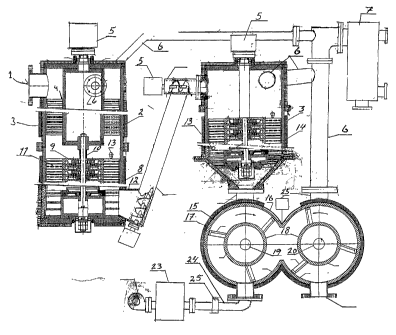
Fig. 1 shows a view of a possible embodiment of the present invention,
and
Fig. 2 shows a side view of a possible embodiment of the drier
according to the present invention.
The process according to the invention, as shown schematically in
fig. 1, comprises a number of process steps, of which the first step includes
feeding
biomass, in the form of sludge from sewage disposal plants and possibly other
organic waste products, for example, into a mixing vessel 1. The mixing vessel
1 may
be comprised of, for example, a cylindrical, thick-walled steel tank provided
with an
external electric heating loop, induction coil, water/gas borne heating loop
2, or the
like. Preferably, mixing vessel 1 includes an outer heat-insulating jacket 3.
Inside
mixing vessel 1, a number of rotors 4 are arranged, each comprising several
impact
arms, at several vertical levels. Rotors 4 may be driven by an electric or
hydraulic
motor 5, for example, possibly in combination with a cone belt or the like.
The
purposes of mixing vessel 1 are to mix the biomass into a homogenous mixture,
divide larger particles into small, dispersed particles, and to heat the
biomass using a
combination of friction treatment and supplied heat, to approx. 55 C, for
example.
From mixing vessel 1, exhaust gas is lead via an exhaust gas outlet stub 6 to
a
condenser 7, from which the condensate will be excellently suited for use as
fluid
fertilizer.
CA 02661327 2014-04-17
22949-397
3b
From mixing vessel 1, the preprocessed biomass will, by way of gravity,
fall directly down into a reactor tank 8 for sulphuric acid treatment. Said
sulphuric acid
treatment forms process step 2. Reactor tank 8, like mixing vessel 1, includes
a
cylindrical, thick-walled steel tank, and is, in the present exemplary
embodiment,
flange-connected to mixing vessel 1. Like mixing vessel 1, reactor tank 8
includes
CA 02661327 2009-02-20
WO 2008/030099 PCT/N02007/000293
4
an outer heat-insulating jacket 3, but as opposed to mixing vessel 1, reactor
tank 8
does not include a heating loop 2. Reactor tank 8 also includes rotors 9, with
the
rotors 9 of reactor tank 8 sharing or being connected to rotor shaft 10 of the
rotors
4 of mixing vessel 1. Rotors 9 are arranged to impact in alternately opposite
directions. This may be achieved in that rotor shaft 10 is provided with a
number
of arm-rings 11, with each arm-ring being provided with a number of impact
arms,
such as 4 on each arm-ring, for example. The first arm-ring may be mounted to
rotor shaft 10 in a spline connection, with the other arm-ring being rotated
in the
opposite rotational direction by means of a spline connection and planetary
transmission consisting of a sun gear, planet wheel, planet wheel receptacle
and
inner toothed ring gear, as well as a sprag-type unidirectional clutch between
the
rotor shaft 10 and planet wheel receptacle. All succeeding arm-rings may have
the
same rotational direction as the first arm-ring, or else (preferably) every
second
arm-ring may blow in the opposite direction, depending on the number of
is planetary transmissions being used and indeed also depending on the
number of
arm-rings 11 included in the reactor tank 8. The lowermost arm-ring is
specially
designed to hurl, by way of the centrifugal force, the biomass out through an
outlet
stub 12 of reactor tank 8 to the next process step 3.
It is understood that reactor tank 8 may also be fully or partially separate
from mixing vessel 1, in which case mixing vessel 1 could include an outlet
stub
through which the biomass would be discharged and passed on through a suitable
piping to reactor tank 8. It is also understood that it is not required that
mixing
vessel 1 and reactor tank 8 share the same rotor shaft 10, even though, at
least in
this example, this is considered practical.
Above arm-rings 11 in reactor tank 8, in the present exemplary
embodiment, a sulphuric acid inlet pipe 13 acid is provided. The purpose of
reactor tank 8 is to effect a reaction treatment of the biomass using
sulphuric acid
in order to 1) release water that is bound in microscopic cell bindings of the
biomass, 2) add further organically bound nutrient to the biomass, 3) friction
process the biomass in order to speed up the reactions and increase the
temperature, 4) lower the pH to a level between 0.5 and 2, for example, 5)
increase the temperature of the biomass due to the exothermal reaction to
approx.
85 C (preferably above approx. 70 ), for example, with the pH reduction and
CA 02661327 2009-02-20
WO 2008/030099 PCT/N02007/000293
heating providing a two-fold sanitation of the biomass, and 6) degasify water
up
through mixing vessel 1 and exhaust outlet stub 6 to the condenser 7.
It has turned out that in particular the counter-rotating movement of arm-
rings 11, together with the temperature increase due to the addition of
sulphuric
5 acid and the friction treatment, results in a beneficial short treatment
time in the
reactor tank. The counter-rotation of arm-rings 11, and hence of the biomass,
optimizes the mixing of sulphuric acid and the break-up of the cell bindings
of the
biomass, while at the same time the distribution of sulphuric acid in the
biomass
becomes more homogenous than if the arm-rings 11 were hitting in the same
io direction.
When the lowermost arm-ring, by way of the centrifugal force, has
discharged the biomass through an outlet stub 12 of reactor tank 8, the
biomass is
carried to a reactor tank 14 for ammonia treatment. This is process step 3.
The
biomass is transferred from reactor tank 8 to reactor tank 14 by rotary
feeding or
the like, for example. According to the present embodiment, reactor tank 14
also
includes a cylindrical, thick-walled steel tank having an outer heat-
insulating jacket
15. In principle, reactor tank 14 does not need a heating loop. Like sulphuric
acid
treatment reactor tank 8, reactor tank 14 includes counter-rotating rotors, an
outlet
stub for carrying exhaust gases to condenser 7, etc. Ammonia, in the form of
ammonia spirit, is fed into reactor tank 14 through a suitable nozzle located
above
the uppermost impact arm, or else ammonia gas is fed into reactor tank 14
through a suitable nozzle at the lower impact arm. The ammonia treatment
yields
a further degasification, with the exhaust gas being discharged through an
outlet
stub at the upper edge of the uppermost impact arm to condenser 7, in which
the
condensate forms fluid fertilizer.
The purpose of reactor tank 14 is to effect a reaction treatment of the
biomass using ammonia in order to 1) release water that is bound in
microscopic
cell bindings of the biomass, 2) add further organically bound nutrient to the
biomass, 3) friction process the biomass, 4) increase the pH to a value of
about 6
(a pH of between 5 to 8, preferably approx. 6), and 5) increase the
temperature of
the biomass due to the exothermal reaction to above 100 C (above 85 C,
preferably above 100 C), with the increased pH and heating providing a two-
fold
sanitation of the biomass. The biomass has now become a high-grade organically
CA 02661327 2009-02-20
WO 2008/030099 PCT/N02007/000293
6
bound fertilizer product.
Following process step 3, the biomass has a solids content of about 55-60
A. In order to effect a further drying of the biomass, the biomass is passed
on to a
drier 15. The drier constitutes process step 4. In the present embodiment, the
drier 15 includes two welded, thick-walled steel cylinders mounted in parallel
having a center distance equaling the cylinder diameter minus approx. 20
millimeter. The drier 15 includes an external electric heat loop, an induction
coil or
water/gas borne heating loop 16, as well as an outer heat-insulating jacket
17.
Each of the two weld-together, parallel, thick-walled steel cylinders forming
drier
15 includes several levels of counter-rotating rotors 18, each having a number
of,
such as three or four, for example, impact arms. The assembly of counter-
rotating
rotors is driven by two counter-rotating rotor shafts 19, 20 powered through a
transmission 21 or the like by a suitable motor 22, such as a flanged electric
motor, hydraulic motor, or the like.
Hot air fed in counterflow through drier 15 to the biomass. A hot air tap 23
heats air which is then fed through a hot air inlet stub 24. Inlet stub 24 is
provided
with a vibrating motor 25 imparting high frequency oscillations to the hot
air,
generally in the order of 20 kHz. The biomass is also put in vibration by
means of
a vibrating motor 25 mounted in connection with drier 15 at the center line of
biomass inlet stub 26. Advantageously, drier 15 may be tilted (e.g. by 10 ) so
that
gravity will urge the biomass through drier 15. Fig. 2 shows an exemplary
embodiment of drier 15 according to the present invention.
The purpose of drier 15 is to expel the remaining moisture from the
biomass and to bring the biomass to a solids level of e.g. approx. 85 A,
(between
70-99%, preferably approx. 85-90%). This is achieved by way of the friction
treatment, heating, and vibration. The combined effect of these actions
increases
the temperature and ensures that the water content of the biomass vaporizes,
speeding up the drying process significantly. The counter-rotating rotors 18
make
sure the biomass is made and remains homogenous and composed by fine
particles, with the fine particles providing for a maximum surface area
speeding up
the vaporization of the water. The applied vibration ensures that water drops
are
vaporized to form aerosols, with the air flow-through expelling the aerosols,
and
hence the moisture, from drier 15. In the absence of such applied vibrations,
the
CA 02661327 2009-02-20
WO 2008/030099 PCT/N02007/000293
7
drying process step 4 would be prohibitively time consuming. In practice, it
would
not be possible to achieve a sufficiently high level of solids in the end
product.
It is an important feature of the invention that the drying process is carried
out with a combination of hot air supply and vibration.
As mentioned above, the purpose of condenser 7 is to transition the
exhaust gases from said process steps to a liquid form, whereby the condensate
will form an excellent liquid fertilizer product.
The present process steps 1-4 with the subsequent reaction chambers and
friction treatment of the biomass have resulted in a significantly reduced
reaction
time as well as significantly improved and more reliable reaction products as
compared to the conventional batch treatment. With the additional provision of
counter-rotation of the impact arms used in each process step, this has lead
to a
significantly improved turbulent and homogenous biomass environment for the
following process steps. The turbulent and homogenous biomass environment
ensures that the sulphuric acid added into reaction tank 8 is more rapidly
taken up
and allowed to fully react with the biomass. Similarly, the turbulent and
homogenous biomass environment in reaction tank 15 ensures that the added
ammonia is more rapidly taken up and allowed to fully react with the biomass.
The
result is that a substantially higher content of important nutrients in the
end
product is achieved in a less amount of time and with the same or a reduced
amount of added sulphuric acid and ammonia.
= Also, tests has shown that the use of higher temperatures in the biomass
during the reaction treatment reduces the consumption of sulphuric acid and
ammonia, resulting in a reduced pH regulation as compared to biomass having
lower temperatures, that requires an extensive pH regulation in order to
achieve
the same result in terms of liquid release, nutrients supply, desired
sanitation to a
so-called edible product, as well as desired end product quality including
organically bound nutrients.
It is understood that the present invention may be configured in various
manners, and that the disclosed embodiment is only intended to serve as an
example. Several modifications will be possible. For example, the arrangement
may be constructed as a continuous high column, the reaction chamber design
may be varied, and the number of rotors may vary. Additionally, the
temperatures,
CA 02661327 2009-02-20
WO 2008/030099
PCT/N02007/000293
8
frequencies, pH levels, solids contents, etc. indicated above may be adjusted
as
necessary. Also, it would be possible to replace sulphuric acid with nitric
acid,
even though this has not yet given equally excellent results.