Note: Descriptions are shown in the official language in which they were submitted.
CA 02661499 2009-02-23
WO 2008/023191
PCT/GB2007/003234
AMPHIBIAN
The present invention relates to an amphibian and, in
particular, to an amphibian having a three wheel
configuration.
A number of road wheel and seating arrangement layouts
have been proposed and built for amphibians. The most
popular layout, as for road vehicles, is to have four wheels
and sit-in seating provided across the amphibian in one or
more rows. This convention provides stability and ease of
communication respectively. However, it also sets
constraints on the dimensions, weight, performance and
manoeuvrability of the amphibian.
Two wheeled amphibians are also known, for example,
from Buchanan (GB 2,254,831). The size of hull needed to
ensure flotation on water gives a bloated appearance to the
amphibian, reduces stability and manoeuvrability on road,
and hinders access to mechanical parts for servicing.
Indeed, such amphibians tend to be compromised both on land
and on water. For example, Buchanan provides extensible
bellows on both sides of his amphibian body, to act as
stabilizers at low speed on water.
Three wheeled road vehicles are known, the convention
being to have a single front wheel and two driven rear
wheels. This allows a small turning circle, and
uninterrupted space for passengers and/or goods at the rear
of the vehicle. However, this layout is notoriously
unstable on land. On the other hand, the three wheeled
Morgan sports cars, which had two wheels at the front and
CA 02661499 2009-02-23
WO 2008/023191
PCT/GB2007/003234
- 2 -
one at the back, are remembered with affection over fifty
years after going out of production.
Three wheeled amphibians are known, for example from
Grzech (US 5,690,046), who uses a single front wheel. The
two rear wheels are covered on water by complex hinged
panels, which may stop working if damaged in collisions or
if their mechanisms were clogged by water, or by fine
debris, e.g. sand. Salt water may of course lead to
corrosion. It is noted that Grzech does not provide a full
description of the operation of these covers. Grzech shows
hinged panels which are hinged in one dimension, but need to
be hinged in two dimensions.
Baker (WO 99/24273) discloses a three wheeled amphibian
whose wheels, including a single rear wheel, are not
retractable. The glazing, roof, and doors of Baker's
amphibian add weight, cost, and complexity, and enclose the
driver and passengers in a conventional sit-in vehicle
architecture. Similarly, the driver and passenger sit side-
by-side, meaning that the driver is offset from the
amphibian centre line. This in turn necessitates handed
steering, which increases complexity of production in a
small and fragmented niche market. When only the driver is
aboard, there are potential problems in amphibian handling
due to offset weight distribution. The side-by-side front
seating also sets a minimum width for the amphibian.
A further amphibian is disclosed by Maguire (US
6,505,694). Essentially, this is a snowmobile adapted to
float. It has two front wheels and a rear endless track
drive mounted on the centre line of the amphibian. Marine
CA 02661499 2014-12-10
60853-138
- 3 -
propulsion is effected by the track drive which is
retractable within the bodywork when the amphibian is on
water. Marine propulsion by track drives has been found to
be painfully slow even with exposed tracks; retracted tracks
are even less efficient. Maguire's amphibian is also
compromised by these tracks on hard surfaces. Track drives
limit speed and manoeuvrability on metalled roads. A hard
track made of steel will damage the road, a soft track will
be damaged by the road.. Maguire's amphibian will stress its
track particularly badly when turning, as shear loads in
opposite directions will be applied to opposite ends of each
cleat or lag.
In one aspect, the present invention provides an
amphibian for use in land and marine modes comprising:
a planing hull;
three wheel stations, two of the three wheel stations
being front wheel stations provided one on each side of and
in the front half of the amphibian, and the third wheel
station being a rear wheel station provided in a central
region in the rear half of the amphibian;
at least one wheel provided at each wheel station, each
wheel being movable between a protracted land mode position
and a retracted marine mode position;
land propulsion means to propel the amphibian on land
in the land mode, the land propulsion means comprising at
. 30 least one of the wheels; and
marine propulsion means to propel the amphibian on
water in the marine mode, the marine propulsion means
CA 02661499 2014-12-10
60853-138
- 4 -
comprising at least two impellers or propellers provided one
on each side of the rear wheel station.
=
In a second aspect, the present invention provides an
amphibian for use in land and marine modes comprising:
a planing hull;
three wheel stations, two of the three wheel stations
being front wheel stations provided one on each side of and
in the front half of the amphibian, and the third wheel
station being a rear wheel station provided in a central
region in the rear half of the amphibian;
at least one wheel provided at each wheel station, each
wheel being movable between a protracted land mode position
and a retracted marine mode position;
land propulsion means to propel the amphibian on land
in the land mode, the land propulsion means comprising at
least one of the wheels; and
marine propulsion means to propel the amphibian on
water in the marine mode, the marine propulsion means
comprising at least one impeller or propeller, wherein:
the land propulsion means is independent of the marine
propulsion means.
In another aspect, there is provided an amphibian for use
in land and marine modes comprising:
a planing hull;
at least three wheels arranged in a three wheeled
vehicle configuration, two of the wheels being front wheels
=
provided one on each side of and in the front half of the
amphibian, and a third wheel being a rear wheel provided in
a central region in the rear half of the amphibian, each
CA 02661499 2014-12-10
60853-138
- 5 -
wheel being movable between a protracted land mode position
and a retracted marine mode position;
land propulsion means to propel the amphibian on land
in the land mode, the land propulsion means comprising at
least one of the wheels; and
marine propulsion means to propel the amphibian on
water in the marine mode, the marine propulsion means
comprising at least one impeller or propeller, wherein:
the land propulsion means is independent of the marine
propulsion means.
In another aspect, there is provided an amphibian for use
in land and marine modes comprising:
a planing hull;
three wheels, two of the wheels being front wheels
provided one on each side of and in the front half of the
amphibian, and the third wheel being a rear wheel provided
in a central region in the rear half of the amphibian, each
wheel being movable between a protracted land mode position
and a retracted marine mode position;
land propulsion means to propel the amphibian on land
in the land mode, the land propulsion means comprising at
least one of the wheels; and
marine propulsion means to propel the amphibian on
water in the marine mode, the marine propulsion means
comprising at least one impeller or propeller, wherein:
the land propulsion means is independent of the marine
propulsion means.
In another aspect, there is provided an amphibian for use
in land and marine modes comprising:
a planing hull;
r
CA 02661499 2014-12-10
60853-138
- 6 -
three wheel stations; two of the three wheel stations
being front wheel stations provided one on each side of and
in the front half of the amphibian, and the third wheel
station being a rear wheel station provided in a central
region in the rear half of the amphibian;
at least one wheel provided at each wheel station, each
wheel being movable between a protracted land mode position
and a retracted marine mode position;
a prime mover which in the land mode of the amphibian
provides direct or indirect drive to at least one of the
wheels;
marine propulsion means to propel the amphibian on
water in the marine mode, the marine propulsion means
comprising at least two impellers or propellers provided one
on each side of the rear wheel station.
In another aspect, there is provided an amphibian for use
in land and marine modes comprising:
a planing hull;
three wheels, two of the three wheels being front
wheels provided one on each side of and in the front half of
the amphibian, and the third wheel being a rear wheel
provided in a central region in the rear half of the
amphibian, each wheel being movable between a protracted
land mode position and a retracted marine mode position;
land propulsion means to propel the amphibian on land
in the land mode, the land propulsion means comprising at
least one of the wheels; and
marine propulsion means to propel the amphibian on
water in the marine mode, the marine propulsion means
comprising at least two impellers or propellers provided one
on each side of the rear wheel station.
CA 02661499 2014-12-10
60853-138
- 7 -
In another aspect, there is provided an amphibian for use
in land and marine modes comprising:
a planing hull;
three wheels, two of the three wheels being front
wheels provided one on each side of and in the front half of
the amphibian, and the third wheel being a rear wheel
provided in a central region in the rear half of the
amphibian, each wheel being movable between a protracted
land mode position and a retracted marine mode position;
land propulsion means to propel the amphibian on land
in the land mode, the land propulsion means comprising at
least one of the wheels; and
marine propulsion means to propel the amphibian on
water in the marine mode, the marine propulsion means
comprising at least one impeller or propeller, wherein:
the land propulsion means is independent of the marine
propulsion means.
In another aspect, the present invention provides an
amphibian for use in land and marine modes comprising:
a planing hull;
three wheel stations, two of the three wheel stations
being front wheel stations provided one on each side of and
in the front half of the amphibian, and the third wheel
station being a rear wheel station provided in a central
region in the rear half of the amphibian;
at least one wheel provided at each wheel station, each
wheel being movable between a protracted land mode position
and a retracted marine mode position;
CA 02661499 2014-12-10
60853-138
- 8 -
land propulsion means to propel the amphibian on land
in the land mode, the land propulsion means comprising at
least one of the wheels; and =
marine propulsion means to propel the amphibian on
water in the marine mode, the marine propulsion means
comprising at least one impeller or propeller, wherein:
the marine propulsion means is driven independently of
the land propulsion means.
In another aspect, there is provided an amphibian for use
in land and marine modes comprising:
a planing hull;
three wheel stations, two of the three wheel stations
being front wheel stations provided one on each side of and
in the front half of the amphibian, and the third wheel
station being a rear wheel station provided in a central
region in the rear half of the amphibian;
at least one wheel provided at each wheel station, each
wheel being movable between a protracted land mode position
and a retracted marine mode position;
land propulsion means to propel the amphibian on land
in the land mode, the land propulsion means comprising at
least one of the wheels;
marine propulsion means to propel the amphibian on
water in the marine mode, the marine propulsion means
comprising at least one impeller or propeller; and
a prime mover, wherein:
the marine propulsion means is driven by the prime
mover independently of the land propulsion means.
In another aspect, there is provided an amphibian
comprising at least three retractable wheels, at
CA 02661499 2014-12-10
60853-138
=
- 9 -
least two of the retractable wheels being retractable about
an axis substantially parallel to, or offset by an angle a
of up to 40 degrees from, a longitudinal axis of the
amphibian, and at least one of the retractable wheels being
retractable about an axis substantially parallel to, or
offset by an angle p of up to 40 degrees from, a transverse
axis of the amphibian.
Thus, in some embodiments an amphibian is provided with
10. good handling on water and inherent stability on land. It is
capable of operation on land and on water with minimal
operational compromise on either medium.
The applicant has combined the benefits of two spaced
apart wheels at the front of the amphibian and a central
wheel at the rear to optimise on land performance, but which
is counter-intuitive to optimising performance on water due
to the inherent track width at the front of the amphibian,
with a narrowing pointed hull at the front provided between
the front wheels, which hull becomes wider rearwards along
its length to optimise on water performance, but which hull
is counter-intuitive to optimising on land performance due
to the shape of the hull suggesting a single central front
wheel and two spaced apart wheels at the rear.
Another aspect of the present disclosure provides a
powertrain for an amphibian. This provides a compact layout of a
powertrain for an amphibian.
For the avoidance of doubt, reference herein to a rider
or a driver means the person controlling the amphibian.
CA 02661499 2009-02-23
WO 2008/023191 PCT/GB2007/003234
- 10 -
Grzech describes a centrally mounted water jet unit,
which ejects water between the two rear wheels. The
disclosed water jet unit would be incompatible with a single
rear wheel, for packaging reasons.
Baker describes an amphibian propelled in water by
vanes attached to the rear wheel. The rear wheel must
remain immersed in order to thrust the amphibian forward.
This increases the drag of the amphibian in water, since
half of the wheel and tyre are always under the water when
the amphibian is operated in marine mode.
Grzech provides for retraction of a single front wheel
by long-travel hydraulic suspension forks, with road
steering disconnection by splines on the forks. This design
is not readily adaptable to a pair of front wheels.
Baker uses water skis which can be rotated beneath the
front wheels to allow planing on water. This prevents the
amphibian from leaning into turns on water, reducing
possible cornering speed.
Both Grzech (with articulated wheel covers) and Baker
(with mudguards rotating to become water skis) teach
covering of wheels over water. The mechanisms necessary to
move such covers can be difficult to maintain. Mechanisms
and, where used, electric motors are exposed to a number of
aggressive substances such as salt water and sand, which are
liable to erode, clog, corrode, or distort moving parts.
The operation of the covers may also be adversely affected
by distortion of the covers and/or their mechanisms
CA 02661499 2009-02-23
WO 2008/023191
PCT/GB2007/003234
=
- 11 -
resulting from collisions, even with minor obstacles such as
rocks under water. Furthermore, the covers may be visible
on the outside of the amphibian, and thus will need a class
"A" finish for marketing reasons. Such a high gloss finish
will be very vulnerable to scratching and chipping, leading
to rapid deterioration in the appearance of the amphibian.
Surprisingly, the present applicant has found in trials
of prototype amphibians that such covers are not necessary
to ensure good marine handling. Furthermore, exposed wheels
have the advantage that the tyres can act as fenders. The
tyres are especially effective in absorbing minor bumps if
the wheels are retracted at an angle to the vertical.
Preferred embodiments of the present invention will now
be described, by way of example only, with reference to the
accompanying drawings in which:
Figure 1 is a perspective view from above of an
amphibian according to a first embodiment of the present
invention, with the wheels protracted for use in land mode;
Figure 2 is a perspective view from below of the
amphibian of Figure 1;
Figure 3 is a front elevation view of the amphibian of
Figure 1;
Figure 4 is a side elevation view of the amphibian of
Figure 1;
Figure 5 is a rear end elevation view of the amphibian
of Figure 1;
Figure 6 is a top plan view of the amphibian of Figure
1;
Figure 7 is a bottom plan view of the amphibian of
Figure 1;
CA 02661499 2009-02-23
WO 2008/023191
PCT/GB2007/003234
- 12 -
Figure 8 is the same perspective view of the amphibian
of Figure 1, but with the wheels retracted for use in marine
mode;
Figures 9 to 14 correspond to the views shown in
Figures 2 to 7 save that the views shown in Figures 9 to 14
show the amphibian with the wheels retracted for use in
marine mode;
Figure 15 is a perspective view from above of an
amphibian according to a second embodiment of the present
invention, with the wheels protracted for use in land mode;
Figure 16 is a perspective view from below of the
amphibian of Figure 15;
Figure 17 is a front elevation view of the amphibian of
Figure 15;
Figure 18 is a side elevation view of the amphibian of
Figure 15;
Figure 19 is a rear end elevation view of the amphibian
of Figure 15;
Figure 20 is a top plan view of the amphibian of Figure
15;
Figure 21 is a bottom plan view of the amphibian of
Figure 15;
Figure 22 is the same front perspective view of the
amphibian of Figure 15, but with the wheels retracted for
use in marine mode;
Figures 23 to 28 correspond to the views shown in
Figures 16 to 21 save that the views shown in Figures 23 to
28 show the amphibian with the wheels retracted for use in
marine mode;
Figure 29 is a schematic perspective view from above of
a rolling chassis of the amphibian of Figures 1 to 28;
CA 02661499 2016-11-07
60853-138
- 13 -
Figure 30 is a schematic perspective view from above of
a powertrain layout and retractable rear wheel suspension
assembly of the amphibian of Figures 1 to 28;
Figure 31 is a schematic top plan view of the
powertrain layout of Figure 30;
Figure 32 is a schematic side elevation view of the
powertrain layout of Figure 30;
Figure 33 is a schematic side elevation view of an
amphibian according to a third embodiment of the present
invention, in a land mode operation state;
Figure 34 is a schematic side elevation view of the
amphibian of Figure 33, in a marine mode operation state;
Figure 35 is a schematic underneath plan view of the
amphibian of Figure 33, in a land mode operation state;
Figure 36 is a schematic rear elevation view of the
amphibian of Figure 33, in a land mode operation state;
Figure 37 is a schematic underneath plan view of an
amphibian and powertrain layout according to a fourth
embodiment of the present invention;
Figure 38 is a schematic simplified partial-cross-
sectional view of an amphibian according a fifth embodiment
of the present invention;
Figure 39 is a schematic partial-front view of an
amphibian according to a sixth embodiment of the present
invention, showing a wheel in a protracted vehicle-
supporting position;
Figure 40 is a schematic partial-front view of an
amphibian according to Figure 39, showing a wheel in a
retracted position;
Figure 41A is a schematic simplified partial cross-
sectional view of an amphibian according to an embodiment of
the present invention, having a step-down drive;
CA 02661499 2009-02-23
WO 2008/023191 PCT/GB2007/003234
- 14 -
Figure 41B is a schematic partial cross-sectional view
of the step-down drive of Figure 41A;
Figures 42A and 42B are schematic cross-sectional plan
views of portions of hulls of amphibians;
Figure 43 is a rear perspective view of a seventh
embodiment of amphibian according to the present invention;
Figure 44 is a schematic top plan view of an eighth
embodiment of amphibian according to the present invention;
and
Figure 45 is a schematic side elevation view of the
amphibian of Figure 44.
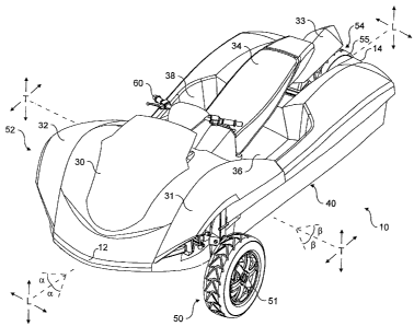
Referring first to Figures 1 to 7, there can be seen an
amphibian 10 in its land mode having a forward bow end 12
and a rear stern end 14.
The amphibian 10 has three wheel receiving stations 50,
52, 54. Two are front wheel stations 50, 52 provided one on
either side at the front of the amphibian 10, while the
third is a rear wheel station 54 provided in a central
region at the rear of the amphibian 10. At least one road
wheel 51, 53, 55 is provided at each wheel station 50, 52,
54. Each wheel 51, 53, 55 is connected to the remainder of
the amphibian 10 by any suitable wheel suspension system
which includes a wheel retraction mechanism for moving the
wheels 51, 53, 55 between a lowered state for land use and a
raised state for marine use. The front wheels 51 and 53 are
steerable and handlebars 60 are provided to enable steering
of these wheels. Alternatively, a steering wheel may be
employed in place of handlebars. The rear wheel 55 is
driven to propel the amphibian 10 on land. Alternatively,
or in addition, one or both front wheels 51, 53 may be
CA 02661499 2009-02-23
WO 2008/023191 PCT/GB2007/003234
- 15 -
driven (i.e. the amphibian may be one, two, three or all
wheel drive). Jet drive units 72, 74 (see Figure 2) provide
propulsion in marine use.
The structure of the amphibian 10 comprises an upper
deck section 30 and a lower hull section 40. The upper deck
structure 30 is sealed to the lower hull section 40 around a
peripheral planar edge 35 which is above the water line when
the amphibian 10 is fully displaced in water. The complete
upper deck section 30 is detachable from the lower hull
section 40 as a single unit, and/or as separate panels.
This permits ease of access to internal components of the
amphibian 10 for servicing, etc.
Air inlet openings (not shown) provide an entry for
cooling air (which may or may not be fan-assisted) for use
by the cooling systems of the amphibian 10. Air entrained
via these inlets is eventually exhausted via outlets (not
shown). Between the air inlets and air outlets, a dorade
system is installed to prevent the ingress of water. The
dorade system facilitates righting of the amphibian on water
by use of a labyrinthine air inlet passage system to prevent
the ingress of water should the amphibian 10 be inverted in
use in the marine mode.
Sit-astride seating 34 is provided for a driver and
passengers of the amphibian 10. Step through openings (not
shown) may be provided in the sit-astride seating 34 to aid
a rider/driver and/or passenger(s) getting on and off the
amphibian 10. Footwell areas 36, 38 are provided one on
either side of the sit-astride seating 34, each shrouded by
bodywork positioned laterally outside of the footwell areas
CA 02661499 2009-02-23
WO 2008/023191
PCT/GB2007/003234
- 16 -
36, 38 to provide protection. These footwell areas 36, 38
may be provided with means to bail automatically any water
shipped in use of the amphibian 10.
Front wheel arches 31, 32 and rear wheel arch 33 are
provided so as to afford protection from spray. An
instrument panel 62 is provided ahead of the steering
controls to convey relevant parameters of the amphibian 10
to the rider/driver. Additionally, rear view mirrors (not
shown) may be provided as a visual aid to the rider/driver.
Furthermore, navigation lights may also be provided within
or on the upper deck structure 30 in accordance with the
local legislative requirements.
The upper deck structure 30 forms an integral part of
the entire structure of the amphibian 10. It is a
structural component and not merely cladding. Typically it
will take the form of a composite structure (e.g. glass
fibres or carbon fibres set in resin) although any suitable
manufacturing method may be employed. Where localised areas
of strength are required in the upper deck structure 30,
extra layers or mats of fibres may be laid down during
manufacture. The deck 30 will be formed with localised
reinforced areas in order to provide a complete force
transmitting path extending around the amphibian 10 in a
complete circle in a plane orthogonal to a longitudinal axis
of the amphibian 10, in order to provide resistance to
torsional loads on the amphibian 10.
Referring in particular now to Figures 2 to 4 and 7,
the underside of the hull 40 can be seen extending from the
front bow section 12 to the rear stern section 14. Starting
CA 02661499 2009-02-23
WO 2008/023191
PCT/GB2007/003234
- 17 -
from the planar interface 35 with the upper deck section 30,
there is a wall 41 extending around a periphery of the
amphibian 10 down to a lower hull surface 42. The overall
displacement of the hull 40 provides stability when the
amphibian 10 is operated at high speed in marine mode, in
particular because of the volume of hull 40 spaced laterally
from the centre line of the amphibian 10. As such, when
cornering sharply, for example, an increase in righting
force is experienced as the angle of lean increases. The
bodywork provided laterally of the footwell areas 36, 38 in
particular provide righting forces spaced from the amphibian
10 centre line. Any or all such hull volumes can be
provided with buoyancy inserts to give residual buoyancy.
It will be appreciated that no cutouts are provided in
the hull 40 in the region of the front wheel stations 50,
52. Indeed, with reference in particular to Figure 14, it
will be appreciated that the only discontinuities 46, 48 and
49 in the hull are those provided at the rear of the hull 40
to accommodate the rear wheel station 54 and jet drives 72,
74. These discontinuities 46, 48 and 49 have little effect
on the performance of the hull 40. As such, it has been
possible to avoid the use of any cover device to reconstruct
the lines of the hull 40 when the wheel assemblies are
retracted for use in marine mode.
A vee-hull section 44 is formed in the central lower
surface 42 of the hull 40 and this can form or be provided
with a keel which runs from the bow 12 along the length of
the amphibian 10. Strakes or other hydrodynamic aids (not
shown) may be integrated in or provided on the hull 40. At
the rear of the hull 40, water intake areas 46, 48 are
CA 02661499 2009-02-23
WO 2008/023191
PCT/GB2007/003234
- 18 -
incorporated for the jet drive marine propulsion units 72,
74 of the amphibian 10. In addition, a recess 49 is
provided to accommodate the rear wheel 55.
The design of the hull 40 is critical in determining
the performance achieved when the amphibian 10 is operated
in the marine mode. The present applicant has spent
considerable time and effort in the design of the hull 40
which has resulted in a rather surprising shape as compared
to that usually expected for a planing water craft or
ampihiban. The hull 40 comprises a narrow uninterrupted (no
cutouts) bow section 43 having a dead rise angle of
substantially 23 degrees along its length, followed by a
widening rearward section 45 having a dead rise angle of
substantially 18 degrees along its length. This compares
with traditional planing hulls which start at the bow
section with a very steep dead rise angle and these dead
rise angles become more shallow along the length of the hull
towards the stern, typically ending at 5 degrees or less of
dead rise angle. Prior art amphibians have hulls provided
with substantial cutouts or discontinuities to accommodate
retractable wheel and suspension assemblies, these cutouts
or discontinuities being provided with hull covers or entire
slidable panels to reconstruct the lines of the hull for use
of the amphibian in marine mode.
Since the sit-on seating 34 of the amphibian 10 is
arranged longitudinally, the amphibian 10 is narrower than a
passenger car. Aligning the engine longitudinally along the
amphibian gives a body shape which is narrower in beam and
deeper. Rather than adopting the flat planing hull common
in the prior art, the applicant has adopted a greater dead
CA 02661499 2016-11-07
60853-138
- 19 -
rise angle for agile marine handling
accepting that this gives a need for a suspension with a lot
of travel to give adequate ground clearance on land.
Whereas before amphibians such as that of Grzech strove
to keep the track width of the wheels within the beam of the
amphibian, the applicant has realised that better land mode
operation can be achieved if the track width of the front
wheels 51, 53 of the amphibian 10 amphibian is greater than
the beam of the hull 40. The approach adopted by the
applicant does mean that wheels must be retracted through a
large angle in order to be clear of the amphibian waterline
in marine use, but the strategy does provide for an amphibian
capable both on land and on water.
In some embodiments, even with the small footprint of the hull 40 of the
amphibian 10, the hull design 40 is capable of propelling
the amphibian 10 up onto the plane with little difficulty in
fast time periods. Furthermore, on-water performance of the
amphibian 10 is not compromised and adequate ground
clearance is available when operating the amphibian 10 in
land mode.
The amphibian 10 has an overall length in the range of
from 3.600m to 4.200m, more preferably in the range of
3.800m to 4.050m, most preferably of substantially 3.950m,
an overall width in the range of from 1.730m to 2.000m, more
preferably in the range of 1.800m to 1.900m, most preferably
of substantially 1.850m, and an overall height in the range
of from 1.200m to 2.000m, more preferably in the range of
1.300m to 1.500m, most preferably of substantially 1.400m.
The wheelbase length of the amphibian 10 is in the range of
CA 02661499 2009-02-23
WO 2008/023191
PCT/GB2007/003234
- 20 -
from 2.300m to 3.700m, more preferably in the range of
2.400m to 3.000m, most preferably substantially 2.580m and
the track width of the front wheels 51, 53 is in the range
of from 1.400m to 1.900m, more preferably in the range of
1.600 to 1.700, most preferably substantially 1.655m. The
length of the hull 40 is in the range of from 3.000m to
4.200m, more preferably in the range of 3.300m to 3.900m,
most preferably substantially 3.600m. The maximum beam of
the hull 40 is in the range of from 1.100m to 2.000m, more
preferably in the range of 1.200m to 1.600m, most preferably
substantially 1.380m, and beam of the hull 40 between the
front wheels 51, 53 in the front region 43 is less than the
track width.
Referring now to Figures 8 to 14, these Figures
correspond to the views shown in Figures 1 to 7
respectively, save that each shows the amphibian 10 with its
wheels retracted for use in marine mode.
Referring next to Figures 15 to 28, there is shown a
second embodiment of amphibian 10 according to the present
invention. This second embodiment is broadly similar to the
first, save that it is a smaller scale version and comprises
a 'mudguard' type design of wheel arch for front wheel
arches 31', 32'. Like reference numerals designate like
components throughout. The hull 40 comprises a narrow
uninterrupted (no cutouts) bow section 43 having a dead rise
angle of substantially 16 degrees along its length, followed
by a widening rearward section 45 having a dead rise angle
of substantially 12 degrees along its length.
CA 02661499 2009-02-23
WO 2008/023191 PCT/GB2007/003234
- 21 -
The amphibian 10 has an overall length in the range of
from 2.700m to 3.800m, more preferably in the range of
3.000m to 3.600m, most preferably of substantially 3.323m,
an overall width in the range of from 1.200m to 1.800m, more
preferably in the range of 1.400m to 1.700m, most preferably
of substantially 1.600m, and an overall height in the range
of from 1.100m to 1.700m, more preferably in the range of
1.300m to 1.500m, most preferably of substantially 1.400m.
The wheelbase length of the amphibian 10 is in the range of
from 1.500m to 3.000m, more preferably in the range of
1.900m to 2.600m, most preferably substantially 2.330m and
the track width of the front wheels 51, 53 is in the range
of from 1.000m to 1.800m, more preferably in the range of
1.200m to 1.600m, most preferably substantially 1.430m. The
length of the hull 40 is in the range of from 2.400m to
3.600m, more preferably in the range of 2.700m to 3.300m,
most preferably substantially 3.000m. The maximum beam of
the hull 40 is in the range of from 0.900m to 1.500m, more
preferably in the range of 1.050m to 1.350m, most preferably
substantially 1.200m, and beam of the hull 40 between the
front wheels 51, 53 in the front region 43 is less than the
track width.
Referring now to Figure 29, there is illustrated,
schematically, a rolling chassis showing certain internal
components of the amphibian 10. A prime mover 80 can be
seen which is a multi-cylinder internal combustion engine.
Alternatively, any prime mover 80 such as electric,
hydraulic, pneumatic, hybrid or otherwise may be
beneficially employed. Wheel suspension and retraction
assemblies, powertrain, driveline and transmission
CA 02661499 2009-02-23
WO 2008/023191
PCT/GB2007/003234
- 22 -
components can be seen, and these are more fully described
below with reference also to Figures 30 to 32.
The powertrain comprises an output shaft 81 leading
drive from the engine 80 via a torsional damper 82 to a
driveshaft 83. Driveshaft 83 provides drive, via a forward-
neutral-reverse gearbox 85, continuously variable
transmission (CVT) 90 (see pulleys 91, 92) and reduction
drive 86, to a land mode output shaft 94. Land mode output
shaft 94 relays drive via a bevel gear set (not shown)
located in the rear wheel hub 413 to the rear wheel 55
during land use of the amphibian 10. Driveshaft 83 also
provides drive, via a belt drive system 100, to two marine
mode output shafts 102, 104. Belt drive system 100
comprises an input/driver toothed wheel 102, two
output/driven toothed wheels 104, 106 and a toothed belt
108. Marine mode output shafts 102, 104 relay drive to the
jet drive units 72, 74 during marine (and, optionally, land)
use of the amphibian 10. The jet drive units 72, 74 may be
permanently connected to the engine 80 to be driven thereby
at all times, whilst the rear wheel 55 is driven (connected
to the engine 80) only in its lowered (protracted) land use
position. The forward-neutral-reverse gearbox 85, CVT
transmission 90, reduction drive 86 and belt drive system
100 could of course be replaced in other embodiments by a
conventional automatic gearbox or a manual gearbox, or other
powertrain and/or transmission systems and arrangements, as
required.
Steering input is from handlebars 60. Various
mechanisms may be used to transfer movement from the
handlebars 60 to front steered wheels 51, 53. For example,
CA 02661499 2009-02-23
WO 2008/023191
PCT/GB2007/003234
- 23 -
the applicant's co-pending application published as US
2006/0178,058 Al discloses a steering system for a small
amphibian with handlebars, wherein road steering is
automatically disengaged as the retractable suspension is
retracted for use of the amphibian on water. However, this
is essentially a cam-operated steering system, without
gearing. If steering loads are sufficiently high that
gearing and power assistance are required, a steering system
according to the applicant's patent GB 2,400,082B may be
used. This patent discloses an adaptation of a power-
assisted rack and pinion automotive steering system to an
amphibian, arranged such that the power assistance also
applies to marine steering. This is helpful in damping out
the water feedback forces on the jet steering nozzle or
nozzles which might otherwise cause painful and/or
irritating feedback to the rider through the steering
control.
The seating 34 in the amphibian 10 is provided
substantially above the amphibian powertrain, with the
handlebars 60 located in the front half of the length of the
amphibian. This gives a good driving position for both
marine and land use.
The front left-hand wheel suspension and retraction
assembly 64 (the front right-hand, partially shown,
corresponds) and rear wheel suspension and retraction
assembly 400 are also shown in Figure 29. Spring and damper
assemblies are provided for each of wheels 51, 53, 55.
Retraction actuators 65 and 430 retract and extend these
wheel suspensions from their lowered positions (as is shown
in Figure 29) to their raised positions, while spring and
CA 02661499 2009-02-23
WO 2008/023191
PCT/GB2007/003234
- 24 -
damper units 66 and 402, 404 cater for normal suspension
movement. Where actuator rams 65 and 430 are hydraulic,
hydraulic fluid may be provided by a pump (not shown)
powered by the engine 80.
A fuller description of the rear assembly follows
immediately below (with reference to Figure 30) and, of the
front assemblies, follows later (with reference to Figures
38 to 42B). However, it is to be noted that these are only
examples of retractable suspensions which may be used.
Referring to Figure 30, the retractable rear suspension
400 can be seen to comprise a coil spring 402 and a
telescopic damper or shock absorber 404. First and second
ends of damper 404 are pivoted to the amphibian 10 at pivots
406 and 408 respectively. Pivot 408 is mounted on a cross
beam 410 which is part of a trailing arm assembly comprising
two front angled arms 411 and two rear angled arms 412, one
each provided on either side of rear wheel 55, and a forward
trailing arm 414. In normal bump and rebound movement, the
trailing arm assembly will pivot around the pivot 416 at the
front of the trailing arm assembly, compressing and
extending spring 402 and damper 404 to give conventional
damped suspension movement.
Upper pivot mounting 406 is mounted to retraction arm
420, which is in turn mounted at pivot 422 to bracket 424,
which is firmly mounted to the frame (not shown) of the
amphibian 10. A retraction ram 430 is mounted to bracket
424 at pivot mount 426, and to retraction arm 420 at pivot
point 428. When ram 430 is actuated to retract, arm 420 is
rotated forwards, pulling damper 404 forward and up. This
CA 02661499 2016-11-07
60853-138
- 25 -
in turn lifts arms 412 and thus the rear wheel 55 and
trailing arm assembly until the rear wheel 55 is fully
retracted. This movement is reversed for protraction of the
wheel 55 when the amphibian 10 returns to land.
This mechanism is essentially a simplified version of
the retractable suspension disclosed in the applicant's co-
pending application published as US 2006/0234,567A1, and
shares its advantages in that off-the-shelf coil springs and
telescopic damper valves may be used to tune and adjust the
ride and handling of the amphibian 10 as required.
Although a hydraulic ram is shown as the actuator for
the retractable suspension, other actuators powered by
compressed air or electricity could be used instead, as
required.
It will be appreciated that the above wheel suspension
and retraction assembly mechanisms described above are given
by way of example only, and any suitable alternative may be
beneficially employed. Alternative mechanisms which may be
used or adapted for suspension and retraction are described in
the applicant's patents and patent applications, such as US
Re. 36,901; US 6,886,83782; US 6,945,83282; US 6,994,35882;
WO 04/039,613A1; US 7,234,98282; and US 2006/0,234,567A1,
for example.
The powertrain components illustrated in Figures 29 to
32, i.e. the engine 80 and transmission are built up on a
frame platform which is then connected to the hull 40. This
gives considerable advantage for ease of manufacture.
Indeed it is envisaged that a chassis could be constructed
CA 02661499 2009-02-23
WO 2008/023191
PCT/GB2007/003234
- 26 -
with a frame supporting all of the wheel suspension
components, the wheel steering mechanism, the wheel
retraction mechanism, the engine and the transmission. This
would considerably aid construction and repair. This is
illustrated in Figure 29 where a rolling chassis of the
amphibian can be seen stripped of the surrounding hull and
deck sections. In Figure 29 there can be seen the engine,
the transmission as well as the suspension assemblies for
the front and rear wheels, all mounted to a common
supporting structure.
A radiator (not shown) located at the front of the
amphibian will cool the amphibian's engine, at least in land
use. The amphibian's engine can also be cooled by a
water/water heat exchanger (not shown) in marine use, with
water being drawn from beneath the amphibian to cool water
used by the engine cooling system.
Referring next to Figures 33 to 36, there is shown an
amphibian 310 according to a third embodiment of the present
invention. The amphibian 310 may include any or all of the
features described above, in any combination, with the
following particular features.
The amphibian 310 comprises a body 312 joined to a hull
314 at joint line 313, hence being a buoyant vessel, having
a pair of front wheels 320 and a single rear wheel 322. It
can be seen from Figure 36 in particular that hull 314 has a
vee-shaped cross-section, to enable both planing and good
handling on water.
CA 02661499 2014-12-10
60853-138
- 27 -
The amphibian 310 includes a prime mover 316, which may
be an internal combustion engine or a similar power source,
to provide power through a transmission 318 to the rear
wheel 322. Alternatively, the prime mover may power the
front wheels 320 only, or may power the front wheels 320 and
rear wheel 322.
The front wheels 320 are connected to the body 312 by
suspension 324, and covered by mudguards 326. These guards
may be fixed to the body or to the wheel suspensions by
brackets (not shown). The rear wheel 322 is connected to
the body 312 by a trailing arm 326, which provides
suspension for the rear wheel. The trailing arm may be
double-sided as shown, or single-sided.
The rear wheel 322 and front wheels 320 are retractable
by means of retraction mechanisms. The retraction
mechanisms for the front wheels may be as described in US
Patent No. Re. 36,901. The front wheel retraction mechanisms acts
on the suspension mechanisms to allow retraction and protraction
of the wheels 320.
The front wheel retraction mechanisms are operable to
raise the front wheels 320 by rotation about axes
substantially parallel to a longitudinal axis of the body.
Such axes are substantially horizontal when the amphibian is
level. The front wheels 320 are retractable above the
waterline when the amphibian is in a water mode.
The rear wheel retraction mechanism is operable to
raise the rear wheel 322 substantially vertically upwardly
CA 02661499 2009-02-23
WO 2008/023191 PCT/GB2007/003234
- 28 -
into the body 312. The rear wheel 322 is retractable above
the waterline when the amphibian is in a marine mode. One
or more struts according to US 6,886,837 B2 may be used to
retract and protract arm 328.
The front wheels 320 can be steered to provide
amphibian steering. Amphibian steering is controlled by
handlebars 334 linked to the front wheels 320.
Alternatively, the handlebars may be linked to the rear
wheel 322, or to both the front wheels 320 and rear wheel
322. A seat 332 is located on the body 312 to support a
rider of the amphibian 310, in a position facing forwardly
and within reach of the handlebars 334. The seat 332 and
body 312 allow the rider to sit along a central longitudinal
axis of the amphibian 310, with the rider's legs on either
side of the body 312. The driver is thus sitting astride
the body. Preferably, the seat 332 is dimensioned to allow
a passenger who can sit directly behind the driver on the
seat 332. The passenger would also sit centrally on the
amphibian 310, astride the body 312.
Figures 33 and 34 show that the body 330 is provided
with a front fender 336 at a front end of the amphibian, and
a rear fender 338 at a rear end of the amphibian.
Headlights 340 for use on land and marine lights 342 for use
on water are provided at the front end of the amphibian. A
combination tail light unit 348 is provided at the rear end
of the amphibian. This may incorporate a CHMSL (Centre High
Mounted Stop Light), where this is required by legislation.
Rear view mirrors 346 and a windscreen 344 are provided
on the body 312. Left and right footwells 350, 352 are
CA 02661499 2009-02-23
WO 2008/023191
PCT/GB2007/003234
- 29 -
provided on the body 312, for the rider and passenger to
rest their feet. The footwells have drains 354.
With reference to Figures 33 and 35, a hull 314 is
formed on the underside of the body 312. The prime mover
provides power to a marine propulsion unit. The marine
propulsion unit may be a water jet unit 360, or any other
form of marine propulsion. The water jet unit 360 is
preferably positioned on a central longitudinal axis of the
amphibian 310. The water jet unit 360 is preferably
positioned forward of the rear wheel. The water jet unit
has a jet intake 362, for drawing water into the jet unit; a
driveshaft 364 from transmission 318; an impeller section
366; and a jet nozzle 368, through which water is expelled
to provide propulsion.
At least one deflector 370 may be provided in order to
divert accelerated water from the jet nozzle 368 away from
the rear wheel 322 when the rear wheel is in a protracted
position. This will occur when the amphibian first enters
the water, when the water jet unit will provide propulsion
and the rear wheel 322 is yet to be retracted. The
deflectors 370 form a chevron shape in plan view with the
apex facing the jet nozzle 368, in order to divert water
either side of the rear wheel 322.
The deflectors 370 are located directly behind the jet
nozzle 368, and are attached to the trailing arm 328.
Hence, when the rear wheel 322 is fully retracted, the
deflectors 370 are clear of water expelled from the jet
nozzle 368. Ducts 372 and 374 may be provided to deflect
water rearwards. The exits from these ducts may be in the
CA 02661499 2009-02-23
WO 2008/023191
PCT/GB2007/003234
- 30 -
sides of the body, as shown, or more productively, in the
transom. Alternatively, upstanding and substantially
vertical walls (not shown) may be joined to the outer edges
of trailing arm 328, to deflect water rearwards along both
sides of rear wheel 322.
Figure 34 shows the amphibian 310 in a marine mode.
The front wheels 320 have been retracted by rotation above
the waterline. The rear wheel 322 has also been retracted
above the waterline. The wheels 320, 322 comprises tyres
376, 378 around their periphery. The front tyres 376 can
act as fenders when the wheels are retracted, to absorb
minor impacts to the amphibian on water.
The rear wheel 322 is not provided with any cover on an
underside when retracted. The underside of the rear wheel
322 is therefore exposed to water in the retracted position.
The front wheels 320 are similarly not provided with a
cover, and so are exposed to water when the wheels 320 are
retracted.
It may be found convenient for rear wheel 322 and tyre
378 to be exposed above the rear bodywork when retracted, as
shown in Figure 34. However, this requires a gap in the
bodywork, which may give rise to excess spray on wet roads.
Figure 36 shows a lid 380 which may be connected to trailing
arm 328 by a linkage (not shown) to lift it out of the way
as the wheel is retracted. Unlike the linkages described
above with reference to prior art, this linkage could be
very simple - possibly just a straight prop - and would be
well above the water line, and thus relatively immune to the
hazards of a marine environment.
CA 02661499 2009-02-23
WO 2008/023191 PCT/GB2007/003234
- 31 -
Alternatively, a "mud flap" type spray guard (not
shown) could be mounted to hull 314 near to rear fender 338.
This could be retracted automatically on water by a linkage
to the trailing arm. In this case, however, the linkage may
be partly located below the water line; and would therefore
have to be designed carefully to ensure durability.
Area 382 behind seat 332 may be used to provide either
an open, or a closed and waterproof storage area (not
shown). It could also be used to provide a fuel filler neck
and opening (not shown), depending on the location of the
amphibian fuel tank (not shown).
A fourth embodiment of an amphibian 910 and powertrain
according to the present invention will now described, with
reference to Figure 37. The amphibian 910 may include any
or all of the features described above, in any combination,
with the following particular features.
The amphibian 910 is a light weight version of the
amphibian 310, and is intended to carry one person, being
the rider. The amphibian 910 comprises a body 930 being a
buoyant vessel, and has two front wheels 920 and a single
rear wheel 922. The front wheels 920 and rear wheel 922 are
retractable by means of retraction mechanisms (not shown).
The rider sits on a seat astride the body 930 of the
amphibian 910, with the rider's legs on either side at least
part of the body 930. The seat is aligned with a central
longitudinal axis of the body 930. The seat and body 930
may be configured to support only one person, i.e. the seat
CA 02661499 2009-02-23
WO 2008/023191
PCT/GB2007/003234
- 32 -
is dimensioned only to support the rider and not a
passenger.
The amphibian 910 in a land mode may be front wheel
drive only. The rear wheel 922 is not driven in the
embodiment shown in Figure 37.
In a water mode, a water jet unit 960 can propel the
amphibian 910. The water jet unit 960 has a jet intake for
drawing water into the jet unit. The water is expelled from
a jet nozzle to provide propulsion. The water jet unit 960
and/or nozzle may be spaced apart from a central
longitudinal axis of the amphibian 910. Alternatively, the
water jet unit 960 and/or nozzle may be located on a central
longitudinal axis of the amphibian 910.
Alternatively, the water jet unit may have two nozzles
located either side of the rear wheel. The two nozzles may
be connected to a single water jet unit, or may be connected
one each to two separate water jet units.
A prime mover 916 and transmission 918 are located
between the front wheels and the rear wheel. Transmission
918 may be a continuously variable transmission (CVT). The
prime mover 916 may be a transversely mounted internal
combustion engine. Thus, the crankshaft axis extends
sideways. The prime mover 916 is connected to the front
wheels by a forwardly extending driveshaft 921 to a
differential 923, the differential 923 being linked to the
wheels in a known manner.
CA 02661499 2009-02-23
WO 2008/023191 PCT/GB2007/003234
- 33 -
The transmission 918 is connected to the water jet unit
960 by a jet driveshaft 961. The jet driveshaft 961 extends
rearwardly of the transmission 918. Since the driveshaft
921 and jet driveshaft 961 extend in opposite directions,
there is no interference between the two driveshafts. The
driveshaft 921 and jet driveshaft 961 extend substantially
parallel to the longitudinal axis of the body. This
drivetrain arrangement thus offers packaging advantages, as
it places the land drive train at the opposite end of the
amphibian to the marine drive train, so that they do not
conflict with each other spatially.
Front wheel drive may result in difficulties in leaving
water on muddy banks, due to rearward weight transfer.
However, the amphibian 110 may leave water on prepared, hard
surface slipways. The front wheel drive brings an
unexpected advantage, in that it offers a familiar "feel" to
riders who have become accustomed to driven front wheels in
road cars.
Pontoons 973 extend either side of the rear wheel 922.
The pontoons 973 are buoyant to improve the buoyancy of the
amphibian. The water jet unit 960 may be located in one of
the pontoons 973. An output nozzle of the water jet unit
may extend from one of the pontoons. In the embodiment of
two nozzles, one nozzle may extend from each pontoon. The
two nozzles may be connected to a single water jet unit.
Alternatively, each nozzle may be connected to a separate
water jet unit. One water jet unit may be located in each
pontoon.
CA 02661499 2009-02-23
WO 2008/023191 PCT/GB2007/003234
- 34 -
The water jet unit(s) 960 and/or output nozzle(s) may
be located adjacent to the pontoon(s).
The water jet unit 960 may be located substantially
alongside the rear wheel 922. The water jet unit 960
extends substantially parallel to the plane of the rear
wheel 922. Alternatively, the water jet unit 960 may be
located substantially ahead of the rear wheel 922, or
substantially rearward of the rear wheel 922.
The wheels 920, 922 are connected to the body 930 by
means of suspension (not shown). The suspension may be
arranged to allow the body 930 to lean from side-to-side,
i.e. about a longitudinal axis of the body. The body 930
can lean inwardly into corners in a similar manner to a
conventional motorcycle. The ability of the body 930 to
lean improves the cornering ability of the amphibian 910 on
land.
The amphibian 910 may be provided with lights, a
registration plate and any other means necessary to allow it
to be road legal.
Referring next to Figures 38 to 425, there are shown
amphibians 1001 according to fifth and sixth embodiments of
the present invention. The amphibian 1001 may include any
or all of the features described above, in any combination,
with the following particular features.
Amphibians should be well-suited for transporting
occupants on both land and water equally efficiently.
However, it will be understood from the prior art that most
CA 02661499 2009-02-23
WO 2008/023191
PCT/GB2007/003234
- 35 -
amphibians are more suited for transporting occupants on
either land or water, rather than both.
In order to provide good speed and manoeuvrability on
land, suspension arms, drive shafts and wheels are often
located at lower regions of the amphibian, often protruding
directly from a hull section of the amphibian and/or parts
of the amphibian that would be submerged during use on
water. Further, even though retractable suspension has been
described in the prior art, the suspension, drive shaft
and/or wheel - in the retracted position - is often left
exposed to water, when in use on water. Further, cut-out
portions or other abnormalities to the shape of the hull may
be provided in the hull section of the amphibian to
accommodate the suspension apparatus, drive shaft or wheel,
when the wheel is in either of the retracted or protracted,
vehicle-supporting positions. The protracted position would
be with the wheels in place for use of the amphibian on
land. Whilst the prior art designs provide hulls that are
buoyant and water-tight, a significant disadvantage is also
found in that they often have cut-outs, abnormalities,
and/or parts of the suspension apparatus, drive shaft or
wheel that are submerged and/or simply contactable by water
- even when retracted - in use of the amphibian on water.
This clearly alters the hydrodynamics of the hull section of
the amphibian, making the amphibian perform less-well on
water - especially if the cut-outs, abnormalities, and/or
parts of the suspension apparatus, drive shaft or wheel are
located in the planing surface of the hull. In particular,
large cut-outs for locating retracted wheels can have a
great impact on the speed and manoeuvrability of the
amphibian in use on water. For example, the amphibian may
CA 02661499 2016-11-07
60853-138
- 36 -
tend to "dig-in" at the back of an open wheel arch when
turning on water.
The present disclosure provides, in a further aspect, an
amphibian for use on land and water, comprising:
a hull having a planing surface which contacts water
when the amphibian is planing on water;
at least one retractable suspension apparatus which is
movable from a vehicle supporting position to a retracted
position; wherein
the retractable suspension apparatus comprises for each
wheel upper and lower suspension arms that are pivotably
connected at inboard ends to a support structure within the
hull and are pivotably connected at outboard ends with a
suspension upright, the upper suspension arm being pivotably
connected to the suspension upright by a first, upper pivot
connection and the lower suspension arm being pivotably
connected to the suspension upright by a second, lower pivot
connection;
the suspension upright extends from the second
connection, in a direction away from the first connection to
a wheel hub mount location at which the wheel hub is
rotatably mounted on the suspension upright at a location
remote from the first and second pivot connections;
the suspension upright when deployed in land use
extends externally of the hull across an outer face and/or a
side face of the planing surface; and
the lower suspension arm remains above a top of the
planing surface throughout use of the amphibian on land.
CA 02661499 2009-02-23
WO 2008/023191 PCT/GB2007/003234
- 37 -
Preferably, the suspension arms extend from within the
hull over an outer edge of the hull.
Most preferably, the wheel hub is located a distance
from the second connection at least equivalent to the
distance between first and second connections. Further, the
hub may be located at least around 5cm, 10cm, 15cm or 20cm
from the second connection.
Preferably, the wheel hub is rotatably mounted on the
suspension upright at a distal end of the suspension
upright.
The wheel hub is, preferably, driven to rotate by a
transmission relaying drive from a prime mover of the
amphibian. The transmission may have a step-down drive
section in which drive is taken from a location at or above
the lower pivot point and is relayed along or alongside the
suspension upright to the driven wheel hub.
Alternatively, the wheel hub may be driven by a hub
motor. Preferably, the hub motor is a hydraulic motor or an
electric motor.
Most preferably, the hull is a vee hull.
The amphibian may comprise a spring and damper assembly
connected between one of the suspension arms and the support
structure.
Preferably, the amphibian comprises a retractable and
extendable actuator operable to move the retractable
suspension apparatus from the vehicle supporting position to
the retracted position and vice versa. Further preferably,
the actuator is also operable to vary ground clearance by
varying the suspension height.
The support structure, preferably, comprises a
rotatable support arm which is pivotally mounted at one end
to a fixed part of the support structure and to which is
CA 02661499 2016-11-07
60853-138
- 38 -
pivotally connected the actuator, the actuator being
pivotally connected at one end to the support arm and being
pivotally connected at the other end to a fixed part of the
support structure, a/the spring and damper assembly being
pivotally connected at one end to the rotatable support arm
and at the other end to the lower suspension arm.
According to a further aspect, the present disclosure provides
an amphibian for use on land and water, comprising:
a vehicle body comprising a hull section without
cut-outs in a planing surface thereof, the planing surface
for contacting water when in use on water; and
at least one retractable suspension apparatus which is
movable from a vehicle-supporting position to a retracted
position;
wherein, the at least one retractable suspension
apparatus is connected to the vehicle body to locate the at
least one retractable suspension apparatus externally of the
hull section, in a vehicle-supporting position, and has an
elongate suspension upright which extends from above the
planing surface to a wheel mount location, such that no
cut-out is required in the planing surface to accommodate
the at least one retractable suspension apparatus in
retracted and vehicle supporting positions.
Preferably, the at least one retractable suspension
apparatus is connected to the vehicle body above the hull
section, or above the planing surface.
Preferably, the planing surface is directly contactable
with water, when in use on water.
Advantageously, the amphibian of some embodiments of the
present disclosure may substantially reduce, or may remove totally,
the necessity to
CA 02661499 2009-02-23
WO 2008/023191
PCT/GB2007/003234
- 39 -
have cut-outs, abnormalities, and/or parts of the suspension
apparatus, drive shaft or wheel in the planing surface or
that are submerged and/or simply contactable by water - even
when retracted - in use of the amphibian on water.
Accordingly, the hydrodynamics of the hull are improved.
An embodiment of the invention is provided by an
amphibian for use on land and water, comprising at least one
retractable suspension apparatus which is movable from a
vehicle supporting position to a retracted position, the
retractable suspension apparatus comprising, in a vehicle
supporting position, upper and lower suspension arms
operably-connected to a suspension upright, the suspension
upright for receiving one or more wheels,
wherein the suspension upright comprises a step-down drive
for receiving an input drive from a relative higher location
and providing an output drive to a relative lower location.
The step-down drive may be integral with the suspension
upright or may be provided in addition to the suspension
upright. When the step-down drive is provided in addition
to the suspension upright, the step-down-drive may be
located alongside the suspension upright and operably-
connected thereto. The step-down drive may be a geared
apparatus, or a chain, a belt or a shaft driven apparatus.
The retractable suspension apparatus may comprise a
wishbone-type suspension.
A simplified view of part of an amphibian is shown in
Figure 38, in which the amphibian is, generally, indicated
by reference 1001. The amphibian 1001 includes a hull
section 1002, a vehicle body 1003 and a suspension apparatus
1004, including a wheel 1005. In this particular
CA 02661499 2009-02-23
WO 2008/023191
PCT/GB2007/003234
- 40 -
embodiment, the demarcation between the hull section 1002
and the vehicle body 1003 is shown by the dotted line
indicated by reference 1006. Most preferably, the hull 1002
provides a planing surface for contacting water when the
amphibian 1001 is planing. The amphibian 1001 includes a
regular hull 1002 having a 'V' (vee) shape, for aiding
manoeuvrability. The vehicle body 1003 includes any feature
of the amphibian which is not defined in relation to the
hull section 1002 or the suspension apparatus 1004.
Accordingly, a suspension support structure 1011 is provided
as part of the vehicle body 1003, and is provided to receive
parts of the suspension apparatus 1004. The support
structure 1011 may be directly connected to an internal
surface of the hull 1002. The support structure 1011 may
also comprise part of a vehicle frame (not shown).
Reference 1070 indicates a possible water level on the hull
1002, below which portions of the hull 1002 form a planing
surface. However, it will be understood by those skilled in
the art that the size and shape of the planing surface
depends upon, at least, the size of hull and the speed at
which the amphibian 1001 is travelling on water.
As shown in Figure 38, the suspension apparatus 1004
includes a suspension upright 1007, also known as a king
pin, and first and second lateral suspension arms 1008 and
1009. The suspension upright 1007 is approximately
transverse to the suspension arms 1008, 1009, in a vertical
plane. An upper lateral suspension arm 1008 is connected to
the vehicle body 1003 at a first end, and to the suspension
upright 1007 at a second end. Both connections are pivotal
connections allowing the respective parts of the suspension
apparatus 1004 to move. The lower suspension arm 1009 is
CA 02661499 2009-02-23
WO 2008/023191
PCT/GB2007/003234
- 41 -
also connected to the vehicle body 1003 and to the
suspension upright 1007. Again, the connections are pivotal
connections, allowing respective movement of the suspension
apparatus 1004. By way of example, the suspension apparatus
1004 can move in a vertical plane to the ground and a
horizontal plane to the ground, as shown by arrows indicated
by references 1013 and 1014, respectively, when moving
between vehicle supporting and retracted positions of the
apparatus 1004. As can be seen from Figure 1, the
suspension upright 1007 includes an extended suspension
upright 1007A which extends from the connection of the lower
lateral suspension arm 1009 in an opposite direction to the
upper lateral suspension arm 1008. A hub 1010 for receiving
a wheel 1005 is located at or around a distal end of the
extended suspension upright 1007A, in a location that is
remote from the suspension arm connections. Advantageously,
provision of an extended suspension upright 1007A allows the
suspension apparatus 1004 to be connected to the amphibian
1001, such that, no cut-out is required in the submerged
surface - or planing surface - to accommodate the at least
one retractable suspension apparatus in retracted or in
vehicle supporting positions.
As can be seen from Figure 38, the suspension upright
1007, when deployed in land use, extends externally of the
hull 1002 across an outer face 1002A and/or a side face
1002A of the planing surface.
Figures 39 and 40 show a sixth embodiment of amphibian
according to the present invention. Like reference numerals
have been used to identify common features with the fifth
embodiment, which features will not be discussed further
CA 02661499 2009-02-23
WO 2008/023191 PCT/GB2007/003234
- 42 -
here in detail. In particular, the differences between
these two embodiments will be described.
The amphibian 1001 includes a hull 1002, a vehicle body
1003, a suspension apparatus 1004 and a wheel 1005. Also
provided are a suspension support structure 1011 - which is
connected directly with the vehicle body 1003 - and a
steering apparatus 1012.
The suspension apparatus 1004 comprises a suspension
upright 1020, also known as a king pin, an upper lateral
suspension arm 1021 and a lower lateral suspension arm 1022.
In particular, the upper and lower lateral suspension arms
1021, 1022 are wishbone-type suspension arms. The upper
suspension arm 1021 is operably-connected to the suspension
upright 1020 at a relative upper region of the suspension
upright, when compared to the relative lower connection of
the lateral suspension arm 1022 and the suspension upright
1020. Accordingly, an upper pivotal connection 1023 is
provided between the upper suspension arm 1021 and the
suspension upright 1020. Further, a lower pivotal
connection 1024 is provided between the lower suspension arm
1022 and the suspension upright 1020. At opposed ends of
the suspension arms 1021, 1022, one or more pivotal
connections 1025 is/are provided between the upper
suspension arm 1021 and an upper part of the support
structure 1011 and one or more pivotal connections 1026
(and/or 1033) is/are provided between the lower suspension
arm 1022 and a lower part of the support structure 1011. An
anti-roll bar 1027 is also provided to link the suspension
apparatus 1004 to a second suspension apparatus (not shown)
which would be located opposite the first apparatus 1004.
CA 02661499 2009-02-23
WO 2008/023191
PCT/GB2007/003234
- 43 -
As shown in Figure 40, in particular, the suspension
apparatus 1004 includes a retraction ram 1028, for moving
the suspension apparatus 1004 - and wheel 1005 - from the
vehicle-supporting position to the retracted position. By
way of example, Figure 39 shows the suspension apparatus
1004 and wheel 1005 in a vehicle-supporting position.
Further, Figure 40 shows the suspension apparatus 1004 and
wheel 1005 in a retracted position. A first, upper end of
the retraction ram 1028 is connected to an arm 1030, which
forms part of the support structure 1011. The second, lower
end is connected to the vehicle body 1003.
Also, as shown in Figure 40 in particular, a damper and
spring assembly 1029 is provided to allow the upper and
lower suspension arms 1021, 1022 and suspension upright 1020
to operate as a conventional suspension. A first end of the
damper and spring assembly 1029 is connected to the arm 1030
and the second end of the damper and spring assembly 1029 is
connected to the lower suspension arm 1022. The arm 1030 is
pivoted at an opposite end to the connections with the
retraction ram 1028 and the damper and spring assembly 1029,
and provides a pivot point 1033, which is common with at
least one of the pivotal connections 1026, around which the
wheel 1005 and parts of the suspension apparatus 1004 can
rotate between vehicle supporting and retracted positions.
In order to allow the suspension apparatus 1004 to move
from a vehicle-supporting position to a retracted position,
both the upper and lower suspension arms 1021, 1022 are
provided with a pivot point along their length, to allow the
suspension arms 1021, 1022 to be moved between retracted and
CA 02661499 2009-02-23
WO 2008/023191
PCT/GB2007/003234
- 44 -
protracted positions. The upper suspension arm is pivotal
around the pivot point(s) 1025, provided at the junction of
the suspension arm 1021 and the support structure 1011. The
lower suspension arm 1022 is pivotal around pivot point(s)
1026, 1033, provided at the junction of the lower suspension
arm 1022 and the support structure 1011. In particular, a
part of the lower suspension arm 1022 is rigidly connected
with the arm 1030 so that they are movable together.
Further, a drop link 1031 is provided between the anti-roll
bar 1027 and the lower suspension arm 1022, to provide
increased rigidity and strength.
Figure 40 shows, in particular, outer faces 1002A
and/or side faces 1002A of the planing surface across which
the suspension upright 1020 extends, when deployed for land
use. The suspension apparatus of Figures 39 and 40 show a
front-wheel only of an amphibian 1001. However, the
suspension apparatus 1004 may be used on any of the wheels
of an amphibian 1001. In particular, although the amphibian
1001 shown in Figures 39 and 40 has no drive going to the
wheel 1005, the wheel 1005 may be a driven wheel. Further,
in order to drive that wheel 1005, a step-down drive (not
shown) may be provided as an integral structure with the
suspension upright or in addition to the suspension upright.
As known by those skilled in the art, a step-down drive is
capable of receiving an input drive from a relative higher
location and producing an output drive to a relative lower
location. Alternatively, the wheel hub 1010 may include one
or more hydraulic motors (not shown), or one or more
electric motors or electric hubs (not shown).
CA 02661499 2009-02-23
WO 2008/023191
PCT/GB2007/003234
- 45 -
By way of an alternative, the retraction ram 1028 or
the damper and spring assembly 1029 may be manually adjusted
for varying the ground clearance of the amphibian 1001.
Although the suspension apparatus 1004 shown in Figures
39 and 40 is drive-less, that suspension apparatus 1004
includes apparatus 1012 used for steering the amphibian
1001. The steering apparatus 1012 includes an arm 1036
which is operably connected, at connection 1032, to the
suspension upright 1020 in a mid-region of the suspension
upright 1020, preferably between the connections 1023 and
1024. The other end of the arm 1031 is connected to input
steering means, for example, handle bars or a steering wheel
(not shown).
Figures 38, 39 and 40 show only one suspension
apparatus 1004 and wheel 1005 attached to the vehicle body
1003. However, it will be understood that any number of
wheels could be used, in particular 3 wheels, and an
appropriate number of suspension apparatuses 1004. Further,
the wheels 1005 may be driven or drive-less.
Figure 41A shows an embodiment of the present invention
which is similar to that shown in Figure 38. Accordingly,
like references have been utilised for common features and
only the differences will be discussed. In particular, the
suspension upright 1007 and extended suspension upright
1007A include a step-down drive 1060. As shown in Figure
41B in particular, the step-down drive includes an upper
input end 1061 and a lower output end 1062, when the
suspension apparatus 1004 is in its vehicle-supporting
position. A cog 1063 is provided at each end 1061, 1062 and
CA 02661499 2016-11-07
60853-138
- 46 -
is linked by a chain 1064, so that when either cog 1064 is
moved, corresponding rotation of the other cog 1063 is
provided. The cog 1063 at the input end 1061 is driven by a
shaft 1065, itself driven directly or indirectly by a prime
mover, as exemplified by an engine 1066. One or more
universal joints 1067 or equivalents are used to connect the
engine 1066, shaft 1065 and cog 1063. The cog 1063 at the
output end 1062 drives the wheel hub 1010 and the wheel
1005. Accordingly, an input drive from a prime mover is
stepped-down to a lower height with respect to the ground
the amphibian is standing on to drive one or more wheels.
Figure 42A shows a hull of an amphibian according to an
embodiment of the present invention. The hull is shaped to
provide good hydro-dynamics. Further, no cut-out or other
abnormalities, and/or parts of the suspension apparatus,
drive shaft or wheel would be submerged and/or contactable
by water, when the amphibian has the suspension apparatus
1004 retracted, for use on water. By contrast, Figure 42B
shows a hull of an amphibian in which cut-outs 1050 are
provided to locate the suspension apparatuses and/or wheels
in a retracted position thereof. Accordingly, a hull shown
in Figure 42A has better hydro-dynamics than a hull shown in
Figure 42B.
Referring next to Figure 43, there is shown an
amphibian 1110 according to a seventh embodiment of the
present invention. The amphibian 1110 may include any or
all of the features described above, in any combination,
with the following particular features.
CA 02661499 2016-11-07
60853-138
- 47 -
A number of suspension layouts for amphibians have been
proposed. Such suspension layouts allow sprung and damped
movement of the wheels when the amphibian is on land, and
retraction of the wheels for use of the vehicle on water.
The suspension is generally inboard of the wheel, for
example as known from US 2005/0034646 to Royle. This has
the disadvantage that the width of the hull between the
wheels is restricted for a given width of the amphibian, as
at least a lower suspension arm must project through the
plane of the hull to support the wheel in protracted land
mode. Space must also be allowed for suspension rebound
travel. An example of this restriction may be seen from the
applicant's co-pending application published as US
2007/0,006,788 Al.
Another embodiment of the present disclosure provides a planing
amphibian for use on land and water comprising: a hull; a suspension
assembly; a pair of wheels mounted to the amphibian by the suspension
assembly; a wheel retraction mechanism for moving the wheels between a
deployed wheel position for use of the amphibian on land and a retracted
wheel position for planing of the amphibian on water; wherein the suspension
assembly comprises suspension arms each side of the pair of wheels so that
the pair of wheels lie between the arms. In this embodiment, the width of the
hull need not be restricted by the suspension.
Figure 43 shows an amphibian 1110 according to another embodiment. The
amphibian 1110 comprises a hull 1112 being a buoyant vessel, and having a
pair of rear wheels 1120 in close proximity (i.e. adjacent to each other)
arranged as effectively one wheel. The closely spaced pair of wheels are
located on the central longitudinal axis of the amphibian.
The hull 1112 is V-shaped in vertical cross-section.
The amphibian 1110 also has two or more front wheels (not
shown).
CA 02661499 2009-02-23
WO 2008/023191
PCT/GB2007/003234
- 48 -
The amphibian 1110 includes a motor (not shown) or a
similar power source to provide power through a transmission
to the rear wheels 1120. Alternatively, the motor may power
the front wheels only, or may power the front wheels and
rear wheels.
The rear wheels 1120 are connected to the hull 1112 by
a suspension assembly 1122. The suspension assembly 1122
comprises a pair of trailing arms 1124, extending rearwardly
from the hull 1112. The trailing arms are rotatably
connected to a chassis of the vehicle (within and supporting
the hull 1112) at pivots (not shown).
The rear wheels 1120 are rotatably mounted to inboard
sides of the trailing arms 1124, each wheel rotating about
its own axis. The wheels 1120 are rotatably mounted to
distal ends of the arms 1124, distal to the pivots, by
mounts 1126. The mounts 1126 allow rotation of the wheels
1122 about their common rotational axis X-X. The mounts
1126 are compliantly secured on trailing arms 1124 and allow
relative movement between the wheels 1120 and arms 1124
about a substantially horizontal axis, parallel to a
longitudinal axis of the hull, in order to allow the hull
1112 to roll in use on land, but to maintain good tyre
contact with the ground. Although tyres of a substantially
square tread cross-section are shown in the figures, tyres
of a more rounded cross-section as used on motorcycles, may
be used instead. The mounts 1126 may each comprise a ball
joint.
The two rear wheels 1120 are preferably connected by an
axle (not shown). The axle assists in keeping the wheels
CA 02661499 2009-02-23
WO 2008/023191
PCT/GB2007/003234
- 49 -
1120 parallel. Alternatively, the pair of wheels may not be
connected by an axle.
Each trailing arm 1124 is spring-mounted to the
vehicle, preferably by torsion bars (not shown) provided at
or adjacent to the pivots. A separate torsion bar is
preferably provided for each arm 1124. The torsion bars
extend laterally towards the centre of the hull 1112.
The wheels 1120 may be driven via a shaft acting
through a differential (not shown) in the axle. The
differential may be in the centre of the axle, or may be
offset to one side.
Alternatively, the wheels 1122 may each be driven by a
belt or a chain. The belt or chain may be located partially
or wholly inside one or each arm 1124. Alternatively, a
driven toothed wheel or sprocket may be provided at the
centre of axle.
The amphibian 1110 may be powered on water by one or
more jet drives 1140. The or each jet drive has one or more
jet nozzles through which water is expelled to provide
propulsion. The jet nozzles may be located between the
wheels 1120.
The suspension 1122 is provided with a retraction
mechanism, in order to retract the wheels 1120 for use of
the amphibian 1110 on water. The retraction mechanism may
comprise cranked torsion bars (not shown). Each torsion bar
comprises an aligned portion substantially aligned with the
pivots, and defining a rotational axis of the torsion bar.
CA 02661499 2009-02-23
WO 2008/023191
PCT/GB2007/003234
- 50 -
Each torsion bar further comprises a cranked portion
perpendicular to the axis of the torsion bar. The cranked
portion is at or near an inboard end of each torsion bar.
An actuator may be attached to each cranked portion.
Contraction or extension of the actuators can be used to
control retraction or deployment of the wheels 1120.
Alternatively, a single actuator may be connected to a
cranked portion of the torsion bars of both of the pair of
wheels 1120 (the single actuator could act on a bar
connecting the cranked portions).
Preferably, each arm is connected to its own laterally
outwardly extending bar, each outwardly extending bar having
a cranked portion, the two cranked portions connected by a
connecting strut extending laterally.
Alternatively, the retraction mechanism may be in the
form of one or more hydraulic struts (not shown). The
hydraulic struts may be connected between the arms 1124 or
axle and the hull 1112. The hydraulic struts may act both
as dampers and also as hydraulic actuators to retract and
deploy the wheels. Suitable hydraulic struts are known from
publication US 2003/0047899.
The hull 1112 has recesses 1136, for receiving the arms
1124. The recesses 1136 are shaped to allow retraction of
the wheels.
In a retracted position, the wheels 1120 may be within
the length of the hull 1112. The hull 1112 extends over and
beyond the wheels 1120 in their retracted position. This
CA 02661499 2009-02-23
WO 2008/023191
PCT/GB2007/003234
- 51 -
location of the wheels improves spray control when the
amphibian is planing on water, and the wheels are in the
retracted position.
The above description relates to the use of the
suspension assembly 1122 on rear wheels of an amphibian.
Alternatively, the same or similar suspension assembly 1122
may be used for the front wheels of an amphibian. The arms
1124 may extend rearwardly and support front wheels as
described above. Alternatively, the arms 1124 may extend
forwardly, such that the supported front wheels are forward
of the pivots. The rear wheels 1120 may be supported on
forwardly extending arms. The features described above
would be the same or reversed as would be clear to a person
skilled in the art.
The amphibian may have a total of three wheels, in the
form of a pair of front wheels and a single rear wheel. The
amphibian may have four wheels, being a front pair of wheels
and a rear pair of wheels provided adjacent one another in
close proximity. One or both of the front and rear pair of
wheels may have a suspension assembly as described. The
amphibian may have more than four wheels, for example, the
amphibian may have six wheels (e.g. three pairs of two
wheels).
Referring next to Figures 44 and 45, there is shown an
amphibian 1210 according to an eighth embodiment of the
present invention. The amphibian 1210 may include any or
all of the features described above, in any combination,
with the following particular features.
CA 02661499 2009-02-23
WO 2008/023191
PCT/GB2007/003234
- 52 -
Amphibians have been proposed and produced in various
formats. Although amphibian bicycles have been proposed,
the smallest engine driven amphibians have been motorcycles.
Lehrberger (DE 19831324C2), Gong (US 6,540,569), and
Buchanan (GB 2,254,831) all disclose designs for amphibian
motorcycles. But none of these designs have been
manufactured or sold. There is clearly room for improvement
over this prior art.
Amphibians are dual purpose vehicles, and must
therefore be equally usable on land as they are on water.
Different classes of vehicle generate different expectations
in the potential buyer's mind. Motorcycles are generally
sold on a sleek image, with an implicit promise of fast
acceleration and fast, steeply leaning cornering. The three
machines described above, however, are heavy, wide, and
bulbous in shape.
The addition to a motorcycle of equipment needed for
travel on water leads to a large increase in weight;
particularly where twin marine jet drives are used. The
casings of these jets are usually castings; which makes them
very heavy. This weight will blunt performance on road, and
reduce roadholding capability on corners. The width of the
motorcycle must also be increased compared to the convention
for a purely road machine, to provide both buoyancy and
stability on water. But this increased width limits the
angle through which the machine can be leaned on corners on
road. The additional weight and width will make the
motorcycle feel cumbersome on road. If the machine falls
over, either due to a skid or through impact when parked, it
will be very difficult to return it to the upright riding
CA 02661499 2009-02-23
WO 2008/023191
PCT/GB2007/003234
- 53 -
position. It is clearly preferable for a vehicle which is
too heavy to be lifted by the rider to be self-stable.
Finally, the bloated appearance of an amphibious
motorcycle's bulbous bodywork will limit its market appeal.
It is necessary, therefore, is to address these
problems with an amphibian which will provide adequate
performance on water without unacceptable compromises in use
on land. Implicit in this equation is the avoidance of a
mismatch between expectation and delivery. If at the same
time, the utility of the amphibian is increased, a still
more attractive package may be developed.
The use of twin jet drives in amphibians is known, not
least from the prior art cited above. The advantage of twin
jets is that the amphibian can rise rapidly onto the plane
on water - perhaps one or two seconds faster than an
equivalent machine with a single jet drive. The drawbacks
of twin jets are in the weight of the driveline, cost, and
packaging; and a reduction in top speed on water due to the
increased pumping losses through the additional jet drive.
The top speed might, for example, be reduced by four knots
for a compact amphibian.
So the choice of single or twin jets is not a matter of
either doing the same job as well as the other; but a more
conscious decision based on the market sector at which the
amphibian is aimed. The ultimate high performance amphibian
will use a single jet drive, but may be regarded as more
difficult to ride; but a twin jet machine will be easier to
ride, less ultimately fast but more relaxing. Although twin
jets may be assumed to be heavier than a single jet drive,
CA 02661499 2009-02-23
WO 2008/023191
PCT/GB2007/003234
- 54 -
the applicant has established a surprising result occurs
when comparing the two layouts. To provide equivalent
performance from twin jets as from one jet, the twin jets
will be specified as being of smaller diameter than the
equivalent single jet. This reduces the tip speed of the
jet blades compared to the single jet drive; which makes the
twin jets less liable to cavitation at speed. It is also
found that as forces at the tips of the blades go up as the
square of the rotational speed, a smaller jet can be built
more lightly than a single jet, because it is of smaller
diameter. Hence, twin jets may in themselves be lighter
than a single jet drive; and may still be lighter overall,
even when a more complex transmission is necessarily
specified than for a single jet drive.
Other options to consider in managing the customer's
expectations would include performance available on land.
One option here is to offer less power on land than on
water, as described in the applicant's patent US
7,207,851B1. Another option in managing expectations is to
amend the layout of the vehicle; particularly in making it
more stable than a motorcycle by providing more wheels.
This in turn would also increase the carrying capacity of
the vehicle, both in volume and in weight. So the overall
package would move away from ultimate performance towards
utility. It is considered that the market for ultimate
performance amphibians is small - as for "supercars" on
road; but greater market success can be obtained with a
slightly slower, but much more usable, amphibian.
It is considered that a combination of three wheel
stations 1220, 1222, 1224 with twin jet marine drives 1230,
CA 02661499 2016-11-07
60853-138
- 55 -
1232 (each having an intake 1234 and outlet 1236)may provide
an ideal combination of accessible marine performance,
failsafe road stability, and carrying capacity. Front and
rear retractable wheel suspension assemblies 1260, 1280 are
provided. These characteristics may be combined with ride
on seating 1240, which provides best visibility in all
directions; and being aligned with the longitudinal centre
line X-X of the amphibian 1210, gives good lateral weight
distribution, even when there is only the rider on the
amphibian.
The increase in load carrying area brought about by the
increase in the number of wheels is considered to be more
than adequate compensation for the concomitant increase in
amphibian weight. Where three wheels are used, the use of
two front wheels offers good stability on road, while twin
jet drives 1230, 1232 can be easily packaged either side of
the single rear wheel. This is in contrast to US 5,690,046
to Grzech, where the single front wheel requires complex
retraction arrangements and the twin rear wheels only allow
use of a single jet drive.
Referring now to Figures 1 to 4 and Figure 6, amphibian
10 can be seen to comprise a longitudinal axis L-L running
from a front bow end 12 to a rear stern end 14 of the
amphibian 10, which longitudinal axis can be any
longitudinal axis spaced laterally or vertically, as
indicated by the arrows. Indeed the longitudinal axis may
lie in or out of the horizontal plane of the amphibian, i.e.
may be inclined to the horizontal. In addition, amphibian
10 can be seen to comprise a transverse axis T-T running
from a left port side to a right starboard side of the
CA 02661499 2009-02-23
WO 2008/023191
PCT/GB2007/003234
- 56 -
amphibian 10, which transverse axis can be any transverse
axis spaced laterally or vertically, as indicated by the
arrows. Indeed the transverse axis may lie in or out of the
horizontal plane of the amphibian, i.e. may be inclined to
the horizontal.
The amphibian can be seen to comprise at least three
retractable wheels 51, 53, 55, at least two of the
retractable wheels 51, 53 being retractable about an axis
substantially parallel to, or offset by an angle a of up to
40 degrees from, the longitudinal axis L-L of the amphibian
10. At least one of the retractable wheels, the third
retractable wheel 55 is retractable about an axis
substantially parallel to, or offset by an angle p of up to
40 degrees from, a transverse axis T-T of the amphibian.
Preferably the angle a is any angle in the range of
from 0 degrees to 40 degrees, more preferably from 0 degrees
to 30 degrees, even more preferably from 0 degrees to 20
degrees, and preferably from 0 degrees to 15 degrees.
Preferably the angle p is any angle in the range of from 0
degrees to 40 degrees, more preferably from 0 degrees to 30
degrees, even more preferably from 0 degrees to 20 degrees,
and preferably from 0 degrees to 15 degrees.
It will be appreciated that the axis of wheel
retraction parallel to, or offset from, the longitudinal
axis L-L of the amphibian may spaced laterally or vertically
from the longitudinal axis L-L. Similarly, the axis of
retraction parallel to, or offset from, the transverse axis
T-T of the amphibian may be spaced laterally or vertically
from the transverse axis T-T.
CA 02661499 2016-11-07
60853-138
- 57 -
Although several embodiments of amphibian have been
described above, any one or more or all of the features
described (and/or claimed in the appended claims) may be
provided in isolation or in various combinations in any of
the embodiments. As such, any one or more these features
may be removed, substituted and/or added to any of the
feature combinations described and/or claimed. For the
avoidance of doubt, any of the features of any embodiment
may be combined with any other feature from any of the
embodiments.
Whilst in certain of the above embodiments a single
internal combustion engine is used to both drive a road
wheel in land mode operation and also to power the jet
drive(s) in marine mode, separate engines could be provided,
one for the road wheel(s) and another for the jet drive(s).
Indeed, the engines may not be internal combustion engines,
but may instead take the form of any primer mover (electric,
hydraulic, pneumatic, hybrid, or otherwise, as required).
Also the jet drive(s) could be replaced by a propeller(s) or
any other marine propulsion means.
It will be appreciated that the present invention is
not limited to handlebar steering; a steering wheel may be
beneficially employed. Amphibians according to embodiments of the
present invention may be rear wheel drive, front wheel drive or all
wheel drive. Indeed, the amphibians may be one wheel drive,
two wheel drive or three wheel drive. To supplement the
three wheel configuration of embodiments of the present invention,
stabilising devices may be beneficially employed. One form
of stabilising device may take the form of two wheels or
skids provided in the rear half of the amphibian, preferably
1
CA 02661499 2014-12-10
,
, 60853-138
- 58 -
spaced laterally from the longitudinal centre line of the
amphibian. These stabilising devices may be retractable and
deployed only in certain operating conditions (e.g. when
learning to operate the amphibian for the first time).
Whilst preferred embodiments of the present invention
have been described above and illustrated in the drawings,
these are by way of example only and non-limiting. It will be
appreciated by those skilled in the art that many alternatives
are possible within the ambit of the invention, as set out in
the appended claims.
The following clauses describe further aspects and
embodiments of the present disclosure.
1. An amphibian for use in land and marine modes
comprising:
a planing hull;
three wheel stations, two of the three wheel stations
being front wheel stations provided one on each side of and in
the front half of the amphibian, and the third wheel station
being a rear wheel station provided in a central region in the
rear half of the amphibian;
at least one wheel provided at each wheel station,
each wheel being movable between a protracted land mode
position and a retracted marine mode position;
land propulsion means to propel the amphibian on land
in the land mode, the land propulsion means comprising at least
one of the wheels; and
i
CA 02661499 2014-12-10
60853-138
- 59 -
marine propulsion means to propel the amphibian on
water in the marine mode, the marine propulsion means
comprising at least two impellers or propellers provided one on
each side of the rear wheel station.
2. An amphibian as set forth in clause 1 wherein the
land propulsion means is independent of the marine propulsion
means or wherein the marine propulsion means is driven
independently of the land propulsion means.
3. An amphibian as set forth in clause 1 or clause 2
further comprising a prime mover which, in the land mode of the
amphibian, provides direct or indirect drive to the at least
one wheel which comprises the land propulsion means.
4. An amphibian as set forth in clause 3 wherein the
prime mover, in the marine mode of the amphibian, provides
direct or indirect drive to the at least two impellers or
propellers which comprise the marine propulsion means.
5. An amphibian as set forth in any one of clauses 1 to
3 further comprising a prime mover which, in the marine mode of
the amphibian, provides direct or indirect drive to at least
one of the at least two impellers or propellers which comprise
the marine propulsion means.
6. An amphibian as set forth in any one of the preceding
clauses which is a ride-on amphibian comprising sit-astride
seating.
7. An amphibian as set forth in any one of the preceding
clauses wherein the at least one wheel provided at each of the
two front wheel stations are, at least in the land mode of the
amphibian, steerable wheels.
1
CA 02661499 2014-12-10
. 60853-138
- 60 -
8. An amphibian as set forth in clause 7 wherein the
steerable wheels are, at least in the land mode of the
amphibian, connected to handlebars which can be operated by a
driver to steer the amphibian.
9. An amphibian as set forth in any one of the preceding
clauses wherein the at least two impellers or propellers are,
at least in the marine mode of the amphibian, steerable
impellers or propellers, or each has a nozzle appended thereto
which is steerable.
10. An amphibian as set forth in clause 9 wherein the
steerable impellers or propellers or nozzles are, at least in
the marine mode of the amphibian, connected to handlebars which
can be operated by a driver to steer the amphibian.
11. An amphibian as set forth in any one of the preceding
clauses wherein the at least one wheel provided at the rear
wheel station is driven to power the amphibian on land.
12. An amphibian as set forth in any one of the preceding
clauses wherein the at least one wheel provided at either one
or both of the front wheel stations is driven to power the
amphibian on land.
13. An amphibian as set forth in any of the preceding
clauses wherein the at least two impellers comprise at least
two jet drives provided for propulsion in/over water.
14. An amphibian as set forth in clause 13 wherein each
of the at least two jet drives has its own water intake.
!
CA 02661499 2014-12-10
' 60853-138
- 61 -
15. An amphibian as set forth in clause 13 or clause 14
wherein at least one of the at least two jet drives comprises
at least one output nozzle appended thereto.
16. An amphibian as set forth in any one of clauses 13 to
15 wherein at least one of the at least two jet drives
comprises a reversing bucket.
17. An amphibian as set forth in any one of the preceding
clauses wherein the marine propulsion means is longitudinally
aligned with at least part of the at least one wheel provided
at the rear wheel station.
18. An amphibian as set forth in any one of the preceding
clauses wherein at least one deflector is provided in order to
divert the output from the marine propulsion means away from
the at least one wheel provided at the rear wheel station.
19. An amphibian as set forth in any one of the preceding
clauses wherein all of the wheels are capable of retraction
above a waterline for use of the amphibian on water.
20. An amphibian as set forth in any one of the preceding
clauses wherein the wheels provided at the front wheel stations
are rotatable during retraction about axes substantially
parallel to a longitudinal axis of the amphibian.
21. An amphibian as set forth in any one of the preceding
clauses wherein at least a part of the underside of each wheel
is exposed to water when the wheel is retracted.
22. An amphibian as set forth in any one of the preceding
clauses comprising just one wheel at each wheel station.
CA 02661499 2014-12-10
60853-138
- 62 -
23. An amphibian as set forth in any one of clauses 1 to
21 wherein the at least one wheel provided at the rear wheel
station comprises two or more wheels.
24. An amphibian as set forth in clause 23 wherein the
two or more wheels provided at the rear wheel station are
adjacent to one another.
25. An amphibian as set forth in clause 24 wherein each
of the two or more wheels are thin wheels which together
accommodate the width of a single standard wheel.
26. An amphibian for use in land and marine modes
comprising:
a planing hull;
three wheel stations, two of the three wheel stations
being front wheel stations provided one on each side of and in
the front half of the amphibian, and the third wheel station
being a rear wheel station provided in a central region in the
rear half of the amphibian;
at least one wheel provided at each wheel station, each wheel
being movable between a protracted land mode position and a
retracted marine mode position;
land propulsion means to propel the amphibian on land in the
land mode, the land propulsion means comprising at least one of
the wheels; and
marine propulsion means to propel the amphibian on water in the
marine mode, the marine propulsion means comprising at least
one impeller or propeller, wherein:
CA 02661499 2014-12-10
60853-138
- 63 -
the land propulsion means is independent of the marine
propulsion means.
27. An amphibian as set forth in clause 26 wherein the at
least one impeller or propeller is provided in a central region
ahead of the rear wheel station.
28. An amphibian as set forth in clause 26 wherein the at
least one impeller or propeller is provided in a non-central
region, either ahead of the rear wheel station or on one side
or other of the rear wheel station.
29. An amphibian as set forth in any one of clauses 26 to
28 further comprising two or more output ducts appended to the
at least one impeller or propeller.
30. An amphibian as set forth in clause 28 wherein the
two or more output ducts are provided at least one on either
side of the rear wheel station.
31. An amphibian as set forth in any one of clauses 26 to
30 further comprising a prime mover which, in the land mode of
the amphibian, provides direct or indirect drive to at least
one wheel which comprises the land propulsion means.
32. An amphibian as set forth in any one of clauses 26 to
31 wherein the prime mover, in the marine mode of the
amphibian, provides direct or indirect drive to the at least
one impeller or propeller which comprise the marine propulsion
means.
33. An amphibian as set forth in any one of clauses 26 to
32 further comprising a prime mover which, in the marine mode
of the amphibian, provides direct or indirect drive to the at
CA 02661499 2014-12-10
60853-138
- 64 -
least one impeller or propeller which comprise the marine
propulsion means.
34. An amphibian as set forth in any one of the preceding
clauses which is a sit-on amphibian comprising sit-astride
seating.
35. An amphibian as set forth in any one of the preceding
clauses wherein the at least one wheel provided at each of the
two front wheel stations are, at least in the land mode of the
amphibian, steerable wheels.
36. An amphibian as set forth in clause 35 wherein the
steerable wheels are, at least in the land mode of the
amphibian, connected to handlebars which can be operated by a
driver to steer the amphibian.
37. An amphibian as set forth in any one of clauses 26 to
36 wherein the at least one impeller or propeller is, at least
in the marine mode of the amphibian, a steerable impeller or
propeller, or each has a nozzle appended thereto which is
steerable.
38. An amphibian as set forth in clause 37 wherein the
steerable impeller or propeller or nozzle is, at least in the
marine mode of the amphibian, connected to handlebars which can
be operated by a driver to steer the amphibian.
39. An amphibian as set forth in any one of the preceding
clauses wherein the at least one wheel provided at the rear
wheel station is driven to power the amphibian on land.
40. An amphibian as set forth in any one of the preceding
clauses wherein the at least one wheel provided at either one
I
CA 02661499 2014-12-10
' 60853-138
- 65 -
or both of the front wheel stations is driven to power the
amphibian on land.
41. An amphibian as set forth in any of the preceding
clauses wherein the at least one impeller comprises at least
one jet drive provided for propulsion in/over water.
42. An amphibian as set forth in clause 41 wherein each
of the at least one jet drives has its own water intake.
43. An amphibian as set forth in clause 41 or clause 42
wherein one of the at least one jet drives comprises more than
one output nozzle appended thereto.
44. An amphibian as set forth in any one of clauses 41 to
43 wherein the at least one jet drive comprises a reversing
bucket.
45. An amphibian as set forth in any one of the preceding
clauses wherein the marine propulsion means is longitudinally
aligned with at least part of the at least one wheel provided
at the rear wheel station.
46. An amphibian as set forth in any one of the preceding
clauses wherein at least one deflector is provided in order to
divert the output from the marine propulsion means away from
the at least one wheel provided at the rear wheel station.
47. An amphibian as set forth in any one of the preceding
clauses wherein all of the wheels are capable of retraction
above a waterline for use of the amphibian on water.
48. An amphibian as set forth in any one of the preceding
clauses wherein the wheels provided at the front wheel stations
,
CA 02661499 2014-12-10
60853-138
- 66 -
are rotatable during retraction about axes substantially
parallel to a longitudinal axis of the amphibian.
49. An amphibian as set forth in any one of the preceding
clauses wherein at least a part of the underside of each wheel
is exposed to water when the wheel is retracted.
50. An amphibian as set forth in any one of the preceding
clauses comprising just one wheel at each wheel station.
51. An amphibian as set forth in any one of clauses 26 to
49 wherein the at least one wheel provided at the rear wheel
station comprises two or more wheels.
52. An amphibian as set forth in clause 51 wherein the
two or more wheels provided at the rear wheel station are
adjacent to one another.
53. An amphibian as set forth in clause 52 wherein each
of the two or more wheels are thin wheels which together
accommodate the width of a single standard wheel.
54. An amphibian for use in land and marine modes
comprising:
a planing hull;
at least three wheels arranged in a three wheeled
vehicle configuration, two of the wheels being front wheels
provided one on each side of and in the front half of the
amphibian, and a third wheel being a rear wheel provided in a
central region in the rear half of the amphibian, each wheel
being movable between a protracted land mode position and a
retracted marine mode position;
CA 02661499 2014-12-10
60853-138
- 67 -
land propulsion means to propel the amphibian on land
in the land mode, the land propulsion means comprising at least
one of the wheels; and
marine propulsion means to propel the amphibian on
.5 water in the marine mode, the marine propulsion means
comprising at least one impeller or propeller, wherein:
the land propulsion means is independent of the
marine propulsion means.
55. An amphibian for use in land and marine modes
comprising:
a planing hull;
three wheels, two of the wheels being front wheels
provided one on each side of and in the front half of the
amphibian, and the third wheel being a rear wheel provided in a
central region in the rear half of the amphibian, each wheel
being movable between a protracted land mode position and a
retracted marine mode position;
land propulsion means to propel the amphibian on land
in the land mode, the land propulsion means comprising at least
one of the wheels; and
marine propulsion means to propel the amphibian on
water in the marine mode, the marine propulsion means
comprising at least one impeller or propeller, wherein:
the land propulsion means is independent of the
marine propulsion means.
CA 02661499 2014-12-10
60853-138
- 68 -
56. An amphibian for use in land and marine modes
comprising:
a planing hull;
three wheel stations, two of the three wheel stations
being front wheel stations provided one on each side of and in
the front half of the amphibian, and the third wheel station
being a rear wheel station provided in a central region in the
rear half of the amphibian;
at least one wheel provided at each wheel station,
each wheel being movable between a protracted land mode
position and a retracted marine mode position;
a prime mover which in the land mode of the amphibian
provides direct or indirect drive to at least one of the
wheels;
marine propulsion means to propel the amphibian on
water in the marine mode, the marine propulsion means
comprising at least two impellers or propellers provided one on
each side of the rear wheel station.
57. An amphibian for use in land and marine modes
comprising:
a planing hull;
three wheels, two of the three wheels being front
wheels provided one on each side of and in the front half of
the amphibian, and the third wheel being a rear wheel provided
in a central region in the rear half of the amphibian, each
wheel being movable between a protracted land mode position and
a retracted marine mode position;
CA 02661499 2014-12-10
60853-138
- 69 -
land propulsion means to propel the amphibian on land
in the land mode, the land propulsion means comprising at least
one of the wheels; and
marine propulsion means to propel the amphibian on
water in the marine mode, the marine propulsion means
comprising at least two impellers or propellers provided one on
each side of the rear wheel station.
58. An amphibian for use in land and marine modes
comprising:
a planing hull;
three wheels, two of the three wheels being front
wheels provided one on each side of and in the front half of
the amphibian, and the third wheel being a rear wheel provided
in a central region in the rear half of the amphibian, each
wheel being movable between a protracted land mode position and
a retracted marine mode position;
land propulsion means to propel the amphibian on land
in the land mode, the land propulsion means comprising at least
one of the wheels; and
marine propulsion means to propel the amphibian on
water in the marine mode, the marine propulsion means
comprising at least one impeller or propeller, wherein:
the land propulsion means is independent of the
marine propulsion means.
59. An amphibian for use in land and marine modes
comprising:
CA 02661499 2014-12-10
60853-138
- 70 -
a planing hull;
three wheel stations, two of the three wheel stations
being front wheel stations provided one on each side of and in
the front half of the amphibian, and the third wheel station
being a rear wheel station provided in a central region in the
rear half of the amphibian;
at least one wheel provided at each wheel station,
each wheel being movable between a protracted land mode
position and a retracted marine mode position;
land propulsion means to propel the amphibian on land
in the land mode, the land propulsion means comprising at least
one of the wheels; and
marine propulsion means to propel the amphibian on
water in the marine mode, the marine propulsion means
comprising at least one impeller or propeller, wherein:
the marine propulsion means is driven independently
of the land propulsion means.
60. An amphibian for use in land and marine modes
comprising:
a planing hull;
three wheel stations, two of the three wheel stations
being front wheel stations provided one on each side of and in
the front half of the amphibian, and the third wheel station
being a rear wheel station provided in a central region in the
rear half of the amphibian;
1
CA 02661499 2014-12-10
60853-138
- 71 -
at least one wheel provided at each wheel station,
each wheel being movable between a protracted land mode
position and a retracted marine mode position;
land propulsion means to propel the amphibian on land
in the land mode, the land propulsion means comprising at least
one of the wheels;
marine propulsion means to propel the amphibian on
water in the marine mode, the marine propulsion means
comprising at least one impeller or propeller; and
a prime mover, wherein:
the marine propulsion means is driven by the prime
mover independently of the land propulsion means.
61. An amphibian as set forth in any one of clauses 54 to
60 wherein at least one impeller or propeller is provided in a
central region ahead of the rear wheel station.
62. An amphibian as set forth in any one of clauses 54 to
61 wherein at least one impeller or propeller is provided in a
non-central region, either ahead of the rear wheel station or
on one side or other of the rear wheel station.
63. An amphibian as set forth in any one of clauses 54 to
62 further comprising two or more output ducts appended to at
least one impeller or propeller.
64. An amphibian as set forth in clause 63 wherein the
two or more output ducts are provided at least one on either
side of the rear wheel or wheel station.
1
CA 02661499 2014-12-10
,
= 60853-138
- 72 -
65. An amphibian as set forth in any one of clauses 54 to
64 further comprising a prime mover which, in the land mode of
the amphibian, provides direct or indirect drive to the at
least one wheel which comprises the land propulsion means.
66. An amphibian as set forth in any one of clauses 54 to
65 wherein the prime mover, in the marine mode of the
amphibian, provides direct or indirect drive to at least one
impeller or propeller which comprise the marine propulsion
means.
67. An amphibian as set forth in any one of clauses 54 to
66 further comprising a prime mover which, in the marine mode
of the amphibian, provides direct or indirect drive to the at
least one impeller or propeller which comprise the marine
propulsion means.
68. An amphibian as set forth in any one of the preceding
clauses which is a ride-on amphibian comprising sit-astride
seating.
69. An amphibian as set forth in any one of the preceding
clauses wherein the at least one wheel provided at each of the
two front wheel positions or stations are, at least in the land
mode of the amphibian, steerable wheels.
70. An amphibian as set forth in clause 69 wherein the
steerable wheels are, at least in the land mode of the
amphibian, connected to handlebars which can be operated by a
driver to steer the amphibian.
1
1
CA 02661499 2014-12-10
. ' 60853-138
- 73 -
71. An amphibian as set forth in any one of clauses 54 to
70 wherein the at least one impeller or propeller is, at least
in the marine mode of the amphibian, a steerable impeller or
propeller, or each comprises a nozzle appended thereto which is
steerable.
72. An amphibian as set forth in clause 71 wherein the
steerable impeller or propeller or nozzle is, at least in the
marine mode of the amphibian, connected to handlebars which can
be operated by a driver to steer the amphibian.
73. An amphibian as set forth in any one of the preceding
clauses wherein the at least one wheel provided at the rear
wheel station is driven to power the amphibian on land.
74. An amphibian as set forth in any one of the preceding
clauses wherein the at least one wheel provided at either one
or both of the front wheel positions or stations is driven to
power the amphibian on land.
75. An amphibian as set forth in any of the preceding
clauses wherein the at least one impeller comprises at least
one jet drive provided for propulsion in/over water.
76. An amphibian as set forth in clause 75 wherein each
of the at least one jet drives has its own water intake.
77. An amphibian as set forth in clause 75 or clause 76
wherein one of the at least one jet drives comprises more than
one output nozzle appended thereto.
78. An amphibian as set forth in any one of clauses 75 to
77 wherein the at least one jet drive comprises a reversing
bucket.
1
CA 02661499 2014-12-10
' 60853-138
- 74 -
79. An amphibian as set forth in any one of the preceding
clauses wherein the marine propulsion means is longitudinally
aligned with at least part of the at least one wheel provided
at the rear wheel station.
80. An amphibian as set forth in any one of the preceding
clauses wherein at least one deflector is provided in order to
divert the output from the marine propulsion means away from
the at least one wheel provided at the rear wheel position or
station.
81. An amphibian as set forth in any one of the preceding
clauses wherein all of the wheels are capable of retraction
above a waterline for use of the amphibian on water.
82. An amphibian as set forth in any one of the preceding
clauses wherein the wheels provided at the front wheel
positions or stations are rotatable during retraction about
axes substantially parallel to a longitudinal axis of the
amphibian.
83. An amphibian as set forth in any one of the preceding
clauses wherein at least a part of the underside of each wheel
is exposed to water when the wheel is retracted.
84. An amphibian as set forth in any one of the preceding
clauses comprising just one wheel at each wheel station.
85. An amphibian as set forth in any one of clauses 54 to
83 wherein the at least one wheel provided at the rear wheel
position or station comprises two or more wheels.
CA 02661499 2014-12-10
60853-138
- 75 -
86. An amphibian as set forth in clause 85 wherein the
two or more wheels provided at the rear wheel station are
adjacent to one another.
87. An amphibian as set forth in clause 86 wherein each
of the two or more wheels are thin wheels which together
accommodate the width of a single standard wheel.
88. An amphibian having two front wheels, a single rear
wheel, and a body; wherein seating is provided for at least a
rider to sit astride the body.
89. An amphibian according to clause 88, characterised in
that the rear wheel is driven to power the vehicle on land.
90. An amphibian according to clause 88 or clause 89,
characterised in that the front wheels are driven to power the
vehicle on land.
91. An amphibian according to any of the preceding
clauses, characterised in that a water jet unit is provided for
propulsion in water.
92. An amphibian according to clause 91, characterised in
that the water jet unit is positioned ahead of the rear wheel.
93. An amphibian according to clause 91 or clause 92,
characterised in that the water jet unit has more than one
output nozzle appended thereto.
94. An amphibian according to any one of clauses 91 to
93, wherein the water jet unit is longitudinally aligned with
at least part of the rear wheel.
i
CA 02661499 2014-12-10
,
= 60853-138
- 76 -
95. An amphibian according to any one of clauses 91 to
94, wherein at least one deflector is provided in order to
divert the output from the water jet away from said rear wheel.
96. An amphibian according to clause 95, wherein the
deflector is formed as a chevron shape to deflect water either
side of the rear wheel.
97. An amphibian according to any of the preceding
clauses, wherein the rear wheel is retractable above a vehicle
waterline for use of the vehicle on water.
98. An amphibian according to any of the preceding
clauses, where the front wheels are retractable above the
vehicle waterline for use of the vehicle on water.
99. An amphibian according to clause 98, wherein the
front wheels are rotatable during retraction about axes
parallel to a longitudinal axis of the body.
100. An amphibian according to any one of the preceding
clauses, wherein at least a part of the underside of the rear
wheel is exposed to water when the wheels are retracted.
101. An amphibian according to any one of the preceding
clauses, wherein at least a part of the underside of each front
wheel is exposed to water when the wheels are retracted.
102. An amphibian according to any one of the preceding
clauses, comprising handlebars connected to a steering
mechanism operable to steer the amphibian in land and marine
modes.
1
CA 02661499 2014-12-10
= 60853-138
- 77 -
103. An amphibian having two front wheels, a single rear
wheel, and a body; wherein seating is provided for a rider to
sit astride the body.
104. An amphibian according to clause 103, wherein the
front wheels are driven to power the amphibian on land.
105. An amphibian according to clause 103 or clause 104
wherein suspension connects the front wheels and the rear wheel
to the body,
the suspension arranged such that the body can lean
about a longitudinal axis.
106. An amphibian according to any one of the preceding
clauses wherein the seating is dimensioned to support only one
rider.
107. An amphibian according to any one of the preceding
clauses wherein a water jet unit is provided for propulsion in
water.
108. An amphibian according to clause 107 wherein the
water jet unit is positioned alongside the rear wheel.
109. An amphibian according to clause 107 or 108 wherein
the front wheels are driven by a first driveshaft, and the
water jet unit is driven by a second driveshaft, the first
driveshaft and second driveshaft extending in substantially
opposite directions.
110. An amphibian according to clause 109 wherein the
first driveshaft and/or second driveshaft extend substantially
parallel to a longitudinal axis of the body.
CA 02661499 2014-12-10
= 60853-138
- 78 -
111. An amphibian according to any one of clauses 107 to
110 wherein the water jet unit is offset from a central
longitudinal axis of the body.
112. An amphibian according to any one of clauses 107 to
111, characterised in that the water jet unit has more than one
output nozzle appended thereto.
113. An amphibian according to any of the preceding
clauses wherein pontoons are provided either side of the rear
wheel.
114. An amphibian according to clause 113 as dependent on
clause 107 wherein an output nozzle of the water jet unit is
located in a pontoon.
115. An amphibian according to clause 114 as dependent on
clause 107 wherein at least one output nozzle is located in
each pontoon.
116. An amphibian according to any of the preceding
clauses, wherein the rear wheel is retractable above a
waterline of the amphibian for use of the amphibian on water.
117. An amphibian according to any of the preceding
clauses, where the front wheels are retractable above the
amphibian waterline for use of the amphibian on water.
118. An amphibian according to clause 117 wherein the
front wheels are rotatable during retraction about axes
substantially parallel to a longitudinal axis of the body.
119. An amphibian according to any one of the preceding
clauses, wherein an underside of the rear wheel is exposed to
water when the wheels are retracted.
i
CA 02661499 2014-12-10
= 60853-138
- 79 -
120. An amphibian according to any one of the preceding
clauses, wherein an underside of each wheel is exposed to water
when the wheels are retracted.
121. An amphibian according to any one of the preceding
clauses, comprising handlebars connected to a steering
mechanism operable to steer the amphibian.
122. An amphibian according to any one of the preceding
clauses comprising a powertrain having:
an engine;
a first driveshaft driven by the engine and extending
forwardly of the engine for driving front wheels of the
amphibian;
a second driveshaft driven by the engine and
extending rearwardly of the engine for driving a water jet
unit.
123. An amphibian according to clause 122 wherein the
engine is transversely mounted in the amphibian.
124. A powertrain for an amphibian, the powertrain
comprising:
an engine;
a first driveshaft driven by the engine and extending
forwardly of the engine for driving front wheels of the
amphibian;
a second driveshaft driven by the engine and
extending rearwardly of the engine for driving a water jet
unit.
1
1
CA 02661499 2014-12-10
,
, 60853-138
- 80 -
125. A power train according to clause 124 wherein the
first driveshaft and/or the second driveshaft extend
substantially parallel to a longitudinal axis of the amphibian.
126. A power train according to clause 124 or 125 wherein
only the front wheels of the amphibian are driven.
127. A power train according to any one of clauses 124 to
126 wherein the engine is transversely mounted in the
amphibian.
128. A powertrain substantially as hereinbefore described
and as shown in Figure 37.
129. A powertrain for an amphibian, the powertrain
comprising:
a prime mover;
a first driveshaft driven by the prime mover;
a forward-neutral-reverse gearbox, continuously
variable transmission and reduction drive combination driven by
the first driveshaft;
a belt drive driven by the first driveshaft;
a second driveshaft driven by the reduction drive;
a third driveshaft driven by the belt drive; and
a fourth driveshaft driven by the belt drive.
130. An amphibian comprising:
the powertrain of clause 129;
1
CA 02661499 2014-12-10
60853-138
- 81 -
a road wheel driven, in land mode, by the second
driveshaft;
a first jet drive driven, in marine mode, by the
third driveshaft; and
a second jet drive driven, in marine mode, by the
fourth driveshaft.
131. An amphibian for use on land and water, comprising:
a hull having a planing surface which contacts water
when the amphibian is planing on water;
at least one retractable suspension apparatus which
is movable from a vehicle supporting position to a retracted
position; wherein
the retractable suspension apparatus comprises for
each wheel upper and lower suspension arms that are pivotably
connected at inboard ends to a support structure within the
hull and are pivotably connected at outboard ends with a
suspension upright, the upper suspension arm being pivotably
connected to the suspension upright by a first, upper pivot
connection and the lower suspension arm being pivotably
connected to the suspension upright by a second, lower pivot
connection;
the suspension upright extends from the second
connection, in a direction away from the first connection to a
wheel hub mount location at which the wheel hub is rotatably
mounted on the suspension upright at a location remote from the
first and second pivot connections;
1
CA 02661499 2014-12-10
60853-138
- 82 -
the suspension upright when deployed in land use
extends externally of the hull across a side face of the
planing surface; and
the lower suspension arm remains above a top of the
planing surface throughout use of the amphibian on land.
132. An amphibian according to clause 131, wherein the
suspension arms extend from within the hull over an outer edge
of the hull.
133. An amphibian according to clause 131 or clause 132,
wherein the wheel hub is located a distance from the second
connection at least equivalent to the distance between first
and second connections.
134. An amphibian according to any one of clauses 131 to
133, wherein the hub is located at least around 5cm, 10cm, 15cm
or 20cm from the second connection.
135. An amphibian according to any one of clauses 131 to
134, wherein the wheel hub is rotatably mounted on the
suspension upright at a distal end of the suspension upright.
136. An amphibian according to any one of clauses 131 to
135, wherein the wheel hub is driven to rotate by a
transmission relaying drive from a prime mover of the
amphibian.
137. An amphibian according to clause 136, wherein the
transmission has a step-down drive section in which drive is
taken from a location at or above the lower pivot point and is
relayed along or alongside the suspension upright to the driven
wheel hub.
CA 02661499 2014-12-10
60853-138
- 83 -
138. An amphibian according to any one of clauses 131 to 135,
wherein the wheel hub is driven by a hub motor.
139. An amphibian according to clause 138, wherein the hub
motor is a hydraulic motor.
140. An amphibian according to clause 138, wherein the hub
motor is an electric motor.
141. An amphibian according to any preceding clause,
wherein the hull is a vee hull.
142. An amphibian according to any one of clauses 131 to
141, comprising a spring and damper assembly connected between
one of the suspension arms and the support structure.
143. An amphibian according to any one of clauses 131 to
141, comprising an extendable actuator operable to move the
retractable suspension apparatus from the vehicle supporting
position to the retracted position.
144. An amphibian according to clause 143, wherein the
actuator is also operable to vary ground clearance.
145. An amphibian according to clause 143 or clause 144,
wherein the support structure comprises a rotatable support arm
which is pivotally mounted at one end to a fixed part of the
support structure and to which is pivotally connected the
actuator, the actuator being pivotally connected at one end to
the support arm and being pivotally connected at the other end
to a fixed part of the support structure, a/the spring and
damper assembly being pivotally connected at one end to the
rotatable support arm and at the other end to the lower
suspension arm.
1
CA 02661499 2014-12-10
60853-138
- 84 -
146. An amphibian for use on land and water, comprising:
a vehicle body comprising a hull section without cut
outs in a planing surface thereof, the planing surface for
contacting water when in use on water; and
at least one retractable suspension apparatus which
is movable from a vehicle-supporting position to a retracted
position;
wherein, the at least one retractable suspension
apparatus is connected to the vehicle body to locate the at
least one retractable suspension apparatus externally of the
hull section, in a vehicle-supporting position, and has an
elongate suspension upright which extends from above the
planing surface to a wheel mount location such that, no cut out
is required in the planing surface to accommodate the at least
one retractable suspension apparatus in retracted and in
vehicle supporting positions.
147. An amphibian as set forth in clause 146, wherein the
at least one retractable suspension apparatus is connected to
the vehicle body above the hull section.
148. An amphibian as set forth in clause 146 or clause
147, wherein the planing surface is directly contactable with
water, when in use on water.
149. A planing amphibian for use on land and water
comprising:
a hull;
a suspension assembly;
CA 02661499 2014-12-10
60853-138
- 85 -
a pair of wheels mounted to the amphibian by the
suspension assembly;
a wheel retraction mechanism for moving the wheels
between a deployed wheel position for use of the amphibian on
land and a retracted wheel position for planing of the
amphibian on water;
wherein the suspension assembly comprises suspension
arms each side of the pair of wheels so that the pair of wheels
lie between the arms.
150. An amphibian as set forth in clause 149 wherein the
suspension arms are spaced apart by a distance less than a
maximum width of the hull.
151. An amphibian as set forth in clause 149 or clause 150
wherein the suspension arms are trailing arms rotatably
connected to the amphibian, each trailing arm connected to the
outboard side of a respective wheel.
152. An amphibian as set forth in clause 151 wherein each
wheel is mounted on the respective trailing arm by a compliant
mount which allows relative movement between the wheel and the
arm.
153. An amphibian as set forth in clause 152 wherein each
mount comprises a ball joint.
154. An amphibian as set forth in any one of the preceding
clauses wherein the pair of wheels are a pair of rear wheels.
155. An amphibian as set forth in any one of clauses 149
to 154 wherein an axle connects the pair of wheels.
1
CA 02661499 2014-12-10
' 60853-138
- 86 -
156. An amphibian as set forth in clause 155 comprising a
motor connected to drive the wheels via a differential
separating two parts of the axle.
157. An amphibian as set forth in any one of clauses 149
to 155 comprising a motor connected to a belt or chain drive,
the belt or chain drive configured to drive the wheels.
158. An amphibian as set forth in clause 157 wherein the
belt or chain drive is partially or wholly inside one or each
suspension arm.
159. An amphibian as set forth in any one of clauses 149
to 158 wherein the suspension assembly comprises one or more
torsion bar(s) connected to one or each of the arms.
160. An amphibian as set forth in any one of the preceding
clauses wherein the wheel retraction mechanism comprises one or
more cranked torsion bar(s) and an actuator coupled to a
cranked portion of the/each torsion bar to actuate retraction
and deployment of the wheels.
161. An amphibian as set forth in any one of clauses 1 to
159 wherein the wheel retraction mechanism comprises one or
more hydraulic suspension struts connected to the suspension
arms.
162. An amphibian as set forth in any one of the preceding
clauses further comprising one or more jet drive assembly(s)
for propelling the amphibian on water.
163. An amphibian as set forth in clause 162 wherein one
or more outlet nozzle(s) of the jet drive assembly(s) are
located between the pair of wheels.
1
CA 02661499 2014-12-10
= 60853-138
- 87 -
164. An amphibian as set forth in any one of the preceding
clauses wherein the pair of wheels are retractable above a
vehicle water line for use of the amphibian on water.
165. An amphibian as set forth in any one of the preceding
clauses wherein the wheels are retractable to a retracted
position within the length of the hull.
166. An amphibian as set forth in any one of the preceding
clauses wherein the amphibian has a total of three wheels or a
total of four wheels or a total of six wheels provided at a
total of no more than three wheel stations.
167. An amphibian as set forth in any one of clauses 149
to 166 wherein the pair of wheels are in close proximity to
each other.
168. A wheel suspension and retraction apparatus for an
amphibian having a main vehicle structure, the wheel suspension
and retraction apparatus comprising:
a suspension assembly;
a pair of wheels connectable to the amphibian by the
suspension assembly; and
a wheel retraction mechanism for moving the wheels
between a deployed wheel position for use of the vehicle on
land and a retracted wheel position for use of the vehicle on
water;
wherein the suspension assembly comprises suspension
arms each connected to an outboard side of one pair of wheels
so that the pair of wheels lie between the suspension arms.
1
CA 02661499 2014-12-10
. 60853-138
- 88 -
169. A wheel suspension and retraction apparatus as set
forth in clause 168 wherein an axle connects the pair of
wheels.
170. A wheel suspension and retraction apparatus as set
forth in clause 168 or 169 wherein the suspension arms are a
pair of trailing arms rotatably connectable to the amphibian,
each trailing arm connected to the outboard side of a wheel.
171. A wheel suspension and retraction apparatus as set
forth in any one of clauses 168 to 170 wherein each wheel is
mounted on a suspension arm by a compliant mount which allows
relative movement between the wheel and the arm.
172. A wheel suspension and retraction apparatus as set
forth in clause 171 wherein each mount comprises a ball joint.
173. A wheel suspension and retraction apparatus as set
forth in any one of clauses 168 to 172 wherein the suspension
assembly comprises one or more torsion bar(s) connected to one
or each of the arms.
174. A wheel suspension and retraction apparatus as set
forth in any one of clauses 168 to 173 wherein the wheel
retraction mechanism comprises one or more cranked torsion
bar(s), an actuator coupled to (a) cranked portion(s) of the
torsion bar(s) offset to actuate retraction and deployment of
the wheels.
175. A wheel suspension and retraction apparatus as set
forth in any one of clauses 163 to 169 wherein the wheel
retraction mechanism comprises one or more hydraulic suspension
struts connected to the suspension arms or axle.
1
CA 02661499 2014-12-10
60853-138
- 89 -
176. A wheel suspension and retraction apparatus as set
forth in any one of clauses 168 to 175 wherein the pair of
wheels are in close proximity to each other.
177. An amphibian capable of travel on land and on water,
provided with a body and a planing hull, and at least three
road wheels mounted on a retractable suspension which may be
protracted for road use, or retracted for use on water; wherein
ride-on seating for at least one rider is provided, and marine
propulsion is provided by at least two jet drives.
178. An amphibian according to any one of the preceding
clauses, where steering control is provided through the use of
handlebars.
179. An amphibian according to clause 177, where steering
control is provided through the use of a steering wheel.
180. An amphibian according to any of the above clauses,
where seating for at least one rider is provided above an
engine providing power for both road and marine travel.
181. An amphibian according to any of the above clauses,
where seating for at least one rider is provided above an
engine providing power for road travel, and a separate power
source is used for marine travel.
182. An amphibian according to any of the above clauses,
where two front road wheels are provided.
183. An amphibian according to any of the above clauses,
where a windscreen is provided.
184. An amphibian comprising at least three retractable
wheels, at least two of the retractable wheels being
CA 02661499 2014-12-10
60853-138
- 90 -
retractable about an axis substantially parallel to a
longitudinal axis of the amphibian, and at least one of the
retractable wheels being retractable about an axis
substantially parallel to a transverse axis of the amphibian.
185. An amphibian comprising at least three retractable
wheels, at least two of the retractable wheels being
retractable about an axis substantially parallel to, or offset
by up to 40 degrees from, a longitudinal axis of the amphibian,
and at least one of the retractable wheels being retractable
about an axis substantially parallel to, or offset by up to
40 degrees from, a transverse axis of the amphibian.
186. An amphibian comprising at least three retractable
wheels, at least two of the retractable wheels being
retractable about an axis substantially parallel to, or offset
by up to 30 degrees from, a longitudinal axis of the amphibian,
and at least one of the retractable wheels being retractable
about an axis substantially parallel to, or offset by up to
30 degrees from, a transverse axis of the amphibian.
187. An amphibian comprising at least three retractable
wheels, at least two of the retractable wheels being
retractable about an axis substantially parallel to, or offset
by up to 20 degrees from, a longitudinal axis of the amphibian,
and at least one of the retractable wheels being retractable
about an axis substantially parallel to, or offset by up to
20 degrees from, a transverse axis of the amphibian.
188. An amphibian comprising at least three retractable
wheels, at least two of the retractable wheels being
retractable about an axis substantially parallel to, or offset
by up to 10 degrees from, a longitudinal axis of the amphibian,
1
CA 02661499 2014-12-10
60853-138
- 91 -
and at least one of the retractable wheels being retractable
about an axis substantially parallel to, or offset by up to
degrees from, a transverse axis of the amphibian.
189. An amphibian comprising at least three retractable
5 wheels, at least two of the retractable wheels being
retractable about an axis substantially parallel to, or offset
by up to 5 degrees from, a longitudinal axis of the amphibian,
and at least one of the retractable wheels being retractable
about an axis substantially parallel to, or offset by up to
10 5 degrees from, a transverse axis of the amphibian.
190. An amphibian comprising at least three retractable
wheels, at least two of the retractable wheels being
retractable about an axis substantially parallel to, or offset
by an angle a of up to 40 degrees from, a longitudinal axis of
the amphibian, and at least one of the retractable wheels being
retractable about an axis substantially parallel to, or offset
by an angle p of up to 40 degrees from, a transverse axis of
the amphibian.
191. An amphibian as set forth in clause 190 wherein the
angle a is any angle in the range of from 0 degrees to
40 degrees and the angle p is any angle in the range of from
0 degrees to 40 degrees.
192. An amphibian as set forth in any one of clauses 184
to 191 wherein the axis of retraction parallel to, or offset
from, the longitudinal axis of the amphibian is spaced
laterally from the longitudinal axis.
193. An amphibian as set forth in any one of clauses 184
to 192 wherein the axis of retraction parallel to, or offset
CA 02661499 2014-12-10
60853-138
=
- 92 -
from, the transverse axis of the amphibian is spaced laterally
from the transverse axis.
194. An amphibian as set forth in any one of clauses 184
to 193 wherein the axis of retraction parallel to, or offset
from, the longitudinal axis of the amphibian lies substantially
in the same plane as the longitudinal axis.
195. An amphibian as set forth in any one of clauses 184
to 194 wherein the axis of retraction parallel to, or offset
from, the transverse axis of the amphibian lies substantially
in the same plane as the transverse axis.
196. An amphibian as set forth in any one of clauses 184
to 193 and clause 195 wherein the axis of retraction offset
from the longitudinal axis of the amphibian does not lie in the
same plane as the longitudinal axis.
197. An amphibian as set forth in any one of clauses 184
to 194 and clause 196 wherein the axis of retraction offset
from the transverse axis of the amphibian does not lie in the
same plane as the transverse axis.
198. An amphibian as set forth in any one of clauses 184
to 197 wherein the longitudinal axis of the amphibian runs from
a front bow end of the amphibian to a rear stern end of the
amphibian, the longitudinal axis lying either in or out of the
horizontal plane of the amphibian.
199. An amphibian as set forth in any one of clauses 184
to 198 wherein the transverse axis of the amphibian runs from a
left port side of the amphibian to a right starboard side of
the amphibian, the transverse axis lying either in or out of
the horizontal plane of the amphibian.
CA 02661499 2014-12-10
' 60853-138
- 93 -
200. An amphibian as set forth in any one of clauses 184
to 199 wherein the longitudinal axis of the amphibian is not
coincident with the transverse axis of the amphibian.
201. An amphibian as set forth in any one of clauses 184
to 200 comprising at least four wheels, wherein the fourth
wheel is retractable about the transverse axis of the
amphibian.
202. An amphibian as set forth in any one of the preceding
clauses wherein at least one retractable wheel is retractable
above the lowest point of the hull.
203. An amphibian as set forth in any one of the preceding
clauses wherein at least one retractable wheel is retractable
at least 75mm above the lowest point of the hull.
204. An amphibian as set forth in any one of the preceding
clauses wherein all of the retractable wheels are retractable
above the lowest point of the hull.
205. An amphibian as set forth in any one of the preceding
clauses wherein all of the retractable wheels are retractable
at least 75mm above the lowest point of the hull.
206. An amphibian substantially as hereinbefore described
with reference to or as shown in any one or more of the
accompanying drawings.
207. A powertrain substantially as hereinbefore described
with reference to or as shown in any one or more of the
accompanying drawings.
CA 02661499 2014-12-10
. =
60853-138
- 94 -
208. A wheel retraction and suspension apparatus
substantially as hereinbefore described with reference to or as
shown in any one or more of the accompanying drawings.