Note: Descriptions are shown in the official language in which they were submitted.
CA 02661913 2009-02-26
WO 2008/025100
PCT/AU2007/001283
Improved Stillage for Transport and Display of articles
Field of the Invention
The present invention relates to a device for transporting and displaying
articles. In
particular, the present invention relates to an improved stillage for
efficient transporting
of articles and use as a display means for displaying articles.
Background of the Invention
Stillages are generally used for transportation and storage of items that are
not capable
of being stacked for transportation upon a pallet. Such items include but are
not limited
to plants in pots. It is primarily for use in transporting awkward and movable
items and
therefore a stillage for practical purposes includes side panels for enclosing
items to be
stored on a base section.
Stillages generally comprise a framework having a base with upwardly extending
support legs fixably located at corner regions of the base and interconnected
by non-
displaceable cross-members. Articles to be stored or transported by the
stillage, rest on
the base and are located between and retained by the upwardly extending
support legs
and cross-members. One disadvantage of such stillages is that when the
transported
articles are removed, an empty stillage occupies considerable space, which is
not only
wasteful but proves costly when the stillages are being returned for reuse.
A further drawback of known stillages is that there is generally a practical
limitation on
the number of stillages that can be transported. Also different sized articles
are not
easily accommodated by known stillages without adversely decreasing the
effective use
of transport space.
It is an object of the present invention to address and ameliorate at least
one of the above
mentioned disadvantages or at least provide a useful alternative.
1
CA 02661913 2009-02-26
It is a further object of the present invention to provide a stillage which
more efficiently
utilizes transport space and which can accommodate a range of different sized
articles.
It is an even further object of the invention to provide a transport means
which can also
be used to display articles post-transport.
Summary of the Invention
In accordance with the invention there is provided an improved stackable
stillage for
transport and display of articles including: a base frame including a
generally planar
platform for receiving an article or plurality of articles thereon; a series
of spaced apart
support legs, each having a foot, connected to the base frame for supporting
the platform
of the base frame; a side frame mounted on the base frame or the support legs
and
forming a retaining wall about at least a portion of the platform for
retaining article(s)
thereon; and a connecting head mounted on the base frame or the support legs
and
extending above the side frame and able to engage the corresponding foot of
second
stillage in a stackable array.
The connecting head can be shaped to receive a height adjustment element
adapted to
engage the foot of a second stillage in a stackable array, wherein the
distance and angle
between one platform of one stillage and a platform of an adjacent stillage in
a stack of
stillages can be adjusted to provide accommodation for a range of different
sized articles
in the stack and to angle at least one of the stillages for display of
articles in the stillages
following transport of said stillages.
The present invention provides an improved stillage system compared to prior
art
stillages. By providing a system that can be adjusted in height, more
efficient use of
transport space is achieved. In addition to the improved use of transport
space, the
system of the present invention can be adjusted following transport and
delivery to
provide a display structure in which the articles transported can be presented
for display
and sale.
2
CA 02661913 2009-02-26
WO 2008/025100
PCT/AU2007/001283
The improved system can accommodate a range of different sized articles within
a stack
or array of stillages, hence articles of varying size can be easily
transported. The stillage
system according to the invention provides stable stacking of one stillage on
top of
another, and the inclusion of a height adjustment element allows a transport
operator to
adjust the distance between one platform and another of neighbouring stillages
to allow
suitable space between adjacent platforms for transporting different sized
articles within
a stack.
The base frame can include a central open mesh structure surrounded by a
peripheral
frame edge. Generally, the base frame has a square or rectangular geometry.
Preferably
the support legs are mounted at comer portions of the base frame on the
peripheral
frame edge portion. The support legs are preferably 'L-shaped' in cross
section.
The support legs of the stillage in accordance with the present invention can
include a
foot for stabilising the stillage. The foot(s) can include a recessed portion
for receiving
an upper portion of the height adjustment element of an adjacent stillage in
an array.
The recessed portion of the each foot allows stable stacking of one stillage
on top of
another. The foot portions can be a bulbous structure to help stabilise the
platform.
The support leg can include a leg for raising the base frame above the foot.
The leg of
the support legs can further include a sleeve member for receiving the height
adjustment
element. Preferably the sleeve can be a pair of spaced apart sleeve members,
which
receive the height adjustment element in sliding engagement.
The height adjustment element can include a releasable arm member adapted to
slidably
locate within the sleeve of the support leg. The arm member can be adjusted in
length
to selectively alter the distance between a neighbouring stillage. This allows
the
distance between one base frame and an adjacent base frame in a stack of
stillages to be
adjusted to accommodate different sized articles. The arm member preferably
has a
cross sectional configuration which substantially corresponds to the cross
section of the
support leg. The arm member can include a tongue whereby the tongue engages
one of
the sleeve members in sliding arrangement.
3
CA 02661913 2009-02-26
WO 2008/025100
PCT/AU2007/001283
In the system of the invention, the height adjustment element allows
adjustment of space
between a platform relative to its neighbouring platform to accommodate
different sized
articles within an array of stillages. Further, the height adjustment
element(s) can be
separately adjusted to angularly position the platform of one stillage
relative to its
neighbouring stillage. One advantage of this adjustability is that the
stillages can be
used as a means for displaying articles once they have been transported.
In one aspect of the present invention the panel or panels forming a retaining
wall can be
mounted to legs of at least two support legs spaced from the base frame in
offset relation
to the peripheral frame edge. The retaining wall can include upright support
legs,
wherein the upright support legs interconnect the peripheral frame edge and
the panel(s),
in spaced apart relation to the peripheral frame edge.
In a related aspect of the present invention there is provided a stillage
assembly system
comprising at least a first and second stillage being adjustably mounted in a
stacking
condition, the at least first and second stillage including: a base frame
including a
platform for receiving an article or plurality of articles thereon, and a
peripheral frame
edge, wherein the base frame is supported by support legs such that the
platform is held
off the ground; a plurality of support legs, the support legs having a leg
ending in a foot
portion wherein the peripheral frame edge of the base frame is mounted to the
legs of
the support legs, at least one side panel mounted to the leg, wherein the side
panel is
spaced from the base frame and being at least in part co-extensive with the
platform to
form a retaining wall for the article(s); adjustable legs and wherein the leg
members
include a foot for stabilising the stillage system during transport and
receiving leg
members of an adjacent stillage; and wherein in a stacked condition the leg
members
can be adjusted to alter the distance between the platform of the at least
first and second
stillages to accommodate a range of different sized articles and wherein one
stillage can
be angled relative to another so that articles resting on at least one
platform can be
presented for display.
In accordance with the present invention, a stillage can be a square or
rectangular shape
4
CA 02661913 2015-06-22
including four adjustable leg members at each corner position. A stillage in
accordance
with the present invention can include vertical cross members linking the base
frame and
the side panel to improve the strength of a stillage. The base frame can
include a central
mesh portion surrounded by a peripheral edge. Corner sections of the
peripheral edge can
be mounted to corresponding leg members.
In accordance with a further related aspect of the invention there is provided
an improved
stillage for transport and display of articles including: a base frame
including a generally
planar platform for receiving an article or plurality of articles thereon; a
series of spaced
apart support legs mounted to the base frame for supporting the platform of
the base
frame off the ground; a panel or panels interconnecting the support legs,
wherein the
panel or panels form a retaining wall about at least a portion of the platform
for retaining
article(s) thereon; and a height adjustment system attached to top or bottom
portions of
the support legs, wherein the height adjustment system allows relative
adjustment of
height and angular disposition between the platform of the stillage and a
neighbouring
platform.
The height adjustment system can include an interchangeable arm member
attachable to
the support leg(s) to adjust the distance between one stillage and a
neighbouring stillage
and thus provide accommodation for a range of different sized articles in a
stack. The
height adjustment element(s) can also be altered to allow angular positioning
of the
stillage. This allows display of articles following transport.
In another aspect, the invention comprises an improved stackable stillage for
transport of
articles of different sizes from an originating point to a destination point,
and display of
the articles at the destination point, the system including at least a first
and second stillage
in a stackable array, and a plurality of releasable height adjustment elements
of various
lengths, wherein the at least first and second stillage including a base frame
including a
generally planar platform for receiving an article or plurality of articles
thereon and a
series of spaced apart support legs, each having a foot, the support legs
being connected to
the base frame for supporting the platform of the base frame; wherein the
support legs
include a sleeve member for releasably receiving one of the height adjustment
elements,
and wherein the foot of each support leg includes a bulbous structure with a
recessed
5
CA 02661913 2015-06-22
under portion having an outwardly expanding cavity to the open bottom; and a
side frame
mounted on the base frame or the support legs and forming a retaining wall
about at least
a portion of the platform for retaining article(s) thereon; the height
adjustment element has
a bottom portion complementary in shape to the sleeve and thereby adapted to
slidably
and releasably locate within the sleeve of the support leg, and a top portion
including a
connecting head extending above the side frame, wherein the connecting head is
shaped to
receive the under portion of the foot of the second stillage thereabove in
engaged relation
in a stackable condition; wherein the distance between the platforms of the at
least first
and second stillage in a stackable condition is adjustable by the height
adjustment
elements to allow accommodation for a range of different sized articles
between the
elements platforms of the at least first and second stillages during
transport; and wherein
the height adjustment elements are further separately adjustable by selecting
the different
lengths of height adjustment elements to allow angular positioning of the
second platform
relative to the first platform so that articles can be displayed on the angled
platform of the
second stillage for display at the destination point.
In another aspect, the invention comprises a stillage assembly system for
transport of
articles of different sizes from an originating point to a destination point,
and display of the
articles at the destination point, the system comprising at least a first and
second stillage in
a stackable array, and a plurality of releasable height adjustment elements of
various
lengths, wherein the at least first and second stillage include a base frame
including a
platform for receiving an article or plurality of articles thereon, and a
peripheral frame
edge; a plurality of support legs wherein the base frame is supported by
support legs such
that the platform is held off the ground, the support legs having a leg ending
in a foot
portion wherein the peripheral frame edge of the base frame is mounted to the
legs of the
support legs, and wherein the support legs include a sleeve for releasably
receiving one of
the height adjustable elements; wherein the foot of each support leg includes
a bulbous
structure with a recessed under portion having an outwardly expanding cavity
to the open
bottom; at least one side panel mounted to the support legs, wherein the side
panel is above
the base frame and being at least in part co-extensive with the platform to
form a retaining
wall for the article(s) stored on the base frame; the height adjustable
elements having a
bottom portion complementary in shape to the sleeve and thereby adapted to
slidably and
releasably locate within the sleeve of the support leg, and a top portion
forming a
5a
CA 02661913 2015-06-22
connecting head so as to engage the recessed under portion of the foot of the
second stillage
in a stackable condition; wherein in a transport condition the height
adjustable elements are
adjustable to alter the distance between the respective platforms of the at
least first and
second stillages to accommodate a range of different sized articles, and
wherein in a display
condition the platform of the second stillage is angled relative to the
platform of the first
stillage by selecting the different lengths of height adjustment elements for
adjusting the
height adjustable elements so that the articles can be presented for display
on the angled
platform of the second stillage at the destination point.
Brief Description of the Drawings
In order that the invention is more readily understood an embodiment of the
invention will
be described by way of illustration only with reference to the drawings
wherein:
Figure IA shows a front perspective view of a stackable stillage system in
accordance with an embodiment of the present invention;
Figure 1B shows a perspective view of a detail of the top connector of a
single
stillage of the stillage system of Figure 1A;
Figure IC shows a perspective view of a detail of the bottom connector of a
single
stillage of the stillage system of Figure IA;
5b
CA 02661913 2009-02-26
Figure 2A shows a perspective view of single stillage having extended height
adjustment elements in accordance with an embodiment of the present invention;
Figure 2B shows a perspective view of a detail of the top connector of a
single
stillage of the stillage system of Figure 2A;
Figure 2C shows an overhead view of a detail of the top connector of a single
stillage of the stillage system of Figure 2A;
Figure 3A shows a perspective view of a detail of the top of the extended
height
adjustment elements of a single stillage of Figure 2A;
Figure 3B shows a perspective view of a detail of the bottom of the extended
height adjustment elements of a single stillage of Figure 2A;
Figure 4A shows a close-up perspective inner view of interengagement between
a leg of a support leg and an adjustment element of the stillage system of
Figure 1A;
Figure 4B shows a close-up perspective outer view of interengagement between
a leg of a support leg and an adjustment element of the stillage system of
Figure 1A;
Figure 4C shows a perspective view of interengagement between two stacked
stillages by adjustment elements of the stillage system of Figure 1A;
Figure 5A shows a perspective view of interengagement between two stacked
stillages by a first and second different length sets of adjustment elements
of the stillage
system of Figure IA; and
Figure 5B shows a perspective view of interengagement between two stacked
stillages by a third different length sets of adjustment elements of the
stillage system of
Figure 1A.
Detailed Description of the Preferred Embodiments with respect to the
accompanying drawings
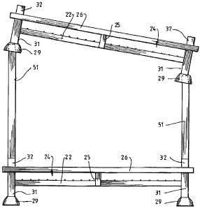
Referring to the drawings there is shown in Figure I an improved stackable
stillage
system for transport and display of articles including a plurality of
stillages 11, 12, 13,
14. However the substantial benefit of the system is in its use of a plurality
of releasable
height adjustment elements 51.
The stillages 11, 12, 13, 14 shown in Figure 1A for transport and display of
articles
include a base frame 21 of generally rectangular configuration having a planar
central
6
CA 02661913 2009-02-26
platform 23 comprising a wire mesh type structure. The base frame also
includes a
peripheral side edge 22 on which the platform is mounted.
As shown in this embodiment, the base frame 21 of the bottom stillage 14 is
supported
off the ground, by support legs 31 located at each corner of the rectangular
base frame.
The base frame 21 is further strengthened by cross-members 26 connecting
between
support legs 31 and forming uppermost portion of the side frame 24. Therefore
the side
frame 24 of the stillage includes substantially vertical members 25 extending
between
peripheral side edge 22 and uppermost cross-members 26.
The support legs 31 include a central portion having an upper end forming a
connecting
head 32 and a lower end where there is formed a bulbous foot 29, which has an
internal
recess (not shown). As shown in Figure 1A, the foot 29 contacts the ground and
stabilises the stillage system during transport and display of articles.
Further the spacing
and strength of the base frame allows ready transporting by forklift or the
like.
As shown in detail in Figure 1B the stillage includes a connecting head 32
mounted on
the base frame or the support legs and extending above the side frame 24 and
able to
engage and be enveloped by the corresponding foot 29 of second stillage in a
stackable
array as shown in detail in Figure IA. The internal recess of the foot 29 (not
shown) is
shaped to stably receive the upper end of the support leg forming the
connecting head 32
of a neighbouring stillage to form a stable stack of stillages.
Referring to Figures 2A, 2B and 2C, there is shown a closer view of upper end
of the
support leg 31 forming the connecting head 32 and having an L-shaped cross-
section.
Spaced along its length are two spaced apart substantially L-shaped sleeve
members 35,
36 forming sleeve for receiving a height adjustable element 51111 sliding
relation with
the support leg. Thereby each of the connecting heads 32 is shaped to receive
a
corresponding height adjustment element which in turn is adapted to engage the
foot of
a second stillage in a stackable array, wherein the distance and angle between
one
platform of one stillage and a platform of an adjacent stillage in a stack of
stillages can
be adjusted to provide accommodation for a range of different sized articles
in the stack
7
CA 02661913 2009-02-26
and to angle at least one of the stillages for display of articles in the
stillages following
transport of said stillages.
The height adjustment element 51 is shown in detail in Figures 3A, 3B and 4A.
In this
embodiment the height adjustment element consists of a lower portion 52 of
corresponding cross section to the openings of the sleeve member 35, 36. The
height
adjustment element 51 includes a tongue 53 appended to the lower portion 52
and
protruding and extending towards along the height adjustment element 51 to its
lowest
end. In use the tongue slides into engagement around outside of the upper
sleeve
member 36 and therefore must be suitably spaced from the lowest end of the
height
adjustment element 51 to allow engagement of the lower end 52 of the height
adjustment element 51 through both sleeve members 35, 36. The tongue provides
dual
function of precisely limiting the depth of a height adjustment element and
maintaining
close engagement of the L-shaped lower section and the L-shaped connecting
head of
the support leg for structural strength. Thereby height adjustment element 51
is stably
housed within the spaced apart sleeve members 35, 36 in an abutting relation
with the
support leg.
As shown in Figures 4B and 4C the adjustment elements 51 may be selectively
chosen
with particular length to space a stillage above a second stillage to allow
holding of
articles of height requiring such spacing. However for transport the height
adjustment
elements 51 can be removed for more compact transport after use.
However as shown in Figures 5A and 5B a further substantial advantage is
achieved by
substituting separate height adjustment elements of differing length.
The height adjustment element has a shaped cross section which is received by
a second
stillage in a stacicable array, wherein the distance and angle between one
platform and its
neighbouring platform in a stack of stillages can be adjusted to provide
accommodation
for a range of different sized articles in the stack and display said
articles.
Referring to Figures 4C, 5A and 5B, there is illustrated an array of stillages
mounted on
8
CA 02661913 2009-02-26
top of each other or one stillage is able to be disposed at an angle to
another. The
advantage of this arrangement is that space between adjacent stillages in an
array can be
adjusted to hold a range of different sized articles during transport. A
further advantage
is that once the articles have reached their destination, the array of
stillages can be
further adjusted to angle one platform relative to another. In this way
articles, which
have been transported can then be displayed professionally by reconfiguring
the array of
stillages after reaching a destination.
It can be seen particularly in Figures 5A and 513 that the shape of the foot
of each
support leg includes a bulbous structure with a recessed under portion. This
is an
important feature that allows stable stacking of one stillage on top of
another but
particularly allows angular stacking relative to each other. It is the
recessed under
portion having an outwardly expanding cavity to the open bottom for receiving
an upper
portion of the height adjustment element of an adjacent stillage in an array
that tends it
to a central position and thereby a stable configuration regardless of the
different
heights. Clearly practical limitations apply due to tipping of the articles in
the stillage.
However within such practical limitations this configuration of engagement
provides a
stable system.
It should be understood that the above description is of a preferred
embodiment and
included as illustration only. It is not limiting of the invention. Clearly
variations of the
improved stackable stillage system would be understood by a person skilled in
the art
without any inventiveness and such variations are included within the scope of
this
invention as defined in the following claims.
9