Note: Descriptions are shown in the official language in which they were submitted.
CA 02661921 2009-02-26
WO 2008/025785 PCT/EP2007/058967
Capsule for brewing a beverage
The present invention relates to a capsule for preparing and delivering a
beverage in a brewing device. The present invention more particularly aims at
providing a capsule adapted to deliver brewed tea although other beverages can
be
successfully brewed in the capsule.
Quality of a tea beverage is highly dependent on the quality of the leaf tea
ingredients, i.e., the tea origin used (soil, drying, blending, etc.) and
their storage
conditions. For instance, tea ingredients are usually sensitive to oxygen and
light.
Preferred tea ingredients are taken from loose leaves, chiselled or broken
into small
fragments. However, brewing conditions are also important to take full
advantage of
the quality of the ingredients used.
Different beverage capsules for brewing beverages in a suitable beverage
machine are known. However, according to the prior art, an external piercing
member, which is part of the beverage machine, is usually used to create an
outlet
from the cartridge. This operation amounts to undesirable physical interaction
between the beverage and the machine parts. In particular, cross-contamination
may
occur when two different cartridges are sequentially brewed without cleaning
the
machine. Taste cross-contamination happens when a taste residue is left by a
first
capsule on permanent parts of the machine that can consequently affect the
taste of
a second capsule which is brewed just after the first capsule. For tea, this
can be an
issue with certain tea varieties that deliver a high aroma profile such as
mint tea or
other highly flavoured varieties. Also tea residue may constitute a soil for
bacterial
growth and may lead to hygiene issues which need to be tackled.
Therefore, the present invention aims at proposing a design for a capsule that
enables to maintain freshness of the ingredients, promotes optimal conditions
for the
preparation of a tea beverage and the like, and reduces the cross-
contamination
problems.
In the present application, the terms "capsule" or "cartridge" or "package"
are
considered as synonymous. The term "capsule" will be preferentially used. The
words
"brewing" or "infusion" are used as synonymous. The term "brewing fluid"
generally
refers to the liquid that serves to infuse the beverage ingredients, more
generally, hot
water.
In the present application, the term "tea" encompasses all type of leaf tea
such as
green tea, black tea, white tea, chai tea, flavoured tea and herbal or fruit
tea. The
term "leaf tea" or "leaf ingredient" refers to brewable tea or other
ingredients in
CA 02661921 2009-02-26
WO 2008/025785 PCT/EP2007/058967
-2-
whatever form such as complete, cut or chiselled leaves, small fragments of
leaves,
powder or dust.
According to a first aspect of the present invention, a capsule is provided
that is
adapted to brew or infuse beverages in a beverage machine that may provide the
following advantages:
- the capsule is less complicated and less expensive to produce,
- the beverage delivery is cleaner and it reduces or eliminates the taste
cross-
contamination and hygiene issues,
- the convenience of the capsule handling, i.e., insertion and collection of
the
used capsules can be improved.
For these purposes as well as many possible others, the invention relates to
a capsule for the preparation of a beverage in a beverage machine
comprising :
a brewing enclosure containing one or more beverage ingredients;
filtering means delimiting at least one filtering side of the brewing
enclosure,
beverage flow guiding means configured to guide the beverage to a beverage
outlet of the capsule,
a shell and a protective cover that is attached to the shell and forms with
the
shell a gas tight container for the beverage ingredients;
wherein
the capsule comprises an opening element arranged outside the brewing
enclosure and configured to open the gas-tight container in order to create
the
beverage outlet, said gas tight container integrally housing the beverage flow
guiding
means and the opening element.
Therefore, according to one aspect of the invention, the opening element and
the flow guiding means are a part of the capsule itself. This feature
practically
eliminates all physical interaction between the beverage and the machine
parts. An
advantage of this arrangement is that it avoids cross-contamination and
results in
less cleaning.
The capsule can comprise an overflow wall positioned in the in the path of the
brewed liquid after the filtering means, the overflow wall comprising at least
one
overflow aperture. The overflow wall and the cover can further face each
other, and
at least a portion of the side of the overflow wall facing the cover can be
configured
to support the cover.
An advantage of this arrangement is that it promotes a more "direct flow"
approach with less chance of the brewed liquid to contaminate parts of the
brewing
device while ensuring, at the same time, that the liquid fills the brewing
enclosure
CA 02661921 2009-02-26
WO 2008/025785 PCT/EP2007/058967
-3-
completely during brewing so that the ingredients are properly infused and
product
concentration in the cup is properly controlled.
The opening element can further be arranged flush with the portion of the side
of the overflow wall that supports the cover, until the gas tight container is
opened.
The beverage flow guiding means can comprise a beverage flow channel
arranged on the side of the overflow wall that faces the cover and for
connecting at
least one overflow aperture with the beverage outlet. A groove can further be
formed
in the side of the overflow wall facing the cover. This groove can be
configured to
house the opening element, and a downstream portion, at least, of the beverage
flow
channel joining with said groove. The side of the overflow wall facing the
enclosure
can further feature a raised portion, which corresponds to a recessed portion
of the
side of the overflow wall facing the cover. This recessed portion can form at
least part
of the groove.
An upstream portion of the beverage channel can further be separate from
said groove, and it can be configured so as to avoid contact between the
beverage
and one end of the opening element.
The filtering means can comprise a plurality of studs protruding from the side
of the overflow wall facing the enclosure. Alternatively, the filtering means
can
comprise a paper filter arranged between the overflow wall and the enclosure.
The
paper filter and the studs can possibly be combined.
The opening element can be a perforating element for perforating an outlet in
a wall of the gas-tight container or an element adapted to create an outlet by
breaking a joint between two parts of the container. The perforating element
can
further have a generally elongated shape with two opposing ends. The
perforating
element can be configured to be pushed from a starting position to an "in use"
position when mechanical pressure is applied onto a first opposing end, the
second
opposing end being configured to pierce, go through or de-seal the protective
cover
when the perforating element is pushed into the "in use" position. The first
opposing
end can further be configured to be pushed by an external mechanical pusher. A
portion of the cover, between the mechanical pusher and the first opposing
end, can
be configured to be pierced by the mechanical pusher.
A shoulder can further be formed in the first opposing end of the perforating
element, so that when the mechanical pusher is activated, it can apply
pressure onto
the shoulder. The perforating element can further be configured to function
like a
ram, pressure applied onto the first opposing end causing the perforating
element to
slide longitudinally into the "in use" position. The second opposing end of
the
perforating element can further carry a piercing point that faces a perforable
zone of
CA 02661921 2009-02-26
WO 2008/025785 PCT/EP2007/058967
-4-
the cover when the perforating element is in the starting position. In the "in
use"
position of the perforating element, the piercing point can further extend
below the
lowermost part of the capsule.
A second aspect of the present invention relates to a beverage machine
comprising a device designed for brewing a beverage on the basis of
ingredients
contained in a capsule,
this beverage brewing device comprising:
- means for retaining the capsule in a defined position,
- first opening means for opening a hot water inlet into the capsule while
the capsule is retained in the defined position,
- second opening means for opening a beverage outlet from the capsule
while the capsule is retained in the defined position,
wherein the retaining means and the first and second opening means are
controlled by a common actuator.
According to this second aspect, the second opening means can further
comprise a mechanical pusher arranged above the defined position of the
capsule
and designed to slide downwards when actuated, so as to manoeuvre an opening
element integrally housed inside the capsule.
The beverage machine can further be designed in such a way that, in the
defined position, the beverage outlet of the capsule protrudes from an
underside of
the brewing device so that brewed liquid does not encounter any permanent part
when flowing down from the beverage outlet.
An advantage of this arrangement is that the brewed liquid can be delivered
vertically and smoothly from the capsule into the cup; this minimizes the
formation of
turbulence or foam and generally provides for a clean and elegant delivery.
An embodiment of the present invention will now be described, by way of
example only, with reference to the accompanying drawings, in which:
figure 1 is a schematic illustration of both a capsule according to one
particular embodiment of the present invention and a brewing device for the
capsule,
shown before brewing;
figure 2 is a schematic illustration of the capsule and the brewing device of
figure 1, shown during brewing of the capsule;
figure 3 is a plane view showing the overflow wall of the capsule of figure 1,
viewed from the cover side, so as to show the perforating element in
"starting"
position;
figure 4 is a plane view similar to figure 3 showing the perforating element
in
"in-use" position;
CA 02661921 2009-02-26
WO 2008/025785 PCT/EP2007/058967
-5-
figure 5 is a plane view showing the overflow wall of the capsule of figure 1,
viewed from the filtering side;
figures 6A to 6E depict the operation of a particular embodiment of a
beverage brewing device adapted for using the capsule of the present
invention.
First of all, the general brewing principle of the invention will be explained
in
relation to figures 1 and 2.
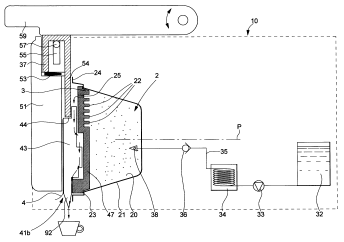
A capsule system is provided that comprises a capsule 2 and a beverage
brewing device 10. For simplicity, the beverage brewing device is only
schematically
depicted and may, in reality, comprise additional technical features within
the normal
knowledge of the person skilled in the art. The capsule comprises an enclosure
20
containing beverage ingredients such as leaf tea and the like. The enclosure
is
formed by a cup-shaped housing 21 that is closed by an overflow wall or plate
3. The
content of the enclosure is preferably protected from gas and light. The
housing may
have different cross-sections such as a circular, ellipsoid, square,
rectangular or
polygonal, and this cross-section determines the general outline of the flat
overflow
wall 3. As can be seen in figures 3 to 5, the cross-section of the capsule is
preferably
chosen so as to indicate naturally to a user the proper direction for
insertion of the
capsule 2 into the brewing device 10. Therefore, the outline of the cover 2,
as well as
that of the overflow wall 3 preferably does not show rotational symmetry. The
outline
of the cover can, for instance, be egg-shaped or shield-shaped with broad
topside
and a more pointed bottom side.
The enclosure is sized to accommodate a dose of leaf beverage ingredient of
typically about between 1 to 10 grams, preferably 2 to 5 grams. The dose of
leaf
ingredient may depend on the final volume of beverage to produce. For an
individual
cup of tea, a typical dose can be of about 2 grams whereas for a tea pot, a
typical
dose can be of about 8 to 10 grams. As clearly apparent in figure 1, the
capsule is
positioned relative to the brewing device so that the overflow wall 3 extends
substantially vertical and from substantially the bottom of the enclosure. For
this, the
capsule is preferably positioned in a "vertical" orientation in the brewing
device 10.
The cup-shaped housing 21 can be so oriented with its large opening and its
bottom
oriented in a vertical position.
The overflow wall 3 further comprises at least one (preferably several)
overflow apertures 25. The overflow apertures are placed at least above the
3/4 of the
height of the enclosure. The overflow wall is maintained in place by a
peripheral inner
shoulder 23 of the housing 21. The side of the overflow wall or plate 3 facing
the
enclosure carries filtering means. According to the present particular
embodiment, the
filtering means consist of an arrangement of roughly parallel studs 22
protruding from
CA 02661921 2009-02-26
WO 2008/025785 PCT/EP2007/058967
-6-
the side of the overflow wall. As is shown in figure 5, the studs are
relatively closely
spaced and form a regular lattice. More specifically, the studs 22 should be
arranged
closely enough to enable the lattice to function as a filter and keep the
majority of the
solid particles contained in the brewed beverage from leaving the enclosure.
The
adequate distance between neighbouring studs will depend on the size of the
food
fragments that are brewed. Typically, this distance is in the range between
0.5 and 5
mm. The studs 22 are preferably made integral with the overflow wall 3. The
overflow
wall and the studs can be made from plastic by injection moulding or by any
other
appropriate technique known to the person skilled in the art. Figure 5 shows
that the
arrangement of studs comprises both broad studs 22a and narrow studs 22b. The
diameter of the broad studs lies in between about 0.5 and 3 mm. and diameter
of the
narrow studs lies in between about 0.5 and 2 mm. Every broad stud has a narrow
stud for closest neighbour and vice versa. In figure 5, the pattern formed by
a pair of
neighbouring studs, one broad and one narrow, repeats itself regularly, and
one can
further observe that the studs form rows across the surface of the overflow
wall 3.
The capsule is closed by a cover 4 that hermetically seals the cup-shaped
housing 21. This cover is attached to the peripheral outer rim 24 of the
housing. The
cover can be attached to the peripheral rim by gluing or welding, or any other
appropriate technique known to a person skilled in the art. Both the cover and
the
housing can be made of oxygen barrier materials so as to form an oxygen tight
container. In this way, the enclosure 20 can be substantially free of oxygen
so that
the freshness of the beverage ingredients can be preserved during an extended
period of time. The enclosure may contain flushed inert gas such as N2, N20 or
C02. The cover 4 can be a flexible membrane or a semi-rigid plastic part.
Suitable
materials include, but are not limited to, plastics, PET, aluminium foil,
polymeric film,
paper, and the like.
As shown in figures 3 and 4, in the present example, two lateral channels 40a
and 40b run along the side of the wall 3 that faces the cover 4. The channels
extend
from the overflow apertures 25 to a location where the lateral channels join
near the
lowermost part of the overflow and support wall 3. The side of the overflow
wall 3
facing the cover further comprises a vertical groove 91 housing a perforating
element
43 that extends along the groove and can be manoeuvred from outside the
capsule.
As depicted, the peripheral channels 40a and 40b are in a symmetrical
arrangement
in relation to groove 91. Figures 3 and 4 further show that the channels 40a
et 40b
are separated from the central groove 91 by two prominent zones referenced 46a
and 46b. This arrangement allows the brewed liquid to be kept from the rear
end of
the perforating element 43. Prominent zones 46a and 46b extend at least as far
out
CA 02661921 2009-02-26
WO 2008/025785 PCT/EP2007/058967
-7-
from the overflow wall as the perforating element 43. Preferably, the faces of
zones
46a and 46b are flush with the perforating element 43. The two prominent zones
form
walls on either side of the groove 91 and serve as lateral guiding means for
the
mobile perforating element 43. Zones 46a and 46b further play the role of
supporting
pillars for the protective cover 4.
The channels 40a and 40b are intended to guide beverage from the overflow
apertures 25 to a tearable or pierceable zone 41a of the cover. The zone 41a
is
located near the lowermost part of the cover 4 and it also faces the lower end
of the
groove 91. The zone 41a is intended to be torn or pierced by the perforating
element
43 in order to create a beverage outlet from the capsule. Alternatively, the
tearable or
pierceable zone can be replaced by a detachable zone of the cover that can be
separated from the outer rim 24 of the housing 21.
In the present embodiment, the groove 91, which houses the perforating
element, is considerably deeper than the channels 40a and 40b. As can be
understood from figures 1 and 2, the deepest section of the groove 91 is
arranged in
a recessed portion of the overflow wall 3. In the present example, if the side
of the
overflow wall facing the brewing enclosure was completely planar, the
thickness of
the overflow would not be sufficient to accommodate the groove 91. Therefore,
in
order to provide space for the groove 91, the part of the overflow wall 3
opposite the
deepest section of the groove 91 features a raised or prominent portion 47. In
the
present embodiment, the raised portion 47 (also shown in figure 5) extends
approximately as far as the tips of the studs 22 forming the filtering means.
The
particular arrangement which has just been described has the advantage of
being
more compact than would an arrangement where the side of the overflow wall
facing
the enclosure was entirely planar.
The perforating element 43 can have the general shape of an elongated
beam. In the present embodiment, the perforating element extends along
practically
the full length of the groove 91. A shoulder 44 is formed near the rear of the
perforating element 43. When pressure is applied from the top onto the
shoulder 44,
the perforating element can slide downward along the groove 91. The downward
pressure is preferably applied by an external mechanical pusher 37, which is
part of
the beverage machine. The front end of the perforating element 43 carries a
piercing
point 92, which is arranged so as to come into contact with the cover and to
puncture
it when the perforating element 43 is pushed down the groove 91. In this way,
a
beverage outlet 41 b is created in the cover 4.
The shape of the shell of the capsule is not very critical. For different
reasons,
preference is given to a truncated cone, or to ellipsoidal or hemispherical
shapes.
CA 02661921 2009-02-26
WO 2008/025785 PCT/EP2007/058967
-8-
The shell can be manufactured industrially at lower cost by plastic
thermoforming or
aluminium deep drawing. This shape with smoother corners also favours the
removal
of the handling means, so as to allow the ejection of the capsule.
Turning to the brewing device 10, it comprises capsule handling means
comprising a fixed front plate 51 and a movable part (not shown). The movable
part is
arranged to press the cover side of the capsule 2 against the front plate, in
order to
immobilize the capsule and hold it in the "vertical" orientation, as defined
(figures 1
and 2). The movable part can comprise machine jaws or any suitable mechanical
enclosing means that can open and close about the capsule and can maintain it
firmly in place. There is no need for providing high closing force since the
fluid
pressure in the capsule remains relatively low and, preferably, as close as
possible to
the atmospheric pressure. Besides, the capsule itself can withstand the low
brewing
pressure. Therefore, the capsule does not necessarily need to be entirely
enclosed
but simply held water-tightly in place during brewing. This contributes to a
simplification of the machine and reduces machine costs.
The brewing device comprises a water supply 32, such as a water tank, a
water pump 33, a heater 34 and a hot water injection line 35 that is
associated with
the movable part of the handling means. The brewing device may also comprise a
controller and a user interface board (not shown) to manage the beverage
preparation cycles as known in the art. A backpressure valve 36 can be
provided to
lower the pressure at the entry side of an injection member 38. This injection
member
is designed to go through shell 2 of the capsule in order to serve as a water
inlet. The
injection member 38 can be a needle(s) or blade(s) or any other appropriate
device.
Of course, the backpressure valve could be omitted and a low pressure pump
could
be used that delivers fluid at low pressure. A medium to high pressure pump
may
however be preferred because of its robustness and reliability and so be used
in
combination with a backpressure valve.
The brewing device further comprises a mechanical pusher 37 that, in
association with the perforating element 43, forms perforation means, which
are
provided for creating an outlet near the lowermost part of the cover 4. The
mechanical pusher 37 is arranged so as to be able to slide up and down in an
opening formed in the uppermost part of the fixed front plate 51 of the
brewing
device. The mechanical pusher comprises a rod 54 that extends downwards from
the
body of the pusher. The body of the pusher 37 is supported by a spring 53
arranged
between the lower side of the body and a shoulder of the front plate. The body
of the
mechanical pusher further comprises a vertical slot 55 arranged to receive a
horizontal stop 57. When the mechanical pusher is in its rest position (figure
1), the
CA 02661921 2009-02-26
WO 2008/025785 PCT/EP2007/058967
-9-
spring 53 pushes the bottom end of the slot 55 against the stop 57. When the
pusher
is in its active position (figure 2), the top end of the slot abuts against
the stop.
In the present example, the perforation means further comprise a lever arm
59. This lever arm is arranged to come into contact with the top side of the
mechanical pusher 37, whenever the lever is lowered. As depicted in figure 2,
by
lowering the lever arm 59 completely, a user of the capsule system 1 drives
the
mechanical pusher into its active position. It should be understood that, in
an
alternative embodiment, the mechanical pusher could be driven into its active
position
automatically, by means of a solenoid or any other equivalent driving means.
The mechanical pusher is used to manoeuvre the perforating element 43.
When the mechanical pusher 37 moves from it's rest position to its active
position,
the mechanical pusher 37 cuts through the upper part of the cover 4 and comes
directly into contact with the shoulder 44 formed near the rear-end of the
perforating
element 43. In an alternative embodiment, instead of piercing the cover, the
mechanical pusher 37 could press against a deformable zone of the upper part
of the
cover 4, in order to force this zone against the shoulder 44. As previously
described,
mechanical pressure, applied directly or indirectly, by the pusher 37, onto
the
shoulder 44, causes the perforating element to slide along the groove 91 so as
to
bring about the opening of a beverage outlet 41b near the lowermost part of
the
cover 4.
In an alternative embodiment, it would be possible to dispense with the
shoulder 44 and have the mechanical pusher 37 simply press against the rear
end of
the perforating element 43. However, as shown in figure 2, one advantage of
having
the shoulder 44 is that when the rod 54 of the mechanical pusher 37 comes into
contact with the shoulder 44, the rear end of the perforating element is held
down
against the overflow wall 3 by the side of the rod. This advantageous feature
ensures
that the perforating element is properly guided during its travel down groove
91.
Once the mechanical pusher 37 has caused the piercing element 43 to
complete its downward travel, the pusher 37 can either retract out of the
capsule or
stay in its active position. However, the perforating element 43 preferably
remains in
the "in use" position depicted in figures 2 and 4. In this position, the
piercing point 92
extends out of the beverage outlet 41b. The piercing point 92 preferably
extends
below the lowermost part of the capsule. In this way, the piercing point 92
can
function as beverage guide, along which the fluid coming out of the beverage
outlet
can run down until it falls straight into a cup. In this configuration,
surface tension
naturally causes the beverage to run along the length of the surface of the
piercing
CA 02661921 2009-02-26
WO 2008/025785 PCT/EP2007/058967
-10-
point 92, thus avoiding turbulence and foam, and providing for a clean and
elegant
flow from the capsule directly into the cup.
The mechanical pusher 37 can be activated either during or after (preferably
during) the closing of the capsule handling means about the capsule. However,
it
should be understood that according to the invention, the mechanical pusher
could
also be dispensed with. In this case, the perforating element 43 would be
manoeuvred manually preferably before fitting the capsule 2 into the beverage
brewing device 10.
Figures 6A to 6E depict the operation of a particular embodiment of a
beverage brewing device adapted for using the above described capsule. A
particular
implementation of the method of the invention will now be described in
relation to
figures 6A to 6E as well as figure 2. A user first inserts a capsule manually
into an
opening in the top of the brewing device. In so doing, the user holds the
capsule in
the above mentioned "vertical" orientation. The capsule then drops through the
vertical opening, until it reaches a pre-fixation position in which it is held
by pre-
fixation means (not shown). For example, the pre-fixation means can be a pair
of
flexible arms. These arms hold the capsule in the position schematically
depicted in
figure 6A. In this position, the capsule is held at a small distance from, and
facing, the
front plate 51. At this stage, the movable part 61 of the capsule handling
means is
sitting clear of the front plate 51 in what corresponds to the movable part's
"open"
position. As shown in figure 6A, at this stage, the movable part is slightly
rotated
relative to the horizontal plane, as will be explained in further details
later on.
The movable part 61 comprises a hollow opening 63 whose shape is
designed to match the contour of the shell 21 of the capsule. The movable part
is
connected to a manually operable lever arm 59. When a user operates the lever
arm,
the movable part 61 first moves into the position depicted in figure 6B. In
this
intermediate position, the movable part and the front plate 51 have
practically
engaged each other. Furthermore, the shell 21 of the capsule 2 is now held in
the
hollow opening 63 of the movable part. The flexible arms that held the capsule
during
the first stage are now useless, and they are pushed aside by the advancing
movable
part 61, in such a way that the flexible arms disengage from the capsule.
Before brewing begins, both a water inlet and a beverage outlet are opened in
the capsule. As previously explained, a hot water injection line 35 (shown in
figures 1
and 2) and an injection member 38 are associated with the movable part 61. The
lever arm 59 is designed to control both the closing of the movable part and
the
displacements of the injection member 38. When the user lowers the lever arm
completely, the movable part presses the capsule against the front plate 51. A
the
CA 02661921 2009-02-26
WO 2008/025785 PCT/EP2007/058967
-11-
same time, the fluid injection member 38 moves from its previous retracted
position to
a protruding position as depicted in figure 6C. The forward movement of the
fluid
injection member 38 causes it to go through the capsule's shell 21. Capsules
made of
plastic material are difficult to pierce. However, the sides of the hollow
opening 63
give additional support to the shell of the capsule, making it less likely
that the plastic
wall will deflect when engaged by the injection member. When the lever arm
nears its
lowermost position (figure 6C), the injection line 35 begins supplying hot
water. The
hot water flows into the capsule through the injection member 38. The hot
water is
injected at relatively low pressure, preferably, at a pressure not exceeding 1
bar,
even preferably 0.2 bar, above atmospheric pressure. Hot water slowly fills
the
enclosure and submerges the beverage ingredients contained in it. The beverage
is
filtered by passing through the filtering means 22 at different vertical
levels up to the
upper level of the fluid in the enclosure.
As previously explained, lowering the lever arm 59 completely, additionally
activates the mechanical pusher 37. Therefore, as water begins to flow into
the
enclosure, the pusher 37 causes the perforating element 43 to slide downwards
under the cover 4, so as to bring about the opening of a beverage outlet 41 b
near the
lowermost part of the cover of the capsule. In this way, the brewed liquid can
be
evacuated from the enclosure 20 through the overflow apertures 25 and along
the
beverage guiding means, so as to finally leave the capsule through the
beverage
outlet 41b. One will understand that according to this particular embodiment,
the
mechanical pusher 37 is activated during and near the end of the closing
movement
of the capsule handling means.
The beverage coming out of the overflow apertures 25 is then guided down
the two lateral channels 40a and 40b (figure 4) until it reaches the lower
part of the
perforating element 43. The beverage then continues downwards running along
the
surface of the perforating element in the vertical groove 91 (figure 4). As
the point 92
of the perforating element extends below the lowermost part of the capsule,
the
beverage is guided along the surface of the piercing point 92 to its tip, and
then falls
straight into a cup (as shown in figure 2).
When a user of the beverage device wants to remove the used capsule, he
raises the lever arm 59. Raising the lever arm releases the mechanical pusher
37,
which is brought back into its rest position by the spring 53 (figure 6D).
However, the
transition from the brewing stage (figure 6C) to the capsule insertion state
(figure 6E)
is not simply a reversal of the closing movement. Indeed, when the movable
part
separates from the front plate 51, the injection member 38 does not retract,
but
remains in its protruding position. This is due to friction existing between
the injection
CA 02661921 2009-02-26
WO 2008/025785 PCT/EP2007/058967
-12-
member 38 and the surrounding sides of the hole in the shell 21. The injection
member can thus retain the capsule inside the hollow opening 63 of the movable
part. The movable part 61 therefore takes the capsule 2 with it as it
separates from
the front plate 51.
As a user gradually turns the lever arm 59 upwards, the movable part 61 is
progressively rotated relative to the horizontal plane. Furthermore, during
the final
transition from the stage depicted in figure 6D to the stage depicted in
figure 6E, the
injection member 38 finally retracts from its protruding position. The capsule
2, which
was hitherto held by the frictional engagement with the injection member,
comes lose
of the tilted movable part. The capsule thus falls into a waist container (not
shown)
arranged bellow the beverage brewing device.
It should be noted that, according to an alternate embodiment, the injection
member 38 can be rigidly fixed to the movable part 61, in such a way that the
injection member is permanently maintained in its protruding position.
According to
this alternate embodiment, when the lever arm is raised, the tilting movement
of the
movable part 61 (figure 6E) causes the capsule to come loose of both the
injection
member 38 and the hollow opening 63.
It will be understood that various modifications and/or adaptations can be
made to the embodiments described in the present description without departing
from
the scope of the invention defined by the annexed claims. In particular the
filtering
means do not need to comprise studs. The filtering means can be of any kind
that a
person skilled in the art would consider appropriate. In particular, the
filtering means
could be in the form of a traditional paper filter. The filtering means could
also
comprise both a paper filter and an arrangement of studs.
It should also be noted that the overflow aperture(s) can advantageously be
placed above the 4/5 of the total height of the enclosure; thus ensuring a
more
complete submergence of the beverage ingredients and a slower evacuation of
the
beverage from the enclosure which favours a better infusion process.
The "total height" of the enclosure is meant to be the total distance
separating
the lowermost point of the enclosure to the uppermost point of the enclosure
when
the capsule is positioned in the beverage machine ready for the brewing
operation. In
a possible mode, the extension of the filtering means can be substantially
equal to
the total height of the enclosure.
It can be noted that a "direct flow" can be obtained where the brewed liquid
is
dispensed directly into the recipient 6 (e.g., cup, mug and the like). By
"direct flow", it
is meant that the outlet 41b is arranged in respect to the brewing device so
that the
brewed liquid does not encounter any permanent device or part when leaving the
CA 02661921 2009-02-26
WO 2008/025785 PCT/EP2007/058967
-13-
outlet. In other words, the outlet is placed sufficiently low and laterally
spaced from
the capsule handling means to avoid any significant contact of the liquid with
these
members when released.