Note: Descriptions are shown in the official language in which they were submitted.
CA 02662069 2011-07-22
-1-
Capsule for the preparation of a beverage
The present invention relates to a capsule for preparing and delivering a
beverage in a brewing device. The present invention more particularly aims at
providing a capsule adapted to deliver brewed leaf tea although other
beverages can
be successfully brewed in the capsule.
Leaf tea ingredients are generally obtained from loose leaves that are
chiselled
or broken into small fragments. Brewing of these fragments can lead to the
presence
of large quantities of insoluble particles mixed with the infused solution.
Therefore,
when a capsule is designed specifically for delivering tea, it is important
that it
comprise filtering means. These filtering means should be adapted to let the
liquid
beverage freely out of the capsule, while simultaneously keeping all but a
negligible
amount of the undesirable ingredient particles inside the brewing enclosure.
European Patent application No. 05109566.9 describes several embodiments
of a capsule adapted for brewing tea in a beverage machine. The capsule
comprises
a filtering wall delimiting one filtering side of the brewing enclosure. An
overflow wall
comprising at least one overflow aperture is positioned in the path of the
brewed
liquid after the filtering. In one particular embodiment, the filtering wall
extends
substantially from the bottom to the top of the enclosure. This arrangement
provides
a large filtering surface and thus favours a lower brewing pressure. Another
feature
of this particular embodiment is that the overflow wall is parallel to the
filtering wall,
and that an interstitial space separates the two walls. This configuration
allows for the
liquid that has gone through the filter to move upwards in the interstitial
space until it
reaches the overflow aperture. This aperture is sufficiently close to the top
of the
brewing enclosure. In this way, the beverage ingredients can be entirely
submerged
by the low pressure brewing fluid, while the flow rate from the capsule
remains within
the acceptable range.
The capsule described in European patent application No. 05109566.9 is based
on a brewing principle that promotes the delivery of high quality tea.
However, as
previously described, the capsule comprises both a filtering wall and an
overflow wall
with an interstitial space between the two. It may further comprise a cover
that faces
the overflow wall. These features lead to a relatively complex structure that
can be
expensive to produce. Therefore, it would be desirable to provide a capsule
based on
the same or similar brewing principle but with a simplified, easier to
manufacture and
cheaper structure.
In the present application, the terms "capsule" or "cartridge" or "package"
are
considered as synonymous. The term "capsule" will preferentially be used. The
words
CA 02662069 2009-02-26
WO 2008/025715 PCT/EP2007/058756
-2-
"brewing" or "infusion" are used as synonymous. The term "brewing fluid"
generally
refers to the liquid that serves to infuse the beverage ingredients, more
generally, hot
water.
In the present application, the term "tea" encompasses all type of leaf tea
such
as green tea, black tea, white tea, chai tea, flavoured tea and herbal or
fruit tea. The
term "leaf tea" or "leaf ingredient" refers to brewable tea or other
ingredients in
whatever form such as complete, cut or chiselled leaves forming fragments of
leaves.
The present invention provides a capsule that is adapted to brew or infuse
beverages in a beverage machine that may provide the following advantages:
- the capsule is less complicated and less expensive to produce,
- the quality of the beverage can be improved, in particular, in relation to
the
beverage concentration into the cup, the taste and the reduced turbidity,
- the beverage delivery is cleaner and it reduces or eliminates the taste
cross-
contamination and hygiene issues,
- the convenience of the capsule handling, i.e., insertion and collection of
the
used capsules can be improved.
For these purposes as well as many others possible, the invention relates to a
capsule for brewing food fragments in a beverage machine comprising:
an enclosure containing fragments;
filtering means delimiting at least one filtering side of the enclosure,
wherein
an overflow wall is positioned in the path of the brewed liquid after the
filtering
means and comprises at least one overflow aperture; wherein said filtering
means is
integral with the overflow wall.
Furthermore, the filtering means are preferably configured to provide
filtration
both for beverage flowing in the direction of the overflow wall and for
beverage
flowing along the overflow wall and towards the overflow aperture.
Having the filtering means that are integral with the overflow wall allows to
produce them in one single piece such as in a injected plastic, for instance,
that can
obtained by a process of injection moulding. This feature of the invention can
therefore drastically reduce the cost of making the capsule.
Furthermore, the filtering means preferably extends from below a median
horizontal plane passing through the enclosure when the capsule is oriented so
that
at least one overflow aperture is placed above said plane.
Therefore, according to one aspect of the invention, but without willing to be
bound to any theoretical model, the filtering means are designed to behave a
little like
a "siphon" to enable the denser liquid to flow upwards along the overflow wall
in order
CA 02662069 2009-02-26
WO 2008/025715 PCT/EP2007/058756
-3-
to pass through the overflow aperture and to become dispensed, while at the
same
time, the beverage ingredients can be submerged by the brewing fluid therefore
avoiding bypassing areas in the enclosure and ensuring that the mass of
ingredients
fully interacts with the brewing fluid.
As a result, the capsule of the invention proposes a design that combines
both the advantages of the gravimetric top-down directional brewing where the
denser liquid can be captured and the advantages of the upward directional
brewing
where the full mass of product can be fully and slowly submerged but does not
retain
the disadvantages of each of said brewing principles.
In one mode, the filtering means comprise a plurality of studs protruding from
the side of the overflow wall facing the enclosure. The studs can be arranged
in rows
on the wall so as to form a regular pattern. The distance between neighbouring
studs
is less than the average size of the food fragments brewed in the capsule.
This
arrangement insures that the studs will form an obstacle for most of the
insoluble tea
fragments contained in the brewed liquid flowing into, or through, the
arrangement of
studs. The studs thus can provide filtration both for beverage flowing in the
direction
of the overflow wall and for beverage flowing along the overflow wall towards
the
overflow aperture.
The arrangement of studs can extend substantially from the bottom of the
enclosure to the top of the enclosure, while leaving substantially no large
gap
between the studs that might allow solid food ingredient to enter. These
arrays thus
create a sufficiently large filtering surface for the brewed liquid, which
favours a lower
brewing pressure in the enclosure and a slow flow, while the flow rate can
stay within
the acceptable range. The surface of the overflow wall on which the studs are
distributed can be at least 500 mm2, preferably of from 600 to 1500 mm2.
Trials at
about 700 mm2 provided good results with a delivered tea beverage having low
turbidity.
The studs can form a regular lattice featuring a plurality of rows extending
along two perpendicular directions, e.g., horizontally and vertically. The
distribution of
the studs can be such that the studs are spaced further apart along one
direction
than along another. This feature can be used to promote the flow of beverage
towards the overflow aperture. In another possible embodiment, the studs are
spaced
apart the same distance in both perpendicular directions.
In one aspect, the at least one overflow aperture is situated above the 3/4 of
the height of the enclosure; even preferably, the aperture is substantially
horizontally
aligned with the top end of the enclosure. As a result the whole mass of the
beverage
CA 02662069 2009-02-26
WO 2008/025715 PCT/EP2007/058756
-4-
ingredients can be properly submerged and consequently properly brewed
regardless
of the filling level of the enclosure by the beverage ingredients.
In another aspect, the studs can have substantially the same length.
According to the invention, the studs are integral with the overflow wall. The
overflow wall and the studs can be made from a variety of materials including,
but not
limited to PET or PP.
According to the invention, the capsule is closed in a gas-tight manner. The
capsule can further comprise perforation means comprising at least one
perforating
element configured to perforate a wall of the gas-tight container in order to
create the
beverage outlet from the said perforated wall of the capsule.
The capsule may further comprise flow guiding means configured to guide the
beverage from the at least one overflow aperture to the beverage outlet of the
capsule.
The beverage flow guiding means and the perforating element are integrally
enclosed within the gas-tight capsule until it is used. The flow guiding means
and
perforating element can be protected by a perforable protective cover. One
advantage of having the perforating element and the flow guiding means as a
part of
the capsule itself is that they are physically separated from the external
environment.
This feature prevents pollution of the flow guiding means during storage
before use.
Another advantage of having the perforating element and the flow guiding means
as
a part of the capsule is that practically no physical interaction is produced
between
the beverage and the machine parts, which avoids cross-contamination issues
and
results in less cleaning.
The perforating element is preferably configured to create the beverage outlet
in the protective cover. The beverage flow guiding means, which have the
function of
conducting the brewed liquid smoothly to the beverage outlet from the capsule,
can
also be positioned adjacent to the protective cover.
Furthermore, the beverage outlet is preferably placed at a region of the cover
that is substantially opposite to the overflow aperture(s), thus promoting a
more
"direct flow" approach with less chance of the brewed liquid to contaminate
parts of
the brewing device while ensuring, at the same time, that the liquid overflow
is
properly carried out in the capsule during brewing so that the ingredients are
properly
infused and product concentration in the cup is properly controlled.
The capsule can be conceived with a certain asymmetry in order to facilitate a
proper insertion in the brewing device by the user. For this, the capsule can
have an
elongated shape with an axial distance and a shorter transversal distance and
the at
least one puncture means or puncture indicating means can be aligned along the
CA 02662069 2009-02-26
WO 2008/025715 PCT/EP2007/058756
-5-
axial distance. As a result, the user is forced to insert the capsule in a
predetermined
orientation that is desirable for a correct operation of the capsule as
aforementioned.
In a mode, the capsule can be ovoid.
As used herein, "food fragments" refer broadly to food, nutritional and/or
medicinal solid material which is intended to be brewed or extracted with a
brewing
liquid but is not entirely dissolvable, extractable or dispersible in the
brewing liquid so
that solid material is left in the capsule after brewing. The fragments have a
size
which usually exceeds the size of powder. The fragments may typically have
individual a size of between about 0.5 mm and 20 mm. The fragments may be cut,
crushed or chiselled. The fragments may be fragments taken from plant leaves,
flowers, stalks, roots, seeds or grains. Also fragments may also be entire
leaves. The
fragments may be formed from tea or other plants.
Embodiments of the present invention will now be described, by way of
example only, with reference to the accompanying drawings, in which:
Figure 1 is a schematic illustration of a capsule brewing system before
brewing according to a particular embodiment of the invention;
Figure 2 is a schematic illustration of a the capsule brewing system of figure
1
during brewing of the capsule of the invention;
Figure 3 is a plane view of overflow wall of the capsule of figure 1 showing
the
filtering means on the side of the overflow wall facing the enclosure.
First of all, the general brewing principle of the invention will be explained
in
relation to figures 1 and 2 and a first possible embodiment of the capsule of
the
invention.
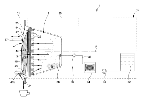
A capsule system 1 is provided that comprises a capsule 2 and a beverage
brewing device 10. For simplicity, the beverage brewing device is only
schematically
depicted and may, in reality, comprise additional technical features within
the normal
knowledge of the person skilled in the art. The capsule comprises an enclosure
20
containing beverage ingredients such as leaf tea and the like. The enclosure
is
formed by a cup-shaped housing 21 that is closed by an overflow wall or plate
3. The
content of the enclosure is preferably protected from gas and light. The
housing may
encompass different cross sections such as a circular, ellipsoid, square,
rectangular
or polygonal section that determine as a matter of fact the general
circumference of
the flat overflow wall 3. The enclosure is sized to accommodate a dose of leaf
beverage ingredient of typically about between 1 to 10 grams, preferably 2 to
5
grams. The dose of leaf ingredient may depend on the final volume of beverage
to
produce. For an individual cup of tea, a typical dose can be of about 2 grams
whereas for a tea pot, a typical dose can be of about 8 to 10 grams. As
clearly
CA 02662069 2009-02-26
WO 2008/025715 PCT/EP2007/058756
-6-
apparent in figure 1, the capsule is positioned relative to the brewing device
so that
the overflow wall 3 extends substantially vertical and from substantially the
bottom of
the enclosure. For this, the capsule is preferably positioned in a "vertical"
arrangement in the brewing device 10. The cup-shaped housing 21 can be so
oriented with its large opening and its bottom oriented in a vertical
position.
The overflow wall or plate 3 carries filtering means. These filtering means
consist of an arrangement of roughly parallel studs 22 protruding from the
side of the
overflow wall facing the inside of the enclosure 20. As can be seen in the
figures, the
studs are relatively closely spaced and form a regular lattice. More
specifically, the
studs 22 should be arranged closely enough to enable the lattice to function
as a
filter and keep the majority of the solid particles contained in the brewed
beverage
from leaving the enclosure. The adequate distance between neighbouring studs
will
depend on the size of the food fragments that are brewed. Typically, this
distance is
in the range between 0.5 and 5 mm. The studs 22 are preferably made integral
with
the overflow wall 3. The overflow wall and the studs can be made from plastic
by
injection moulding or by any other appropriate technique known to the person
skilled
in the art.
As can further be seen in the figures, the studs 22 can be of a relatively
short
length. This length is usually in between 0.5 and 8 mm. As is apparent in the
cross-
sectional view of figures 1 and 2, the distal ends of a plurality of studs 22
are located
approximately in a plane that lies parallel and a short distance away from the
overflow wall 3. In the following description, the expression "filtering
space" will be
used to refer to the space lying between the plane defined by the tips (or
distal ends)
of the studs and the overflow wall. This narrow filtering space is referenced
"s" on the
figures. The overflow wall 3 further comprises at least one overflow aperture
25. The
overflow aperture is placed at least above the 3/4 of the height of the
enclosure. The
overflow wall is maintained in place by a peripheral inner shoulder 23 of the
housing
21.
The capsule is closed by a cover 4 that hermetically seals the cup-shaped
housing 21. This cover is attached to the peripheral outer rim 24 of the
housing. The
cover can be attached to the peripheral rim by gluing or welding, or any other
appropriate technique known to a person skilled in the art. Both the cover and
the
housing can be made of oxygen barrier materials so as to form an oxygen tight
container. In this way, the enclosure 20 can be substantially free of oxygen
so that
the freshness of the beverage ingredients can be preserved during an extended
period of time. The cover 4 can be a flexible membrane or a semi-rigid plastic
part.
CA 02662069 2009-02-26
WO 2008/025715 PCT/EP2007/058756
-7-
Suitable materials include, but are not limited to, plastics, PET, aluminium
foil,
polymeric film, paper, and the like.
The enclosure is preferably oxygen free and may contain flushed inert gas
such as N2, N20 or 002.
In the present example, the outer side of the overflow wall 3 that faces the
cover 4 forms an internal channel 40 that leads from the overflow aperture 25
to a
tearable or pierceable zone 41 a of the cover, which is intended to be easily
torn or
pierced by appropriate perforation means in order to create a beverage outlet.
Alternatively, the tearable or pierceable zone can be replaced by a detachable
zone
of the cover that can be separated from the outer rim 24 of the housing.
A perforating element 43, forming part of the above mentioned perforation
means, is housed in the space between the cover 4 and the overflow wall 3. The
perforating element 43 can be manoeuvred from outside the capsule, and it can
have
the general form of a beam with two opposing ends 44, 45. A first one of these
ends
44 tapers out to form a flattened zone, while the other end 45 has a pointed
shape.
The perforating element 43 extends along a longitudinal (vertical) space;
i.e., an
internal channel 40 and is designed to swing around a pivot 46 supported by
the
sides of the channel 40. The pointed end 45 of the beam faces the tearable,
pierceable or detachable zone 41a of the cover 4. In order to activate the
perforating
element 43, pressure is applied onto the flattened end 44 from outside the
capsule,
across the flexible cover 4. The applied pressure causes the perforating
element 43
to swing like a lever. Accordingly, while the flattened end 44 of the beam is
pushed in
the direction of the overflow wall 3, the pointed end 45 moves away from the
overflow
wall 3, thus pressing the tearable, pierceable or detachable zone of the cover
outwards, with sufficient force to puncture it. In this way, a beverage outlet
41b is
created in the cover 4. The pressure that is applied onto the flattened end 44
of the
perforating element 43, in order to create the beverage outlet 41b, can be
applied
manually by the user prior to inserting the cartridge into the brewing device.
However,
as will be explained hereafter, the pressure is preferably applied by
appropriate
mechanical means.
The shape of the shell of the capsule is not very critical. For different
reasons,
preference is given to a truncated cone, or to ellipsoidal or hemispherical
shapes.
The shell can be manufactured industrially at lower cost by plastic
thermoforming or
aluminium deep drawing. This shape with smoother corners also favours the
removal
of the handling members and so ejection of the capsule.
As more particularly shown in figure 3, the capsule can also be shaped in
general to promote and indicate to the user a particular direction for
insertion into the
CA 02662069 2009-02-26
WO 2008/025715 PCT/EP2007/058756
-8-
brewing device. For instance, the capsule, more particularly the cover, can
have an
asymmetrical egg-shaped or shield-shaped profile with broad topside and more
pointed bottom side.
Turning to the brewing device 10, it comprises capsule handling members 30,
31 that are configured to hold the capsule in the "vertical" arrangement as
defined.
These handling members 30, 31 can be machine jaws or any suitable mechanical
enclosing means that can open and close about the capsule and can maintain it
firmly in place. There is no need for providing high closing forces since the
involved
fluid pressure in the capsule remains relatively low and, preferably, as close
as
possible to the atmospheric pressure. Also, since the capsule can withstand
the low
brewing pressure therefore the capsule does not necessarily need to be
entirely
enclosed but simply held water tightly in place during brewing to prevent
water
leakage. This participates to a simplification of the machine and reduces
machine
costs.
The brewing device comprises a water supply 32, such as a water tank, a
water pump 33, a heater 34 and a hot water injection line 35 that is managed
through
the handling member 30. The brewing device may also comprise a controller and
a
user interface board (not shown) to manage the beverage preparation cycles as
known in the art. A backpressure valve 36 can be provided to lower the
pressure at
the entry side or injection member 38 (such as a needle(s) or blade(s) and a
water
inlet) in the capsule. Of course, the backpressure valve could be omitted and
a low
pressure pump could be used that delivers fluid at low pressure. Medium to
high
pressure pump may however be preferred because of their robustness and
reliability
and so used in combination with a backpressure valve.
The brewing device may further comprise a mechanical pusher 37 configured
to cooperate with the perforating element 43 in order to create an outlet in
the
tearable, pierceable or detachable zone 41 a of the cover 4. As shown in
figure 1, the
mechanical pusher 37 can be activated after closing of the handling members
30, 31
about the capsule. The mechanical pusher is used to manoeuvre the perforating
element 43. In order to do so, the mechanical pusher 37 is forced or guided
toward
the flattened end 44 of the perforating element 43. Moving forwards, the
mechanical
pusher 37 forces a deformable zone 47 of the flexible cover 4 against the
flattened
end 44, thus applying pressure onto the flattened surface through the cover 4.
The
pressure, thus applied on the perforating element, brings about the opening of
a
beverage outlet 41b, as previously described. To avoid any cross-contamination
problems, pusher 37 will preferably be arranged so as not to perforate the
cover 4 in
the deformable zone 47.
CA 02662069 2009-02-26
WO 2008/025715 PCT/EP2007/058756
-9-
In the present example, the mechanical pusher 37 can be driven by a solenoid
or any other equivalent drive means or even manually. However, it should be
understood that according to the invention, the mechanical pusher could also
be
dispensed with. In this case, the perforating element 43 would be manoeuvred
manually preferably before fitting the capsule 2 into the beverage brewing
device 10.
In relation to figure 2, the method of the invention works as follows. A
capsule
is inserted in the brewing device and the capsule handling members are closed
about
the capsule to position it with the sealing wall being substantially
vertically oriented. A
beverage outlet 41 b is created in the cover 4 by the mechanical pusher 37
activating
the perforating element 43. On the opposite side of the capsule, the fluid
injection
member is introduced in the capsule's enclosure. Hot water is thus injected in
the
capsule at relatively low pressure, preferably, at a pressure not exceeding
0.2 bar.
Hot water slowly fills the capsule and submerges the beverage ingredients in
the
enclosure. A portion of the beverage flows into the filtering space "s".
However, most
of the insoluble tea fragments contained in the beverage are held back by the
studs
22. As depicted in the figures, the studs are truncated at their distal ends.
An
advantage of this last feature is that studs with flat ends form a more
efficient barrier
for the insoluble particles.
When enough hot water has flown into the capsule, the level of the brewed
beverage reaches the height of the overflow aperture, allowing filtered
beverage to
start to flow out of the filtering space through the overflow aperture. A
denser portion
5 of the beverage may tend to settle in the bottom of the enclosure. This
portion can
also enter the filtering space since this space extends from the bottom of the
enclosure. The denser beverage can then reach the overflow aperture by flowing
upwards in the filtering space "s" driven by a pressure gradient. The rest of
the
beverage is also filtered on entering the filtering space "s" at different
vertical levels
up to the upper level of the fluid in the enclosure. As is visible on the
figure, the studs
have rounded profiles. This shape has the advantage of offering less
resistance to
the passage of a fluid than would angular profiles. This promotes the upward
flow of
the beverage inside the filtering space. Although the rounded profile of the
studs
favours the upwards flow of the beverage, it does not prevent the studs from
acting
like a filter for the beverage flowing upwards as well as for the beverage
flowing into
the filtering space. In this way, the beverage going through the overflow
aperture is
filtered twice; once on entering the filtering space, and a second time while
flowing
upwards inside the filtering space.
Turning now to figure 3, we can see that the arrangement of studs comprises
both broad studs 22a and narrow studs 22b. The diameter of the broad studs
lies in
CA 02662069 2009-02-26
WO 2008/025715 PCT/EP2007/058756
-10-
between about 0.5 and 3 mm and diameter of the narrow studs lies in between
about
0.5 and 2 mm. Every broad stud has a narrow stud for closest neighbour and
vice
versa. In figure 3, the pattern formed by a pair of neighbouring studs, one
broad and
one narrow, repeats itself regularly. One can further observe that the studs
form rows
across the surface of the overflow wall 3. Furthermore, studs stand closest
together
in rows that are oriented in the vertical direction (the spacing can be
between about
0.5 and 2 mm) and conversely studs are spaced the furthest apart in the
horizontal
direction (the spacing can be between 0.2 and less than 2 mm). This
arrangement
favours the upward flow of the brewed beverage.
It should be noted that the overflow aperture is placed above the 3/4 of the
total
height of the enclosure and is preferably placed above the 4/5 of the total
height of
the enclosure; thus ensuring a more complete submergence of the beverage
ingredients and a slower evacuation of the beverage from the enclosure which
favours a better infusion process.
It can be noted that a "direct flow" can be obtained where the brewed liquid
is
dispensed directly into the recipient 6 (e.g., cup, mug and the like). By
"direct flow", it
is meant that the outlet is arranged in respect to the brewing device so that
the
brewed liquid does not encounter any permanent device or part when leaving the
outlet. In other words, the outlet is placed sufficiently low and laterally
spaced from
the capsule handling members of the beverage machine to avoid any significant
contact of the liquid with these members when released.