Language selection

Search

Patent 2662294 Summary

Third-party information liability

Some of the information on this Web page has been provided by external sources. The Government of Canada is not responsible for the accuracy, reliability or currency of the information supplied by external sources. Users wishing to rely upon this information should consult directly with the source of the information. Content provided by external sources is not subject to official languages, privacy and accessibility requirements.

Claims and Abstract availability

Any discrepancies in the text and image of the Claims and Abstract are due to differing posting times. Text of the Claims and Abstract are posted:

  • At the time the application is open to public inspection;
  • At the time of issue of the patent (grant).
(12) Patent: (11) CA 2662294
(54) English Title: MODULAR DESIGN FOR OPHTHALMIC SURGICAL PROBE
(54) French Title: CONCEPTION MODULAIRE DESTINEE A UNE SONDE CHIRURGICALE OPHTALMIQUE
Status: Granted
Bibliographic Data
(51) International Patent Classification (IPC):
  • A61F 9/007 (2006.01)
  • A61B 17/32 (2006.01)
(72) Inventors :
  • VALENCIA, SALOMON (United States of America)
  • LOPEZ, JOSE LUIS (United States of America)
  • AULD, JACK R. (United States of America)
(73) Owners :
  • ALCON INC. (United States of America)
(71) Applicants :
  • ALCON, INC. (Switzerland)
(74) Agent: KIRBY EADES GALE BAKER
(74) Associate agent:
(45) Issued: 2014-05-13
(86) PCT Filing Date: 2007-07-26
(87) Open to Public Inspection: 2008-05-08
Examination requested: 2012-06-13
Availability of licence: N/A
(25) Language of filing: English

Patent Cooperation Treaty (PCT): Yes
(86) PCT Filing Number: PCT/US2007/074433
(87) International Publication Number: WO2008/054900
(85) National Entry: 2009-02-27

(30) Application Priority Data:
Application No. Country/Territory Date
11/554,812 United States of America 2006-10-31

Abstracts

English Abstract

An ophthalmic surgical probe having a modular drive assembly and a skin that is removable from the drive assembly. This design simplifies probe manufacturing and provides greater manufacturing flexibility.


French Abstract

La présente invention concerne une sonde chirurgicale ophtalmique qui comprend un ensemble d'entraînement modulaire et une enveloppe pouvant se retirer de l'ensemble d'entraînement. Cette conception permet de simplifier la fabrication de la sonde et d'offrir une plus grande souplesse de fabrication.

Claims

Note: Claims are shown in the official language in which they were submitted.


What is claimed is:

1. An ophthalmic surgical probe provided in a modular construction,
comprising:
a single skin having a first opening and a second opening;
an engine having a body, said engine having a drive shaft support member and a

drive shaft extending axially from said engine ;
a needle holder;
a needle having a needle coupling rigidly coupled thereto ;
a cutter having a cutter coupling rigidly coupled thereto, said cutter being
slidably disposed within said needle; and
wherein:
said needle holder has a bushing disposed therein and an opening for
removably engaging said drive shaft support member;
said needle coupling operably and removably engages said bushing ;
said cutter coupling operably and removably engages said drive shaft;
and
said drive shaft support member, drive shaft, and cutter coupling are
operably disposed within said needle holder which is receivable through said
first opening such that said drive shaft support member, said needle holder,
and
said cutter coupling are disposed entirely within said skin and the needle
extends
through the second opening of the skin, the skin removably engaging and being
coupled to the body of the engine.
2. The ophthalmic surgical probe of claim 1 wherein said engine comprises
a pneumatic engine.
3. The ophthalmic surgical probe of claim 1 wherein said engine comprises
an electric engine.
4. The ophthalmic surgical probe of claim 1 wherein said probe is a
vitrectomy probe.

6

Description

Note: Descriptions are shown in the official language in which they were submitted.


CA 02662294 2009-02-27
WO 2008/054900
PCT/US2007/074433
MODULAR DESIGN FOR OPHTHALMIC SURGICAL PROBE
Field of the Invention
The present invention generally pertains to microsurgical instruments. More
particularly, but not by way of limitation, the present invention pertains to
microsurgical
instruments used in posterior segment ophthalmic surgery, such as vitrectomy
probes.
Description of the Related Art
Many microsurgical procedures require precision cutting and/or removal of
various body tissues. For example, certain ophthalmic surgical procedures
require the
cutting and/or removal of the vitreous humor, a transparent jelly-like
material that fills the
posterior segment of the eye. The vitreous humor, or vitreous, is composed of
numerous
microscopic fibers that are often attached to the retina. Therefore, cutting
and removal of
the vitreous must be done with great care to avoid traction on the retina, the
separation of
the retina from the choroid, a retinal tear, or, in the worst case, cutting
and removal of the
retina itself.
The use of microsurgical cutting probes in posterior segment ophthalmic
surgery
is well known. Such vitrectomy probes are typically inserted via an incision
in the sclera
near the pars plana. The surgeon may also insert other microsurgical
instruments such as
a fiber optic illuminator, an infusion cannula, or an aspiration probe during
the posterior
segment surgery. The surgeon performs the procedure while viewing the eye
under a
microscope.
Conventional vitrectomy probes typically include a hollow outer cutting
member,
a hollow inner cutting member arranged coaxially with and movably disposed
within the
1

CA 02662294 2013-09-30
hollow outer cutting member, and a port extending radially through the outer
cutting
member near the distal end thereof. Vitreous humor is aspirated into the open
port, and
the inner member is actuated, closing the port. Upon the closing of the port,
cutting
surfaces on both the inner and outer cutting members cooperate to cut the
vitreous, and
the cut vitreous is then aspirated away through the inner cutting member. U.S.
Patent
Nos. 4,577,629 (Martinez); 5,019,035 (Missirlian et al.); 4,909,249 (Akkas et
al.);
5,176,628 (Charles et al.); 5,047,008 (de Juan et al.); 4,696,298 (Higgins et
al.); and
5,733,297 (Wang) all disclose various types of vitrectomy probes.
Conventional vitrectomy probes include "guillotine style" probes and
rotational
probes. A guillotine style probe has an inner cutting member that reciprocates
along its
longitudinal axis. A rotational probe has an inner cutting member that rotates
about its
longitudinal axis. In both types of probes, the inner cutting members are
actuated using
various methods. For example, the inner cutting member can be moved from the
open
port position to the closed port position by pneumatic pressure against a
piston or
diaphragm assembly that overcomes a mechanical spring. Upon removal of the
pneumatic pressure, the spring returns the inner cutting member from the
closed port
position to the open port position. As another example, the inner cutting
member can
be moved from the open port position to the closed port position using a first
source of
pneumatic pressure, and then can be moved from the closed port position to the
open
port position using a second source of pneumatic pressure. As a further
example, the
inner cutting member can be electromechanically actuated between the open and
closed
port positions using a conventional rotating electric motor or a solenoid.
U.S. Patent
No. 4,577,629 provides an example of a guillotine style,
2

CA 02662294 2009-02-27
WO 2008/054900
PCT/US2007/074433
pneumatic diaphragm / mechanical spring actuated probes. U.S. Patent No.
5,176,628
shows a rotational dual pneumatic drive probe.
In many conventional vitrectromy probes, the engine and the shell or skin are
tied
together to yield a functional probe. A disadvantage to this is that the skin
serves as both
an ergonomic component as well as a part that is responsible for function.
Changing
between different probe types (i.e. 20, 23, 25 gage probes) requires that the
internal
features of the skin be changed to accommodate the corresponding functional
interfaces
such as seal design and tip geometry. This results in less flexibility.
Therefore, a need exists for an improved vitrectomy probe that exhibits more
flexibility. Such flexibility should enable future design and manufacturing
flexibility,
utilize a number of common components in overall probe design, and be able to
convert
to multiple gage size probes using the same engine parts.
Summary of the Invention
The present invention is an ophthalmic surgical probe having a skin removably
coupled to an engine, a needle holder, a needle, and a cutter. The engine has
a drive shaft
support member and a drive shaft extending axially from the engine. The needle
holder
has a bushing disposed therein and an opening for removably engaging the drive
shaft
support member. The needle has a first coupling rigidly coupled thereto. The
first
coupling is for removably engaging the bushing. The cutter has a second
coupling rigidly
coupled thereto. The cutter is slidably disposed within the needle, and the
second
coupling is for removably engaging the drive shaft.
3

CA 02662294 2009-02-27
WO 2008/054900
PCT/US2007/074433
Brief Description of the Drawings
For a more complete understanding of the present invention, and for further
objects and advantages thereof, reference is made to the following description
taken in
conjunction with the accompanying drawings, in which:
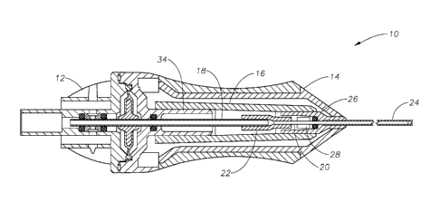
Figure 1 is a sectional view of the ophthalmic surgical probe of the present
invention; and
Figure 2 is an exploded, sectional view of the ophthalmic surgical probe of
Figure
1.
Detailed Description of the Preferred Embodiments
The preferred embodiments of the present invention and their advantages are
best
understood by referring to Figures 1-2 of the drawings, like numerals being
used for like
and corresponding parts of the various drawings.
Vitrectomy probe 10 consists of engine 12, shell or skin 14, needle holder 16,
drive shaft 18, cutter 20, and needle 24. Although the ophthalmic surgical
probe of the
present invention is described herein in connection with a vitrectomy probe
10, the
present invention is applicable to other ophthalmic or other surgical probes,
instruments,
and handpieces. Cutter coupling 22 is integrally formed on the proximal end of
cutter 20.
Needle coupling 26 is integrally formed on the proximal end of needle 24.
Drive shaft 18
extends axially from engine 12. Distal end of drive shaft 18 removably engages
cutter
coupling 22 of cutter 20. Drive shaft support member 34 removably engages
opening 36
of needle holder 16. Drive shaft support member 34, drive shaft 18, and cutter
coupling
22 are disposed within needle holder 16. Bushing 28 within needle holder 16
removably
engages needle coupling 26 of needle 24, such that cutter 20 is slidably
disposed within
needle 24. Needle coupling 26, needle holder 16, cutter coupling 22, drive
shaft 18, and
4

CA 02662294 2013-09-30
. -
drive shaft support member 34 are disposed entirely within skin 14. Skin 14
contains
opening 38 which removably engages body 40 of engine 12. Needle 24 extends
through opening 42 in skin 14.
Engine 12 may be any type of engine suitable for driving vitrectomy probe 10,
but is most preferably a pneumatic engine. Drive shaft 18 may be made of any
suitable
material, but is most preferably stainless steel. Needle 24 and cutter 20 may
be made of
any material suitable for posterior segment ophthalmic surgery, but are most
preferably
made from surgical stainless steel. Skin 14, needle coupling 26, and cutter
coupling 22
are most preferably made from a lightweight material such as aluminum or rigid
plastic.
During manufacturing assembly, the modular design of probe 10 allows a
worker to quickly and easily switch between building probes of various needle
gages,
such as a probe 10 with a 20 gage needle 24, a 23 gage needle 24, or a 25 gage
needle
24. More specifically, the ability to quickly attach and remove skin 14 from
body 40 of
engine 12, to quickly couple different gages of needle 24 with needle holder
16 and
cutter 20 via needle coupling 26 and bushing 28, and to quickly couple cutter
20 to
drive shaft 18 via cutter coupling 22 greatly increases manufacturing
flexibility and
simplifies the assembly process of probe 10.
It is believed that the operation and construction of the present invention
will be
apparent from the foregoing description. While the apparatus and methods shown
or
described above have been characterized as being preferred, various changes
and
modifications may be made therein.
5

Representative Drawing
A single figure which represents the drawing illustrating the invention.
Administrative Status

For a clearer understanding of the status of the application/patent presented on this page, the site Disclaimer , as well as the definitions for Patent , Administrative Status , Maintenance Fee  and Payment History  should be consulted.

Administrative Status

Title Date
Forecasted Issue Date 2014-05-13
(86) PCT Filing Date 2007-07-26
(87) PCT Publication Date 2008-05-08
(85) National Entry 2009-02-27
Examination Requested 2012-06-13
(45) Issued 2014-05-13

Abandonment History

There is no abandonment history.

Maintenance Fee

Last Payment of $624.00 was received on 2024-06-18


 Upcoming maintenance fee amounts

Description Date Amount
Next Payment if standard fee 2025-07-28 $624.00 if received in 2024
$651.46 if received in 2025
Next Payment if small entity fee 2025-07-28 $253.00 if received in 2024
$264.13 if received in 2025

Note : If the full payment has not been received on or before the date indicated, a further fee may be required which may be one of the following

  • the reinstatement fee;
  • the late payment fee; or
  • additional fee to reverse deemed expiry.

Patent fees are adjusted on the 1st of January every year. The amounts above are the current amounts if received by December 31 of the current year.
Please refer to the CIPO Patent Fees web page to see all current fee amounts.

Payment History

Fee Type Anniversary Year Due Date Amount Paid Paid Date
Application Fee $400.00 2009-02-27
Maintenance Fee - Application - New Act 2 2009-07-27 $100.00 2009-07-07
Maintenance Fee - Application - New Act 3 2010-07-26 $100.00 2010-07-07
Maintenance Fee - Application - New Act 4 2011-07-26 $100.00 2011-07-12
Request for Examination $800.00 2012-06-13
Maintenance Fee - Application - New Act 5 2012-07-26 $200.00 2012-07-05
Maintenance Fee - Application - New Act 6 2013-07-26 $200.00 2013-07-09
Final Fee $300.00 2014-02-27
Maintenance Fee - Patent - New Act 7 2014-07-28 $200.00 2014-07-09
Maintenance Fee - Patent - New Act 8 2015-07-27 $200.00 2015-07-01
Maintenance Fee - Patent - New Act 9 2016-07-26 $200.00 2016-07-06
Maintenance Fee - Patent - New Act 10 2017-07-26 $250.00 2017-06-28
Maintenance Fee - Patent - New Act 11 2018-07-26 $250.00 2018-07-04
Maintenance Fee - Patent - New Act 12 2019-07-26 $250.00 2019-07-03
Registration of a document - section 124 2019-12-18 $100.00 2019-12-18
Maintenance Fee - Patent - New Act 13 2020-07-27 $250.00 2020-07-01
Maintenance Fee - Patent - New Act 14 2021-07-26 $255.00 2021-06-30
Maintenance Fee - Patent - New Act 15 2022-07-26 $458.08 2022-06-22
Maintenance Fee - Patent - New Act 16 2023-07-26 $473.65 2023-06-21
Maintenance Fee - Patent - New Act 17 2024-07-26 $624.00 2024-06-18
Owners on Record

Note: Records showing the ownership history in alphabetical order.

Current Owners on Record
ALCON INC.
Past Owners on Record
ALCON, INC.
AULD, JACK R.
LOPEZ, JOSE LUIS
NOVARTIS AG
VALENCIA, SALOMON
Past Owners that do not appear in the "Owners on Record" listing will appear in other documentation within the application.
Documents

To view selected files, please enter reCAPTCHA code :


To view images, click a link in the Document Description column. To download the documents, select one or more checkboxes in the first column and then click the "Download Selected in PDF format (Zip Archive)" or the "Download Selected as Single PDF" button.

List of published and non-published patent-specific documents on the CPD .

If you have any difficulty accessing content, you can call the Client Service Centre at 1-866-997-1936 or send them an e-mail at CIPO Client Service Centre.


Document
Description 
Date
(yyyy-mm-dd) 
Number of pages   Size of Image (KB) 
Description 2009-02-27 5 189
Representative Drawing 2009-02-27 1 19
Drawings 2009-02-27 2 45
Abstract 2009-02-27 1 60
Claims 2009-02-27 1 24
Cover Page 2009-07-03 1 39
Description 2013-09-30 5 189
Claims 2013-09-30 1 35
Representative Drawing 2014-04-17 1 12
Cover Page 2014-04-17 1 38
PCT 2009-02-27 1 48
Assignment 2009-02-27 4 100
Prosecution-Amendment 2013-04-03 3 121
Prosecution-Amendment 2012-06-13 1 38
Prosecution-Amendment 2012-06-18 1 32
Prosecution-Amendment 2013-09-30 8 340
Correspondence 2014-02-27 1 37