Note: Descriptions are shown in the official language in which they were submitted.
CA 02662295 2009-03-02
P11111R,8119
= 7U /1111 7111Ik 'INN 15*(12
FAX 01932762388 444 PnrOmmirh
Printed: 21/07/2008 ,DESCPAMD!
0E20070033371
Case No. 10405(2) = 1 =
HYDROCARBON RECOVERY PROCESS
= The present invention relates to a method for recovering hydrocarbons
from a
=porous and permeable subterranean hydrocarbon-bearing formation by injecting
a low
salinity water into the formation.
It has long been known that only a portion of the oil can be recovered from an
oil-
bearing subterranean formation as a result of the natural energy of the
reservoir. So-called
=
secondary recovery techniques are used to force more oil out of the reservoir,
the simplest
method of which is by direct replacement with another medium, usually water or
gas.
Water-flooding is one of the most successful and extensively used secondary
recovery Methods. Water is injected, under pressure,. into reservoir rocks via
injection
wells, driving the oil through the rock towards production wells. The water
used in water-
.
. flooding is generally saline water from a natural source such as seawater
(hereinafter
"source water").
= 15 The factors that control crude oil/brine/rock interactions and
their effect on
= wettability and oil recovery involve complex and sometimes competing
mechanisms. It
has been reported that oil recovery can be dependent on injection brine
concentration. In
particular, it has been shown in laboratory core studies by Morrow and co-
workers that the
use of a lower salinity injection water during water-flooding can increase oil
recovery
compared to the use of higher salinity water. P.L. McGuire, J.R. Chatham, F.
K. Paskvan,
D.M. Sommer, F.H. Carini: "Low Salinity Oil Recovery: An Exciting New EOR
Opportunity for Alaska's North Slope" Society of Petroleum Engineers, Vol. 2,
No. 93903,
2005, pages 422-436 describes later work with lower salinity water-flooding.
= But lower salinity waters are often not available at a well site and
would have to be
made by reducing the total ion concentration of higher salinity water using
techniques such =
as reverse osmosis or forward osmosis.
= There is thus a problem of how to enhance recovery of oil from an oil-
bearing
formation using a method which is either cheaper for the same recovery or
which gives
better oil recovery for the Same cost.
It has now been found that by manipulating the total multivalent cation
concentration of a low salinity injection water and by injecting a minimum
pore volume of
the manipulated low salinity water into an oil-bearing formation that the
residual oil
-firk
N 29/05/2008
ed at the EPO on May 29, 2008.16:08:40, p AMENDED SHEET
CA 02662295 2009-03-02
.7U/11 wing TIM 15'03 FAX 01932762388 44i Ann munirb , =
Phon7/1119
Printed 21107/2008, DESCPAMD;
GB2007003337
Case No. 10405(2) . la
= saturation of the formation may be reduced in comparison to injecting the
original low
= salinity water or a higher salinity water. In particular, it has been
found that the key to
=
=
10
=
-
=
= =
=
=
=
=
=
jived at the EPO on May 29, 2008 1608:40. P. AMENDED SHEET
[29/05/2008'
CA 02662295 2012-08-30
30109-188
2
better oil recovery is use of an injection water of a special lower
multivalent cation content
where the total dissolved solids content (TDS) of the injection water is in
the range of
200 to 10,000 ppm. It has also been found that enhanced oil recovery using a
low salinity
water is dependent upon the nature of the formation.
Thus, the present invention provides a method for increasing the recovery of
crude oil from a reservoir comprising at least one porous and permeable
subterranean
formation wherein the formation comprises sandstone rock and at least one
mineral that has a
negative zeta potential under the reservoir conditions and wherein crude oil
and connate water
are present within the pores of the formation, the method comprising:
injecting into the
formation an aqueous displacement fluid that displaces crude oil from the
surface of the pores
of the formation wherein the aqueous displacement fluid has a total dissolved
solids content
(TDS) in the range of 200 to 10,000 ppm and the fraction of the total
multivalent cation
content of the aqueous displacement fluid to the total multivalent cation
content of the connate
water is less than 1.
In one aspect, the invention relates to a method for increasing the recovery
of
crude oil from a reservoir comprising at least one porous and permeable
subterranean
formation wherein the formation comprises sandstone rock and at least one
mineral that has a
negative zeta potential under the reservoir conditions and wherein crude oil
and connate water
are present within the pores of the formation, the method comprising: (A)
injecting into the
formation a slug of an aqueous displacement fluid that displaces crude oil
from the surface of
the pores of the formation wherein the pore volume (PV) of the slug of the
aqueous
displacement fluid is at least 0.3 and less than 1 and the aqueous
displacement fluid has a total
dissolved solids (TDS) content in the range of 200 to 10,000 ppm and the
fraction of the total
multivalent cation content of the aqueous displacement fluid to the total
multivalent cation
content of the connate water is less than 1; and (B) subsequently injecting
into the formation a
drive water of higher multivalent cation content and/or higher total dissolved
solids content
than the aqueous displacement fluid.
CA 02662295 2012-08-30
30109-188
2a
In a further aspect, the invention relates to a method for increasing the
recovery
of crude oil from a reservoir comprising at least one porous and permeable
subterranean
formation wherein the formation comprises sandstone rock and at least one
mineral that has a
negative zeta potential under the reservoir conditions and wherein crude oil
and connate water
are present within the pores of the formation, the method comprising:
injecting into the
formation an aqueous displacement fluid that displaces crude oil from the
surface of the pores
of the formation wherein the aqueous displacement fluid has a total dissolved
solids (TDS)
content in the range of 200 to 10,000 ppm and the fraction of the total
multivalent cation
content of the aqueous displacement fluid to the total multivalent cation
content of the connate
water is less than 1 wherein the aqueous displacement fluid is injected into
the formation
during secondary recovery.
In a preferred embodiment of the present invention there is provided a method
for increasing the recovery of crude oil from a reservoir comprising at least
one porous and
permeable subterranean formation wherein (a) the formation comprises sandstone
rock and at
least one mineral that has a negative zeta potential under the reservoir
conditions; (b) crude oil
and connate water are present within the pores of the formation and the crude
oil comprises
components having anionic functional groups (hereinafter "anionic components")
and/or
components having cationic functional groups (hereinafter "cationic
components"); and, (c)
multivalent cations are adsorbed onto the surface of the pores of the
formation from the
connate water and are in equilibrium with free multivalent cations that are
dissolved in the
connate water and at least a portion of the adsorbed multivalent cations are
associated with
anionic components of the crude oil (hereinafter "oil-associated multivalent
cations") and/or
negatively charged functional groups on the surface of the pores of the
formation are
associated with cationic components of the crude oil (hereinafter "adsorbed
cationic
components"), the method comprising: injecting into the formation an aqueous
displacement
fluid having a total dissolved solids (TDS) content in the range of 200 to
10,000 ppm and
having displacement cations dissolved therein wherein the concentration of
multivalent
cations in the aqueous displacement fluid is less than the concentration of
free multivalent
cations in the connate
CA 02662295 2009-03-02
WO 2008/029124 PCT/GB2007/003337
3
water so that the oil-associated multivalent cations and/or the adsorbed
cationic =
components are displaced from the surface of the pores of the formation and
are replaced
with displacement cations that are adsorbed from the aqueous displacement
fluid thereby
displacing crude oil from the surface of the pores of the formation.
Preferably, the aqueous displacement fluid is passed through the formation
from an
injection well to displace crude oil from the surface of the pores of the
formation and the
displaced crude oil is recovered from a production well spaced from said
injection well.
However, it is also envisaged that the present invention may be applied to a
"huff and
puff' process where a production well is put through a cycle of injecting the
aqueous
displacement fluid from the well into the formation, leaving the well to soak
and then
producing oil from the well.
The formation, through which the aqueous displacement fluid passes, comprises
sandstone rock with which the oil is associated, whether by inclusion in pores
or between
grains or otherwise. The formation may also comprise other ingredients such as
quartz. In
addition, the formation comprises one or more minerals having a negative zeta
potential
under the reservoir conditions. Accordingly, the formation has a negative
surface electrical
charge under the reservoir conditions. "Zeta potential" is a parameter well
known in the
art and may be measured by standard means known to the person skilled in the
art. Zeta
potential is measured by forming a slurry of the mineral in an aqueous medium,
passing an
electric current through the slurry via electrodes and determining the
direction and speed of
the movement of the slurry particles. Preferably, the zeta potential of the
mineral is from -
0.1 to -50 mV, such as -20 to -50 mV under the reservoir conditions. By
"reservoir
conditions" is meant the temperature and pressure of the formation and the pH
of the
connate water. Typically, the temperature of the formation is in the range of
25 to 300 C,
for example, 50 to 200 C, in particular 100 to 150 C. Typically, the pressure
of the
formation is in the range of 100 to 1000 bar. Generally, the connate water has
a pH in the
range 4 to 8, in particular, in the range 5 to 7.
Typically, the formation comprises at least 0.1% of at least one mineral that
has a negative
zeta potential under the reservoir conditions, preferably 1 to 50%, more
preferably, 1 to
30% and especially 2.5 to 20% (all contents in this specification are
expressed by weight
unless otherwise stated). The mineral may be, a clay, in particular, clays of
the smectite
type (such as montmorillonite), pyrophyllite type, kaolinite type, illite type
and glauconite
CA 02662295 2009-03-02
WO 2008/029124
PCT/GB2007/003337
4
type. Preferably, the clay is non-swelling under the conditions of recovery of
crude oil
from the formation. Other examples of minerals that have a negative zeta
potential under
reservoir conditions include transition metal compounds, such as oxides and
carbonates,
for example, iron oxide, siderite, and plagioclase feldspars. The amount of
such mineral(s)
in the formation may be determined by X-ray diffraction using ground-up
formation rock.
It has been found that increasing levels of incremental oil recovery
correlates with
increasing amounts of the mineral(s) in the formation.
Multivalent cations, preferably divalent and/or trivalent cations, are
adsorbed onto
the surface of the pores of the formation from the connate water. Without
wishing to be
10_ bound by any theory, it is believed that the multivalent cations are
chemically adsorbed
onto the surface of the pores of the formation. It is also believed that the
adsorbed
multivalent cations are in equilibrium with multivalent cations contained in
the connate
water.
Examples of crude oil components having anionic functional groups ("anionic
components") include hydrocarbons having carboxylate, hydroxyl, phosphonate,
sulfate or
sulfonate functional groups. In particular, the anionic components of the
crude oil may be
naphthenates.
By the anionic components of the crude oil being "associated" with the
adsorbed
multivalent cations is meant that the anionic components may be directly or
indirectly
coordinated to the adsorbed multivalent cations. The anionic components of the
crude oil
may be directly coordinated to the adsorbed multivalent cations via ionic
bonding (termed
"cation bridging") or dative bonding (termed "ligand bridging").
Alternatively, the anionic
components of the crude oil may be indirectly coordinated to the adsorbed
multivalent
cation via,hydrogen bonding through the intermediary of one or more bridging
water
molecules (termed "water bridging"). The direct and indirect coordination of
anionic
components of the crude oil to adsorbed multivalent cations is illustrated
below with
respect to a carboxylic acid and adsorbed divalent cations (Ca2+ and Mg2+):
CA 02662295 2009-03-02
WO 2008/029124 PCT/GB2007/003337
<
/ - o
H '11-1
' 0
z 0 -
Ci 2+0 9a2+
Ca mg2+
I ¨lir r ____
Cation bridging Ugand bridging Water bridging
Examples of crude oil components having cationic functional groups ("cationic
components") include quaternary ammonium salts of the formula RRIR2R3N4X"
where the
5 R, RI, R2, and R3 groups represent hydrocarbon groups and X" is an anion,
for example,
chloride or bromide. Generally, the cationic components of the crude oil are
directly
coordinated to anionic groups that are present on the surface of the pores of
the formation
via ionic bonding. For example, as illustrated below, there may be cation
exchange
between the hydrogen ions of hydroxyl groups that are present on the surface
of clay
minerals and quaternary ammonium ions of formula RRIR2R3N+.
R, R2 R3
I
R ¨ fer
0¨
Cation exchange
The displacement cations of the aqueous displacement fluid may be multivalent
cations or monovalent cations. However, monovalent cations are less efficient
at
displacing the adsorbed multivalent cations (and their associated anionic
components of
the crude oil) and/or the adsorbed cationic components of the crude oil from
the surface of
the pores of the formation. Accordingly, it is preferred that at least some
multivalent
displacement cations are present in the aqueous displacement fluid with the
proviso that
the total multivalent cation content of the aqueous displacement fluid is less
than the total
multivalent cation content of the connate water.
CA 02662295 2009-03-02
WO 2008/029124
PCT/GB2007/003337
6
The fraction of the total multivalent cation content in the aqueous
displacement
fluid to the total multivalent cation content in the connate water
(hereinafter "multivalent
cation fraction") i less than 1, for example, less than 0.9. Generally, the
lower the
multivalent cation fraction the greater the amount of oil that is recovered
from a particular
formation. Thus, the multivalent cation fraction is preferably less than 0.8,
more
preferably, less than 0.6, yet more preferably, less than 0.5, and especially
less than 0.4 or
less than 0.25. The multivalent cation fraction may be at least 0.001,
preferably, at least
0.01, most preferably, at least 0.05, in particular at least 0.1. Preferred
ranges for the
multivalent cation fraction are 0.01 to 0.9, 0.05 to 0.8, but especially 0.05
to 0.6 or 0.1 to
0.5. The fraction of the total divalent cation content of the said aqueous
displacement fluid
, to the total divalent cation content of said connate water (hereinafter
"divalent cation
fraction") is also less than 1. The preferred values and ranges for the
multivalent cation
fraction may be applied mutatis mutandis to the divalent cation fraction.
Suitably, the monovalent displacement cations may be selected from Group I
metal
cations, in particular, Nat. The multivalent displacement cations are
preferably divalent
cations or trivalent cations. Divalent cations that may be employed as
displacement
+
cations include Group II metal cations, in particular, Ca2 and Mg2+ but also
Ba2+ and Sr,
preferably Ca2+. Trivalent cations that may be employed as displacement
cations include
Cr2+,Cr3+, Al3+, y2+ or V3+. The most effective displacement cations, have a
relatively high
charge density over their hydrated radius (the radius of the cation and its
closely bound
water molecules). Accordingly, Ca2+ is more effective as a displacement cation
than Mg2+.
Mixtures of displacements cations may be employed in the displacement fluid.
The sodium content of the aqueous, displacement fluid is usually 20 to 4,000
ppm,
preferably, 150 to 2,500, ppm, for example, 200 to 1,000 ppm. The fraction of
the sodium
content to half the multivalent cation content in the aqueous displacement
fluid is usually
greater than 1, preferably, 1.05 to 50, most preferably 5 to 40, in
particular, 5 to 20 or 20 to
40, the higher values usually being associated withligher TDS levels of the
aqueous
displacement fluid.
The aqueous displacement fluid usually has a calcium content of at least 1,
preferably at least 5 ppm, for example, at least 10 ppm. Typically, the
calcium content is
in the range of 1 to 100 ppm, preferably 5 to 50 ppm. The magnesium content of
the
aqueous displacement fluid may be at least 1 ppm, preferably at least 5 ppm,
more
CA 02662295 2009-04-02
30109-188
7
preferably at least 10 ppm. Typically, the magnesium content is in the range
of 5 to 100,
= preferably 5 to 30 ppm. The barium content of the aqueous displacement
fluid may be in
the range of 0.1 to 20, such as 1 to 10 ppm. The weight ratio of calcium to
magnesium is
usually 10:1 to 1:10 especially 10:1 to 1:1 such as 10:1 to 4:1, or 5:1 to 1:6
such as 1:1 to
1:6. Thus, the calcium content may be higher than the magnesium content.
Preferably, the
trivalent cation content of the aqueous displacement fluid is at least 1,
preferably, at least
10, for example, at least 20. Preferably, the multivalent cation content of
the aqueous
displacement fluid is at least 10, for example, at least 20 ppm, with the
proviso that the
multivalent cation fraetion is less than 1. Typically, the total content of
multivalent cation
in the aqueous displacement fluid is 1 to 200 ppm, preferably 3.to 100,
especially 5 to 50
ppm with the proviso that the multivalent cation fraction is less than 1.
The TDS content of said aqueous displacement fluid is at least 200 ppm,
preferably
at least 500 ppm. The TDS content may be up to 10,000 ppm; preferably, up to
8,000 ppm,
more preferably, up to 7,000 ppm. In particular, the TDS may be in the range
of 500 to
10,000 ppm, preferably, 1,000 to 8,000 ppm, for example, 1,000 to 5,000 ppm.
Preferably, the fraction of the multivalent cation content of the aqueous =
displacement fluid to the total dissolved solids (MS) content of said aqueous
displacement
fluid is less than 1 x 10⁻², such as 0.01-0.9 x 10⁴ preferably 0.1-0.8 x10⁻².
These fractions
may be applied mutatis mutandis to the fraction of the divalent cation content
of the
aqueous displacement fluid to the total dissolved solids (TDS) content of said
aqueous
displacement fluid.
The invention may be applied for enhanced recovery of oil from a formation
where
the connate water has a wide range of TDS levels, such as at least 500 ppm,
usually 500 to
200,000 ppm such as 2,000 to 50,000 ppm, in particular 2,000 to 5,000 ppm or
10,000 to
50,000 ppm especially 20,000 to 45,000 ppm. The connate water is the water
associated
with the oil in the formation and is in equilibrium with it, especially in
relation to its
= multivalent cation content, in particular its divalent cation (e.g.
calcium) content. The
- calcium content of the connate water is usually at least 150 ppm, such
as 200 to 30,000
- ppm, 200 to 6,000 ppm and especially 200 to 1,000 ppm. The magnesium
content of the
connate water is usually at least 150 ppm, such as 200 to 30,000 ppm, 200 to
6,000 ppm,
and especially 200 to 1,000 ppm. The total divalent cation content of the
connate water is
usually at least 180 ppm, such as 250 to 15,000 ppm, preferably, 350 to 3,000
ppm
=
CA 02662295 2009-03-02
WO 2008/029124
PCT/GB2007/003337
8
especially 400 to 2,000 ppm or 1,000 to 2,000 ppm. The weight ratio of calcium
to
magnesium in the connate water is usually 10:1 to 1:10, especially 10:1 to 1:1
such as 10:1
to 4:1 or 5:1 to 1:6, such as 1:1 to 1:6. Generally, connate water contains
low levels of
trivalent cations, usually less than 5 ppm.
The aqueous displacement fluid may be passed continuously into the formation.
However, it is preferred that the aqueous displacement fluid is passed in one
or more
portions of controlled pore volume, PV, (hereinafter referred to as "slugs").
The term
"pore volume" is used herein to mean the swept volume between an injection
well and a
production well and may be readily determined by methods known to the person
skilled in
the art. Such methods include modelling studies. However, the pore volume may
also be
determined by passing a high salinity water having a tracer contained therein
through the
formation from the injection well to the production well. The swept volume is
the volume
swept by the displacement fluid averaged over all flow paths between the
injection well
and production well. This may be determined with reference to the first
temporal moment
of the tracer distribution in the produced high salinity water, as would be
well known to the
person skilled in the art.
It has been found that the volume of the slug of aqueous displacement fluid
may be
surprisingly small yet the slug is still capable of releasing substantially
all of the oil that
can be displaced from the surface of the pores of the formation under the
reservoir
conditions. Generally, the pore volume (PV) of the slug of aqueous
displacement fluid is
at least 0.2 PV, as a slug of lower pore volume tends to dissipate in the
formation and may
not result in appreciable incremental oil production. It has also been found
that where the
pore volume of the aqueous displacement fluid is at least 0.3, preferably, at
least 0.4, the
slug tends to maintain its integrity within the formation (does not disperse
within the
formation) and therefore continues to sweep displaced oil towards a production
well.
Thus, the incremental oil recovery for a particular formation approaches a
maximum value
with a slug of at least 0.3 PV, preferably at least 0.4 PV, with little
additional incremental
oil recovery with higher pore volume slugs. Although, it is possible to
continue to inject
the aqueous displacement fluid into a formation, typically, the pore volume of
the slug of
aqueous displacement fluid is minimised since there may be limited injection
capacity for
the aqueous displacement fluid owing to the need to dispose of produced water.
Thus, the
pore volume of the aqueous displacement fluid is preferably less than 1, more
preferably
CA 02662295 2009-03-02
WO 2008/029124 PCT/GB2007/003337
9
less than 0.9 PV, most preferably, less than 0:7 PV, in particular, less than
0.6 PV, for
example, less than 0.5 PV. Typically, the slug of aqueous displacement fluid
has a pore
volume in the range of 0.2 to 0.9, preferably 0.3 to 0.6, and especially 0.3
to 0.45.
After injection of a pore volume of aqueous displacement fluid that achieves
the
maximum incremental oil recovery (preferably, a slug of aqueous displacement
fluid
having a pore volume of less than 1), a drive (or post-flush) water of higher
multivalent
cation content and/or higher TDS, usually both, may be injected into the
formation. Where
the slug of aqueous displacement fluid has a pore volume of less than 1, the
post-flush
water will ensure that the slug of aqueous displacement fluid (and hence the
released oil) is
swept through the formation to the production well. In addition, the injection
of the post-
flush water may be required to maintain the pressure in the reservoir.
Typically, the post-
flush water has a greater PV than the slug of aqueous displacement fluid.
Preferably the
post-flush water does not have a higher pH than the injected aqueous
displacement fluid,
and has not had alkali added tb it such as sodium hydroxide, sodium carbonate,
sodium
silicate or sodium phosphate.
Many sources of water for the aqueous displacement fluid may potentially be
used
including fresh water, seawater, brackish water, aquifer water, connate water
or produced
water. Fresh water may be obtained from a river or lake and typically has a
TDS content
of less than 1500 ppm. Brackish water may be obtained from tidal or estuary
river sources
and typically, has a TDS content of from 5000 to 25,000 ppm. In addition,
brackish water
may be obtained from an aquifer which may be in a separate stratum from a
stratum
associated with the crude oil. However, not all aquifer water is brackish
water. Thus, the
TDS content for aquifer water may be in the range of 1000 to 300,000 ppm.
Where
connate water or production water (water that is separated from the oil that
is produced
from a production well) is used as the source of the water for the aqueous
displacement
fluid, the connate water or produced water may have a TDS content in the range
of 2000 to.
300,000 ppm TDS. The use of connate water or produced water as a source of the
water
for the aqueous displacement fluid is advantageous where there are
restrictions on disposal
of connate water or produced water. Seawater may also be considered for the
source of the
water for the aqueous displacement fluid, whether inland seas of 15,000 to
40,000 ppm
such as the Caspian Sea or oceanic seas, for example, of 30,000 to 45,000 ppm
TDS. If
desired mixtures of waters may be used as the source of the water for the
aqueous
CA 02662295 2009-03-02
WO 2008/029124 PCT/GB2007/003337
displacement fluid, for example, a low TDS aquifer water mixed with a higher
salinity
water such as produced water or seawater. Use of mixed waters is particularly
important
when a new production well is being started as, initially, there may be no or
insufficient
produced water to be used as the water source for the aqueous displacement
fluid.
5 Where the TDS content of the source water and its multivalent cation
content are
already at the desired values for the aqueous displacement fluid to achieve
incremental
recovery of oil from a formation with a particular connate water, the source
water may be
used as aqueous displacement fluid without treatment to reduce its multivalent
cation
content. Examples of water that may be used as the aqueous displacement fluid
without
10 treatment include fresh water and low salinity aquifer waters. If
desired, while the
multivalent cation level may not be changed, the multivalent anion content
e.g. content of
divalent anions such as sulphate or carbonate or trivalent anions such as
phosphate may be
reduced e.g. by precipitation with divalent cations such as calcium, or by
anion exchange
(for example, using an anion exchange resin) or by nanofiltration using an
anion selective
membrane. If necessary, multivalent cations (in particular, divalent cations
and trivalent
cations) may be added to the fresh water or aquifer water to achieve the
desired multivalent
cation content.
Where the TDS content of the source water is already at the desired value for
the
aqueous displacement fluid but the multivalent cation level is higher than
desired for
incremental recovery of oil from a formation with a particular connate water,
the source
water is treated to reduce its multivalent cation level. Examples of such
source waters
include certain low salinity produced waters and certain low salinity aquifer
waters. The
treatment may be by precipitation e.g. by addition of sodium hydroxide, sodium
carbonate,
sodium bicarbonate, sodium phosphate or sodium silicate and separation of a
precipitate
comprising the multivalent cation (for example, by filtration or
centrifugation) thereby
producing a treated water of lower multivalent cation level for use as the
aqueous
displacement fluid. The treatment of the source water may also be by
nanofiltration e.g.
with a multivalent cation selective membrane such as Dow Filmtec NF series (in
particular,
NF40, NF4OHF, NF50, NF70, NF90, and NF270 membranes), Hydranautics ESNA1
series, Desal-5 membrane (Desalination Systems, Escondido, California), SU 600
membrane (Toray, Japan), or NRT 7450 and NTR 7250 membranes (Nitto Electric,
Japan).
The selective removal of multivalent cations from water of low TDS content
(brackish
CA 02662295 2009-03-02
WO 2008/029124 PCT/GB2007/003337
11
water TDS content or less) using such membranes is discussed in US 5,858,420
and in
Separation and Purification Technology, 37 (2004), "Removal of sulfates and
other
inorganics from potable water by nanofiltration membranes of characterized
porosity", by
K Kosutic, I Novak, L Sipos and B Kunst. Alternatively, the source water may
be treated
by being passed through a bed of a cation exchange resin, for example, a
hydrogen or
sodium cation exchange resin. These treatment methods (other than cation
exchange with
a hydrogen cation exchange resin) have the benefit of not substantially
increasing the pH
of the aqueous displacement fluid compared to the untreated water. If required
the treated
water may also have its multivalent anion content reduced as described above.
Where the source water has a higher TDS than desired for the aqueous
displacement fluid and where the multivalent cation level is also higher than
desired for
incremental recovery of oil from a formation with a particular connate water,
the source
water is treated to lower both its TDS content and its multivalent cation
content to the
desired values. Typically, the source water is treated to lower both its TDS
and
multivalent cation content to the desired values, for example, using reverse
osmosis,
forward osmosis or combinations thereof. Source waters that are treated in
this manner
include, seawater, higher salinity brackish waters, high salinity produced
waters and high
salinity aquifer waters. The membrane that is employed in the reverse osmosis
or forward
osmosis, may exclude substantially all of the dissolved solids in the source
water from
passing into the treated water (permeate). Suitable membranes that exclude
substantially
all of the dissolved solids are well known to the person skilled in the art.
Accordingly, the
treated water may have a TDS of as low as 200 ppm, and a divalent cation
content as low
as 1 to 2 ppm. Typically, the treated water will not contain any, trivalent
cations. If
desired, multivalent cations (divalent cations and/or trivalent cations) may
be added to the -
treated water with the proviso that the total multivalent cation content of
the treated water
is less than the total multivalent cation content of the connate water. Also,
if desired, salts
of monovalent cations may be added to the treated water to increase its TDS
content with
the proviso that the TDS content does not exceed 10,000 ppm. Alternatively,
the source
water may be treated using a "loose" reverse osmosis membrane, as described in
International Patent Application number WO 2006/002192 thereby directly
forming an
aqueous displacement fluid of the desired TDS content and desired multivalent
cation
content.
CA 02662295 2009-03-02
- MIN 7111D1 TRH 15p4 FAX 01932762388 444 on. MIMI ch
r1n1nin19
tt;Pialifilia:1/07/0.5.68'= 1:cig
esomD: GB2007003337
t11.(11 = tw,,,1,1,1,,,:m..AL =
Case No. 10405(2) 12
The aqueous displacement fluid may also contain water soluble polymeric
viscosifiers, such as natural gums, polyacrylamides and polyacrylic acids. For
avoidance
of doubt, these viscosifiers are not considered to contribute to the total TD
S content of the
aqueous displacement fluid.
It is envisaged that a surfactant may also be added to the aqueous
displacement
fluid, in particular sulphonates such as alkene benzene aulphonates, whether
as such or in a
micellar solution with emulsified hydrocarbons.
Preferably there is no added alkali, such as sodium hydroxide, sodium
carbonate,
sodium bicarbonate, sodium silicate or sodium phosphate in the aqueous
displacement
fluid. Where any of such alkaline materials has been added to reduce the
multivalent
cation content of a high multivalent cation content source water, the pH of
the aqueous
displacement fluid should be less than 0.5 higher, preferably, less than 0.2
higher than that .
. of the source water.
= The aqueous displacement fluid contacts the formation rock, associated
with which
is oil, which may have a density of 0.9659-0.7389 girril, preferably 0.8762-
0.8017 giml,
such as 0.034-0.8762 g/m1 (an American Petroleum Institute (API) gravity of at
least 15-
60 preferably at least 30-45 , such as. 2030O).
- In the method of the invention, the aqueous displacement fluid is
preferably
injected under pressure, for example,. of 10,000 to 100,000 IcPa (100 to 1000
bar) into at
least one injection well that is spaced from a production well, and passes
directly into the .
oil-bearing formation from the injec-tiOn well. The passage of the aqueous
displacement
fluid forces the connate water and displaced oil ahead of it, and towards the
production
well from which the oil is recovered, initially with connate water and, after
prolonged
injection of the aqueous displacement fluid, with a mixture of connate water
and aqueous
displacement fluid and eventually possibly just with aqueous displacement
fluid.
= The method Of the invention is usually used with production wells having
= insufficient pressure in the formation to produce significant amounts of
oil (after primary
= recovery). These production wells may in secondary recovery (which
follows primary
recovery) or tertiary recovery (which follows secondary recovery). The method
of the
invention is thus of particular value with mature production wells.
,
lived at the EPO on May 29,2008 16:08:40. p AMENDED SHEET.
¨ CA 02662295 2009-03-02
-/UYIlh MIX 'MN Ih'qb FAA 0193'2762388 444 Pnn rinnich _
PIA11111419
Printed: 21/07/2008 VISCPAMDJ
'LG B22974303337,
Case No. 10405(2) 12a =
The person skilled in the art will understand that in secondary recovery, a
fluid is
injected into the formation from an injection well in order to maintain the
pressure in the
formation and to sweep oil towards a production well. An advantage of
injecting the
= =
=
=
=
.=
= =
=
=
;
6 ived at the EPO on May 29, 2008 16:08:40. P. AMENDED SHEET =
29/05/2008
CA 02662295 2009-03-02
WO 2008/029124 PCT/GB2007/003337
13
aqueous displacement fluid into the formation during secondary recovery, is
that the
aqueous displacement fluid has been either formulated or selected so as to
release
additional oil from the surface of the pores of the formation (compared with
injection of
water having a higher TDS content and/or higher multivalent cation content).
Accordingly, there may be a longer period of dry oil recovery from the
production well
thereby deferring water break-through. Imaddition, even after water break-
through, there
will be enhanced recovery of oil compared with using a water of higher TDS
content
and/or higher multivalent cation content.
The person skilled in the art will understand that in tertiary recovery,
injection of
the original fluid is stopped and a different fluid is injected into the
formation for enhanced
oil recovery. Thus, the fluid that is injected into the formation during
tertiary recovery is
the aqueous displacement fluid of selected TDS content and selected
multivalent cation
content, and the fluid that has previously been injected into the formation
during secondary
recover may be a water having a higher TDS content and/or higher multivalent
cation
content than the aqueous displacement fluid (for example, seawater and/or a
produced =
water). Thus, an advantage of injecting the aqueous displacement fluid during
tertiary
recovery is that this results in enhanced oil recovery.
There may be one injection well and one production well, but preferably there
may
be more than injection well and more than one production well. There may be
many
different spatial relations between the or each injection well and the or each
production
well. Injection wells may be located around a production well. Alternatively
the injection
wells may be in two or more rows between each of which are located production
wells.
These configurations are termed "pattern flood", and the person skilled in the
art will know
how to operate the injection wells to achieve maximum oil recovery during the
water flood
treatment (secondary or tertiary recovery).
In a further preferred embodiment of the present invention there is provided a
method for increasing the recovery of crude oil from a reservoir comprising at
least one
porous and permeable subterranean formation wherein (a) the formation
comprises a
sandstone rock and at least one mineral that has a negative zeta potential
under the
reservoir conditions, (b) crude oil and connate water are present within the
pores of the
formation, and (c) an aqueous displacement fluid is injected into the
formation for
displacing crude oil from the surface of the pores of the formation, wherein
the aqueous
CA 02662295 2009-04-02
30109-188
14
= displacement fluid is selected by:
(a) determining the multivalent cation content of the connate water; and
(b) selecting as the aqueous displacement fluid a source water having a total
dissolved
solids content in the range of 200 to 10,000 ppm and having a total
multivalent cation
= 5 content such that the fraction of the total multivalent cation
content of the aqueous
displacement fluid to the total multivalent cation content of said connate
water is
less than 1.
A sample of connate water may be obtained by taking a core from the formation
and determining the multivalent cation content of the water contained within
the core.
Alternatively, where there has been water break-through but the reservoir
remains in
primary recovery, the multivalent cation content of the water that is
separated from the oil
may be determined.
Where no suitable source water is available for use as the Aqueous
displacement
= fluid, the TDS content and/or the total multivalent cation content of the
source water may
be manipulated (as described above) to give an aqueous displacement fluid of
the desired
TDS content and desired total multivalent cation content.
The present invention will now be illustrated with respect to Figures 1 to 2
and the
following Examples.
Examples
The invention is illustrated in the following Examples in which aqueous
displacement fluids of varying composition are passed into oil bearing
formations of
varying clay content and the residual oil content of the formation when
saturated with said
fluids (hereinafter Sor) is measured by a Single Well Chemical Tracer Test
(SWCTT).
= This test has been widely used to test oil recovery processes. It
involves injecting
from a production well in an oil bearing formation a small volume of the
aqueous
displacement fluid under test which is labelled with two chemical tracers,
followed by
=
injection of the fluid without the tracers and then shutting in the well,
followed by forcing
the aqueous displacement fluid back to the production well under formation
pressure; the
liquid returned to the production well is then analysed for the tracers or
hydrolysis products
thereof. One of the tracers is usually an alcohol e.g. isopropanol and/or n-
propanol which
does not partition between the oil and water phases in the formation. The
other tracer,
usually an ester such as ethyl acetate (hereinafter "partitioning ester"), is
hydrolysed during
=
- 714/1IN THil hi [15 FA1 01932762388 444 Pim
rh 11A19
Printed: 21/07/2008 hDESCPAMD]
a-P-3997 03337j
_ _ 1
Case No. 10405(2) 15
the shut-in to form an alcohol which does not partition between the oil and
water phases.
The partitioning ester returns to the production well at a slower rate than
does the non-
partitioning alcohol. The slower the rate and therefore the larger the
separation between
the return of the ester and alcohol to the production well, corresponds to a
decreasing oil
content of the formation and hence of the residual oil content (Sor). This
technique is
described in detail in Pl. McGuire, J.R. Chatham, F. K. Paskvan, D.M. Sommer,
Carini: "Low Salinity Oil Recovery: An Exciting New EOR Opportunity for
Alaska's
North Slope" Society of Petroleum Engineers, Vol. 2, No, 93903, 2005, pages
422436.
As discussed above, the tests were performed on a number of wells. In the case
of
each well the test was performed first with connate water to measure the Sor
level for
connate water. The test was then repeated with the aqueous displacement fluid
of varied
divalent cation fraction to measure the S" level for that medium.
In Tables 1 and 2 are given details of the oils in a number of wells, of the
analyses =
of the aqueous displacement fluids and connate water, the non-swelling clay
content of the
formation and the saturation residual oil (Sor)contents.
= Well A has an oil of API 24*, from a formation containing 2.2% kaolinite
and 10-
20% glauconite.
=
Well B has an oil of API 24 from a formation containing 7.4% kaolinite.
Well C has an oil of API 27 from a formation containing ka.olinite.
= 20 Well .D has an oil of API 25* from a formation Containing
kaolinite.
Well E has an oil of API 17*from a formation containing. about 3% kaolinite.
30
CA 02662295 2009-03-02
Lived at the EPO on May 29,2008 16:08:40. P. AMENDED SHEET
29/05/2008
CA 02662295 2009-03-02
WO 2008/029124
PCT/GB2007/003337
16
Table 1
Example Injection Medium p m Connate Water ppm
Divalent
Ca Mg Divs Na TDS Ca Mg Divs Na TDS Fraction
Well A
A 247 156 431 23423 96 32 161 9195 27927 2.7
1 120 21 141 957 3000 96 32 161 9195 27927 0.87
Well B
B 194 360 561 28000
320 48 398 11850 j1705 1.4
2 17 55 73 1500 320 48 398 11850 31705 0.18
3 30 6 36 180 320 48 398 11850 31705 0.09
4 1.5 0 1.5 10 320 48 398 11850 31705
0.003
Well C
D 247 156 431 23423
159 25 199 7860 21562 2.2
120 21 141 3000 159 25 199 7860 21562 0.71
Well D
E 247 156 431 28000
159 25 199 7860 21562 2.2
F 204 88 296 21434 159 25 199 7860 21562 1.5
G 159 42 205 ' 7172
159 25 199 7860 21562 1.03
6 77 11 96 . 2192 159 25 199 7860 21562 0.48
Well E
H 204 88 296 21434 53 14 93 9028 21947 3.2
I 261 63 , 345 1896 5786 53 14 93 9028
21947 3.7
7 42 1 43 2380 6129 53 14 93 9028 21947 0.46
* Divs = Divalent cations
5
CA 02662295 2009-03-02
WO 2008/029124
PCT/GB2007/003337
17
Table 2
= Residual Saturated Oil Level %
Example Divalent Ratio Connate Water Injection
Difference
medium
Well A
A 2.7 21 21 0
1 0.87 21 13 8
Well B
1.4 43 43 0
2 0.18 43 34 9
3 0.09 41 30 = 11
4 0.003 42 27 15
. Well C
2.2 19 19 0
0.71 19 15 4
Well D
2.2 21 21 0
F 1.5 21 21 0
1.03 21 21 0
6 0.48 21 17 = 4
Well E
_ 34 34 0
3.7 34 34 0
7 0.46 ' 34 20 14
=
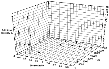
These results are shown graphically in Figures 1 and 2.
5 Example 8
The SWCTT tests of Examples 1-7 were repeated with a number of different sized
slugs of the aqueous displacement fluid (injection water) of analysis Ca 1.47
ppm/Mg 0
ppm/Divalent TDS 10 ppm. The connate water contained Ca 320 ppm/Mg 48
ppm/Divalents 398 ppm/TDS 31705 ppm giving the divalent fraction of 0.003. The
oil had
an API gravity of 23 . The formation contained 13.8% kaolinite.
Produced water, which was the connate water in the test, was passed into the
formation first, giving an So, of 0.42. A slug of 0.2 PV of the injection
water was then
passed giving an So, of 0.42 followed by a repeat slug of the produced water.
A slug of 0.4
PV of the injection water was then passed giving an So, of 0.27, followed
again by a slug of
the produced water. The So, was at 0.27 after a slug of 0.7 PV of the
injection water was
=
-_.7k1/11h 71111X THH 15.4U FAX 01932762388 444 Ann yonnirh
_
'Printed: 21/07/2008i DESCPA M
GJE3399,1003337'
,
'
= Case No. 10405(2) 18
passed again followed by produced water. The Pore Volume, PV, was determined
from
modelling studies.
Example 9
The SWCTT tests of Ex 8 were repeated with a number of different sized slugs
of
the aqueous displacement fluid (injection water) of analysis Ca 30 ppm/Mg 6
'
ppm/Divalent 37 ppm TDS. The connate water was the same as in Ex 8 giving the
divalent .
fraction of 0.09. The oil had a density of 0Ø159 g/m1 (an API gravity of 23
). The
formation contained 12.2% kaolinite. .
Produced water, which was the connate water in the test, was passed into the
formation first, giving an So, of 0.41. A slug of 0.2 PV of the injection
water was then
passed giving an Sof of 0.37, followed by a repeat slug of the produced water.
A slug of
0.3 PV of the injection water was then passed giving an So, of 0.30, followed
again by a
slug of the produced water. The Pore Volume, PV, was determined by modelling
studies.
Example 10
= 15 The following studies utilized a coreflood facility which
operates at reservoir
= conditions, of up to 150 C and 6.89x10⁷ Pa (10,000 psi). The equipment of
the coreflood
facility has an in-situ saturation monitor (described below) and uses live
fluids (reservoir =
= fluids that are equilibrated with reservoir gas) both for ageing and
fluid flow. Volumetric= .
production is measured at the reservoir conditions using an in-line separator.
Saturations
during and at the end of the flood are assured by measuring the amount of the
pore space
occupied by radioactively doped brine. The in-situ saturation monitor not only
determines . .
the saturation but also provides a quantitative analysis of the integrity of
the slug, due to =
the difference in capture cross section between high salinity radioactively-
doped brines and =
low salinity brines.
Core Preparation
Core plug samples, nominally 7.62 cm (3") long by 3.81 cm (1.1/2") in diameter
were used for this study. The samples were first restored i.e. the samples
were cleaned .
using miscible solvents such that they were as close to being in a ¨water wet"
condition as
possible. After cleaning, the samples were placed in hydrostatic coreholders
and were
saturated with a simulated formation water (brine) by flowing the water
through the core
plugs under a back pressure. After a throughput of approximately 10 pore
volumes of
- CA 02662295 2009-03-02
P
9 ived at the EPO on May 29,2008 16:08:40. P. AMENDED SHEET
29/05/2008-
CA 02662295 2009-03-02
'714/iih "1"4 1N11 isinu FAA 01932762388 444 Ann minich
Pi:Mc/WO
t,,nted: 21/07/2008 V DESCPAMD V
GB20070033371
=
' Case No. 10405(2) 18a
brine, the samples were removed from the hydrostatic coreholders and the
initial water
saturation was set up
=
=
=
=
=
=
=
1
=
V=
10 ',/ed at the EPO on May 29, 2008 16:08:40. P AMENDED SHEET
29/05/20081 I
CA 02662295 2009-03-02
WO 2008/029124
PCT/GB2007/003337
19
in each sample using the procedure described below.
Acquisition of Initial Water Saturation.
It was essential that the core plug sample had a representative initial water
saturation (S,,i) value which was matched to the water saturation at the
height above the oil
water contact in the reservoir. The initial water saturation for each sample
was achieved
by porous plate de-saturation, using the strongly non-wetting gas, nitrogen.
Once the
initial water saturations were acquired, the samples were loaded into
hydrostatic
coreholders and saturated by flowing refined oil through the samples under
back pressure.
In-situ saturation monitoring was used to provide distributed saturation data
to aid
interpretation of experimental results. This technique was based on the linear
attenuation
of y-rays using a 'y-ray source and detector. Each source/detector pair viewed
a slice of
core having a width of 4 mm. A linear relationship exits between the log of
counts
(transmitted flux of y-rays) and water saturation. Therefore, by employing
careful
calibration procedures for each source/detector assembly, fluid saturation
could be
calculated during oil/high salinity brine displacements and at the end of each
low salinity
slug. A number of these assemblies were mounted along the core plug samples so
that
water saturation was monitored at fixed positions versus time/throughput
during the
waterfloods.
Two sets of calibration data were collected for each source/detector pair at
the end
of each waterflood. 100% high salinity brine saturation calibrations were
recorded at the
end of the cleaning stage. 100% oil saturation calibrations were measured with
the core
100% saturated with live crude oil at the end of the tests.
In these experiments it was necessary to replace chloride ions in the high
salinity
sea water injection brines with iodide ions so that the contrast between the
aqueous and
oleic phases was increased during the in-situ saturation monitoring. This
reduced the noise
to signal ratio, and improved the accuracy of the calculated in-situ
saturations. The
molarity of the doped brine was kept the same as the un-doped brine to ensure
that no
adverse rock/fluid interactions occurred.
Ageing Process
Samples were loaded into "reservoir condition" coreholders and slowly raised
in
pressure and temperature to reservoir conditions. Reservoir temperature was
130 C.
The refined oil was miscibly displaced at reservoir conditions by live crude
oil to
`7L1/(1C 'Ping `111111 15'07 FAX 01932762388 444 Ann mirnirh
17101R/1119
Printed : .,21/07/200)L PO,
211S1337:,i C)t¨E, SCPAMID
Case No. 10405(2) 20
=
constant gas to oil ratio, via a slug of toluene. Thus, a slug of toluene is
injected into the
sample before injecting the crude oil. The toluene is miscible with both the
refined oil and
the crude oil and therefore allows the refined oil to be readily displaced by
the crude oil.
When the differential pressure was stable, the live crude oil viscosity and
effective
permeability to live crude oil was measured. The sample was then. aged in live
crude oil
for three weeks. By live crude Oil is meant dead (degassed) crude oil that has
been
recombined with its associated gas. During the ageing period the live crude
oil was :
replaced every"few days. A minimum of one pore volume of live crude oil was
injected
and a sufficient amount was used to achieve a constant pressure drop across
the sample and
a constant gas to oil ratio.
= Waterflooding Procedures to High Salinity Remaining Oil Saturation
= Unsteady state waterfloods were carried out on the samples at reservoir
conditions "
using in-situ saturation monitoring.. In-situ saturations were used to provide
data on the Oil
distributions which developed during the course of the waterflood.
Low rate waterfloods using a brine (seawater) were carried out on restored
samples
at a typical reservoir advancement rate of 1 foot per day (0.3048 metres per
day), typically
corresponding to 4 cm3/hour in the laboratory: During the injection of the
brine, oil =
production and pressure drop were continuously monitored. Oil production Was
recorded
at reservoir conditions in an ultrasonic separator. This had the advantage of
directly
measuring oil production at reservoir conditions. The high salinity water
flood was
= continued for a throughput of approximately 15 PV.
The brine was pre-equilibrated to the reservoir pore pressure using separator
gas
(i.e. gas that was separated from the crude oil at a production facility).
This ensured that
there was no gas transfer from the oil to the water phase that could result in
oil shrinkage in
the plug sample during the reservoir condition tests.
Low Salinity Water Slug Iniection
The remaining oil saturation following the high salinity water flood was
measured.
1..
Slugs of low salinity injection water of 0.1, 0.2, 0.3, 0.4, 0.5, 0.75 and 1
PV were injected,
sequentially. The low salinity brine composition is given in Table 3. together
with the
composition of the connate water and the composition of the high salinity
brine (seawater).
All low salinity brines were pre-equilibrated with separator gas, as described
previously:
=
¨ CA 02662295 2009-03-02
11 lied at the EPO on May 29, 2008 16:08:40. p; AMENDED SHEET
29/05/2008
CA 02662295 2009-03-02
WO 2008/029124
PCT/GB2007/003337
21
Table 3¨ Composition of the low salinity brine
Salt SrC12 NaHCO3 Na2S 04 CaC12 MgC12 KC1 NaC1 Na!
6H20 Ong/0 (mg/1) 6H20 6H20 (mg/1) (mg/1) (mg/1)
(mg/1) (ng/1) (ng/1)
Sea 0 191 3,917 2,186 10,640 725
3,983 50,000
Water
Connate 1,372 228 0 30,610 5,027 932
54,720 50,000
Water
Low 4.17 85.4 47.6 232 15.8 511.8 0
salinity
Injection
Water
In-situ saturation data were used to determine the stability of the slug of
low
salinity injection water and the .oil volume produced using each slug size.
Results and Discussion
It was found that a 0.3 pore volume slug of the low salinity injection water
passes
from the inlet to the outlet of the "reservoir condition" coreholder without
dispersion
(across a 7.5 cm plug sample). A 0.1 PV slug disperses by the time the low
salinity water
has reached 10% into the core plug sample. A 0.2 PV slug reaches about 30%
into the core
= plug sample before it disperses.
The cumulative oil volumes that are produced when injecting the slugs of low
salinity water are presented in Table 4. The 0.1 PV slug does not produce any
incremental
oil. This is as expected since the slug does not sweep any of the core plug
sample. The 0.2
PV slug produces a small amount of additional oil. This additional oil is
attributed to
mobilization of oil in the portion of the core sample close to the inlet of
the core holder.
The 0.3 PV slug produces a large amount of the incremental oil, and the 0.4 PV
slug
produces close to 95% of the total incremental oil production.
25
CA 02662295 2009-03-02
WO 2008/029124
PCT/GB2007/003337
22
Table 4¨ Cumulative Oil Production with Injected Low Salinity Water
Pore volume of injected low salinity water Cumulative oil produced, pore
volumes
0.1 0
0.2 0.005
0.3 0.044
0.4 0.064
0.5 0.064
0.6 0.069
0.75 0.069
1 0.073
10
20