Note: Descriptions are shown in the official language in which they were submitted.
CA 02662815 2009-03-06
WO 2008/054583 PCT/US2007/020710
NON-WOVEN COMPOSITE
Background
[0001] The present invention generally relates to non-woven materials
with a voluminous z direction component which have a surface skin and a
woven, knitted, or non-woven layer added on either one or both sides of the
voluminous non-woven.
[0002] There are a number of products in various industries, including
automotive, office and home furnishings, construction, and others; that
require
materials having a z-direction thickness to provide thermal, sound insulation,
aesthetic, and other performance features. In many of these applications it is
also required that the material be thermoformable to a specified shape and
rigidity. In the automotive industry these products often are used for
shielding
applications such as noise and thermal barriers in automotive hood liners and
firewall barriers. These automotive materials may or may not have an aesthetic
cover material incorporated into the part, which can also protect the core
from
abrasion, etc. In home and office furnishing, and construction applications
these
materials are often used as structural elements to which exterior decorative
materials might be added. Additionally, these and other industries require
that
the materials deliver these properties in a cost effective manner.
[0003] Often the barrier properties are best accomplished by using
specialty fibers and or materials that generate a high level of performance,
but
also introduce significant cost to the substrate. Especially in a voluminous
thickness substrate, the introduction of even a small percent of these
materials
into the shield material can introduce a significant level of cost to the
overall
substrate. For this reason composites having specialty surface layers are
often
used to provide these barrier properties. An example would be a thin layer of
high cost but highly effective specialty material laminated to a voluminous
lower
cost core material. While the resulting composite costs less than more
homogenous composites, there are disadvantages such as the need for
additional processing steps and the potential delamination of the skin layer.
Page 1 of 30
CA 02662815 2009-03-06
WO 2008/054583 PCT/US2007/020710
[0004] The present invention is an alternative to the prior art. It is a non-
woven material with different functional zones to provide various desired
properties of the material localized to the vertically oriented zones where
required. Low melt fibers that can be used to construct a "skin" on one, or
both,
planar sides of the non-woven material can be localized to the sides of the
material specifically. The formation of this skin and the addition of woven,
non-
woven, and knitted fabric layers can provide a barrier between the atmosphere
and the interior of the non-woven material, can provide a smoother more
aesthetically pleasing surface, and can improve other performance features
such
as abrasion, sound absorption, and rigidity. The invention has superior
molding
performance because the low melt fibers can be not only optimized in quantity
for superior performance, but can also be localized to optimize performance
for
specific mold design. This forms an I-beam like structure, giving rigidity and
strength to the composite. Superior acoustic properties can be achieved by
creating a distinct skin and additional fabric layers on the surface zones of
the
non-woven material with a lower air permeability than the core. By using low
melt fibers of the same chemical nature as the voluminous core, an essentially
single recyclable material can be achieved. All of these benefits are achieved
at
competitive costs and weight compared to the existing products.
Brief Description of the Drawings
[0005] These and other features, aspects, and advantages of the present
invention will become better understood with regard to the following
description,
appended claims, and accompanying drawings where:
FIG. 1 shows a cross-section of one embodiment of a non-woven material
of the present invention;
FIG. 2 shows a cross-section of another embodiment of a non-woven
material of the present invention;
FIG. 3 shows a cross-section of yet another embodiment of a non-woven
material of the present invention;
FIG. 4 shows a diagram of a machine for performing a process for forming
the non-woven material of the present invention; and,
Page 2 of 30
CA 02662815 2009-03-06
WO 2008/054583 PCT/US2007/020710
FIGS. 5-19 show cross-sections of other embodiments of a non-woven
composite of the present invention.
Detailed Description
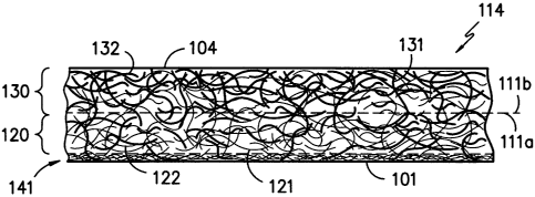
[0006] Referring now to the figures and in particular to FIG. 1, there is
shown an enlarged cross-sectional view of a non-woven material 100
illustrating
an embodiment of the present invention. In one embodiment, the non-woven
material 114 generally includes first binder fibers 121, first effect fibers
122, and
second binder fibers 131. In another embodiment, the non-woven material 114
also includes second effect fibers 132.
[0007], As used herein, binder fibers are fibers that form an adhesion or
bond with the other fibers. Binder fibers can include fibers that are heat
activated. Examples of heat activated binder fibers are fibers that can melt
at
lower temperatures, such as low melt fibers, core and sheath fibers with a
lower
sheath melting temperature, and the like. In one embodiment, the binder fibers
are a polyester core and sheath fiber with a lower melt temperature sheath. A
benefit of using a heat activated binder fiber as the second binder fiber 131
in
the non-woven material 114, is that the material can be subsequently molded to
part shapes for use in automotive hood liners, engine compartment covers,
ceiling tiles, office panels, etc.
[0008] As used herein, effect fibers are any additional fibers which may
be beneficial to have located in the respective zone, or concentrated near the
respective surface. These effect fibers may be used to impart color or
functionality to the surface. Effective fibers of color can give the non-woven
material the desired aesthetic appearance. These effect fibers can also
include
performance fibers such as chemical resistant fibers (such as polyphenylene
sulfide and polytetrafluoroethylene), moisture resistant fibers (such as
polytetrafluoroethylene and topically treated materials like polyester), fire
retardant fibers, or others.
[0009] As used herein, fire retardant fibers shall mean fibers having a
Limiting Oxygen Index (LOI) value of 20.95 or greater, as determined by ISO
4589-1. Types of fire retardant fibers include, but are not limited to, fire
Page 3 of 30
CA 02662815 2009-03-06
WO 2008/054583 PCT/US2007/020710
suppressant fibers and combustion resistant fibers. Fire suppressant fibers
are
fibers that meet the LOI by consuming in a manner that tends to suppress the
heat source. In one method of suppressing a fire, the fire suppressant fiber
emits a gaseous product during consumption, such as a halogenated gas.
Examples of fiber suppressant fibers include modacrylic, PVC, fibers with a
halogenated topical treatment, and the like. Combustion resistant fibers are
fibers that meet the LOI by resisting consumption when exposed to heat.
Examples of combustion resistant fibers include silica impregnated rayon such
as rayon sold under the mark VISIL , partially oxidized polyacrylonitrile,
polyaramid, para-aramid, carbon, meta-aramid, melamine and the like.
[0010] In one embodiment, the first effect fibers 122 are a bulking fiber.
Bulking fibers are fibers that provide volume in the z direction of the non-
woven
material, which extends perpendicularly from the planar dimension of the non-
woven material 114. Types of bulking fibers would include fibers with high
denier per filament (5 denier per filament or larger), high crimp fibers,
hollow-fill
fibers, and the like. These fibers provide mass and volume to the material.
Examples of fibers used as first effect fibers 122 include polyester,
polypropylene, and cotton, as well as other low cost fibers.
[0011] The non-woven material 114 includes a first planar zone 120 and
a second planar zone 130. The first planar zone 120 has a first boundary plane
101 located at the outer surface of the non-woven material 114, and a first
zone
inner boundary plane 111 a located nearer to the second planar zone 130 than
the first boundary plane 101. The second planar zone 130 has a second
boundary plane 104 located at the outer surface of the non-woven material 114
and a second zone inner boundary plane 111 b located nearer to the fire
retardant planar zone 120 than the second soundary plane 104. The non-woven
material 114 is a unitary material, and the boundaries of the two zones do not
represent the delineation of layers, but rather areas within the unitary
material.
Because the non-woven material 114 is a unitary material, and the first planar
zone 120 and the second planar zone 130 are not discrete separate layers
joined together, various individual fibers will occur in both the first planar
zone
120 and the second planar zone 130. Although FIG. 1 illustrates the first
planar
Page 4 of 30
CA 02662815 2009-03-06
WO 2008/054583 PCT/US2007/020710
zone 120 as being a smaller thickness in the z-direction than the second
planar
zone 130, the relative thickness of the two zones can be different than as
shown.
[0012] The first planar zone 120 contains first binder fibers 121, first
effect fibers 122, and second binder fibers 131, (and optionally second effect
fibers 132). The first planar zone 120 has a greater concentration of the
first
binder fibers 121 than the second planar zone 130. Additionally, the
distribution
of the fibers in the first planar zone 120 is such that the concentration of
the first
binder fibers 121 is greater at the first boundary plane 101 of the first
planar
zone 120 than the first zone inner boundary plane 111a. Moreover, it is
preferred that the concentration of the first binder fibers 121 decreases in a
gradient along the z-axis from the first boundary plane 101 to the first zone
inner
boundary plane 111 a.
[0013] The second planar zone 130 also contains second binder fibers
121, first effect fibers 122, and second binder fibers 131, (and optionally
second
effect fibers 132). As such, the second planar zone 130 has a greater
concentration of the second binder fibers 131 than the first planar zone 120.
Additionally, the distribution of the fibers in the second planar zone 130 is
such
that the concentration of the second binder fibers 131 is greater at the
second
boundary plan 104 than the second zone inner boundary plane 111 b.
Additionally, it is preferred that the concentration of the second binder
fibers 131
decreases in a gradient along the z-axis from the second boundary plane 104 to
the second zone inner boundary plane 111 b.
[0014] The first effect fibers 122 are about the same denier as the first
binder fibers 121 or larger, but smaller than the second binder fiber 131.
When
the first effect fibers 122 are about the same denier as the first binder
fibers 121,
the first effect fibers 122 have the same distribution and gradient along the
z-axis
as the first binder fibers 121. When the first effect fibers 122 have a larger
denier than the first binder fibers 121, the concentration of the first effect
fibers
122 increases in a gradient from the first boundary plane 101 to a inner
location
in the non-woven material 114, and then the concentration of the first effect
Page 5 of 30
CA 02662815 2009-03-06
WO 2008/054583 PCT/US2007/020710
fibers 122 decreases in a gradient from that inner location to the second
boundary plane 104.
[0015] In the embodiment of the present invention having the second
effect fiber 132, the second effect fibers 132 are about the same size as the
second binder fiber 131 or smaller, but larger than the first binder fibers
121.
When the second effect fibers 132 are about the same denier as the second
binder fibers 131, the second effect fibers 132 have the same distribution and
gradient along the z-axis as the second binder fibers 131. When the second
effect fibers 132 have a smaller denier than the second binder fibers 131, the
concentration of the second effect fibers 132 increases in a gradient from the
second boundary plane 104 to a inner location in the non-woven material 100,
and then the concentration of the second effect fibers 122 decreases in a
gradient from that inner location to the first boundary plane 101.
[0016] Referring now to FIG. 2, there is shown a cross-sectional view of a
non-woven 110 illustrating another embodiment of the present invention. As
illustrated, the non-woven material 112 generally includes the first binder
fibers
121, the first effect fibers 122, the second binder fibers 131, and optionally
the
second effect fibers 132, as described with reference to the non-woven
material
114 in FIG. 1. Also similar to the non-woven material 114, the non-woven
material 112 includes first boundary plane 101, a second boundary plane 104, a
first planar zone 120, a second planar zone 130, a first zone inner boundary
plane 111 a, and a second zone inner boundary plane 111 b. The first planar
zone 120 in the non-woven material 112 contains the first binder fibers 121,
the
first effect fibers 122, the second binder fibers 131, and optionally the
second
effect fibers 132 in the same relative weight, concentrations, and
distributions as
describe with respect to the first planar zone 120 of the non-woven material
114
in FIG. 1. The second planar zone 130 in the non-woven material 112 contains
the first binder fibers 121, the first effect fibers 122, the second binder
fibers 131,
and optionally the second effect fibers 132 in the same relative weight,
concentrations, and distributions as describe with respect to the second
planar
zone 130 of the non-woven material 114 in FIG. 1. However, the non-woven
Page 6 of 30
CA 02662815 2009-03-06
WO 2008/054583 PCT/US2007/020710
material 112 does not include the first surface skin 141 as shown with the non-
woven material 114 of FIG. 1.
[0017] Still referring to FIG. 2, in addition to the common elements that
the non-woven material 112 has with the non-woven material 114, the non-
woven material also includes a second surface skin 140 along the second
boundary plane 104. The second surface skin 140 contains second binder fibers
131, wherein the second binder fibers 131 are melt-bonded into the semi-rigid
skin. The second surface skin 140 can also contain the first binder fiber 121,
the
first effect fiber 122, and the optional second effect fibers 132. However,
the
second surface skin 140 will contain lesser amounts of the first binder fiber
121
or the first effect fiber 122 than the second binder fiber 131 or the optional
second effect fiber 132 (not shown).
[0018] Referring now to FIG. 3, there is shown a cross-sectional view of a
non-woven 110 illustrating another embodiment of the present invention. As
illustrated, the non-woven material 110 generally includes the first binder
fibers
121, the first effect fibers 122, the second binder fibers 131, and optionally
the
second effect fibers 132 (not shown), as described with reference to the non-
woven material 114 in FIG. 1. Also similar to the non-woven material 114, the
non-woven material 110 includes first boundary plane 101, a second boundary
plane 104, a first planar zone 120, a second planar zone 130, a first zone
inner
boundary plane 111 a, and a second zone planar inner boundary plane 111 b.
The first planar zone 120 in the non-woven material 110 contains the first
binder
fibers 121, the first effect fibers 122, the second binder fibers 131, and the
optional second effect fibers 132 in the same relative weight, concentrations,
and
distributions as describe with respect to the first planar zone 120 of the non-
woven material 114 in FIG. 1. The second planar zone 130 in the non-woven
material 110 contains the first binder fibers 121, the first effect fibers
122, the
second binder fibers 131, and optionally the second effect fibers 132 in the
same
relative weight, concentrations, and distributions as describe with respect to
the
second planar zone 130 of the non-woven material 114 in FIG. 1.
[0019] Still referring to FIG. 3, in addition to the common elements that
the non-woven material 110 has with the non-woven material 112 of FIG. 2, the
Page 7 of 30
CA 02662815 2009-03-06
WO 2008/054583 PCT/US2007/020710
non-woven material 110 also includes a first surface skin 141 along the first
boundary plane 101 and a second surface skin 140 along the second boundary
plane 104. The first surface skin 141 in the non-woven material 110 has the
same fibers and properties as the first surface skin 141 in the non-woven
material 114 of FIG. 1, and the second surface skin 140 in the non-woven
material 110 has the same fibers and properties as the first surface skin 140
in
the non-woven material 112 of FIG. 2.
[0020] Referring now to FIG. 4, there is shown a diagram illustrating a
process for forming the non-woven material 114 from FIG. 1, the non-woven
material 112 from FIG. 2, or the non-woven material 110 from FIG. 3. As
illustrated in FIG. 4, air lay equipment 400 uses differences in the fibers to
lay
the fibers on a collection belt 430 with the concentration of each type of
fiber
varying in the z-direction, which is perpendicular to the plane of the non-
woven
material 114, 112, 110, as it lays on the collection belt 430. A commercially
available piece of equipment that has been found satisfactory in this process
to
form the claimed invention is the "K-12 HIGH-LOFT RANDOM CARD" by Fehrer
AG, in Linz, Austria.
[0021] Still referring to FIG. 4, in one embodiment, the varying
concentration of the fibers in the non-woven material is accomplished by using
fibers types having different deniers, which results in the different fibers
collecting on the collection belt 430 primarily at different locations. The
fibers are
projected along the collection belt 430 in the same direction as the travel
direction of the collection belt 430. Fibers with a larger denier will tend to
travel
further than smaller denier fibers down the collection belt 430 before they
fall to
the collection belt 430. As such, there will tend to be a greater
concentration of
the smaller denier fibers closer to the collection belt 430 than larger denier
fibers.
Also, there will tend to be a greater concentration of the larger denier
fibers
farther from the collection belt 430 than smaller denier fibers.
[0022] Referring now to FIGS. 1, 2, 3, and 4, the first binder fibers 121
and the first effect fibers 122 have a smaller denier per filament than the
second
binder fibers 131 and the optional second effect fibers 132. It has been found
that a good distribution of binder fibers in the non-woven material can be
Page 8 of 30
CA 02662815 2009-03-06
WO 2008/054583 PCT/US2007/020710
accomplished by the first binder fibers 121 having a denier ranging from about
1
to about 4 deniers and the second binder fibers 131 having a denier greater
than
about 4 denier.
[0023] Selection of the denier of the various fibers must be such that the
difference in the denier between the fibers primarily in the first zone 120
with the
fibers primarily in the bulking zone 130 is sufficient to create the desired
distribution and gradient of the fibers in the non-woven material 114, 112,
110.
In one embodiment, the difference between the denier of fibers primarily in
bulking zone 130 is at least about two times (2X) the denier or greater than
the
denier of the fibers primarily in the first zone 120. Preferably, the first
binder
fiber 121, the first effect fiber 121, the second binder fiber 131, and
optionally the
second effect fiber 132, are staple fibers having a length of from about 1
inch to
about 3.5 inches, and more preferably from about 1.5 inches to about 2.5
inches.
[0024] The first binder fibers 121, the first effect fibers 122, and the
second binder fibers 131 are opened and blended in the appropriate proportions
and delivered to a cylinder 420. In an embodiment with the optional second
effect fibers 132, the second effect fibers 132 are also opened and blended
with
the first binder fibers 121, the first effect fibers 122, and the second
binder fibers
131. The cylinder 420 rotates and throws the blended fibers towards the
collection belt 430 whereby the fibers are collected as they fall from the
throwing
pattern. The spinning rotation of the cylinder 420 is such that larger denier
fibers
tend to travel further than the smaller denier fibers in the direction of
travel for
the collection belt 430 before resting on the collection belt 430. Therefore,
the
web 100' of fibers collected on the collection belt 430 will have greater
concentration of the smaller denier fibers in the z-direction adjacent to the
collection belt 430 at the web first surface 101', and a greater concentration
of
the larger denier fibers in the z-direction further away from the collection
belt 430
at the web second surface 104'.
[0025] Inherent in the process of forming the web 100' is the progressive
decrease, or gradient, in the concentration of the first binder fibers 121,
where
the concentration of the first binder fibers 121 continuously decreases as a
function of the distance from the web first surface 101', adjacent to the
collection
Page 9 of 30
CA 02662815 2009-03-06
WO 2008/054583 PCT/US2007/020710
belt 430, moving towards the opposite or web second surface 104'. Also
inherent in the process of forming the web 100' is the progressive decrease,
or
gradient, in the concentration of the second binder fibers 131, where the
concentration of the second binder fibers 131 continuously decreases as a
function of the distance from the web second surface 104' moving towards the
opposite or web first surface 101'.
[0026] After the non-woven web 100' is formed, it can be heated so that
the first binder fibers 121 and the second binder fibers 131 at least
partially melt
bond with at least a portion of the other fibers. This heating step stabilizes
the
non-woven web 100' until the process can be completed to form the non-woven
material 114, 112, 110 or subsequent composite structures. However, it is
contemplated that the heating step to stabilize the non-woven web 101' can be
conducted simultaneously with the step of forming of the skin 141, 140 of the
non-woven material 114, 112, 110, as disclosed below, by using the same heat
source that creates the skin 141.
[0027] In the embodiment of the non-woven material 114 illustrated in
FIG. 1, the web first surface 101' of the non-woven web 101' is subjected to a
heat treatment, such as a calendar or a heated belt, which causes the first
binder
fibers 121 at the web first surface 101' to fuse together and with the other
fibers
in the web first surface 101' to form a film-like surface or skin. The skin
surface
formed on the web first surface 101' is first skin 141 of the non-woven
material
114. The fusing of material at the first boundary plane 101 to form the first
skin
141, creates a non-woven material 114 with reduced air permeability, improved
sound absorption, increased abrasion resistance, and increased rigidity as
compared to similar material without a fused skin.
[0028] In the embodiment of the non-woven material 112 illustrated in
FIG. 2, the web second surface 104' of the non-woven web 101' is subjected to
a
heat treatment, such as a calendar or a heated belt, which causes the second
binder fibers 131 at the web second surface 104' to fuse together and with the
other fibers in the web second surface 104' to form a film-like surface or
skin.
The skin surface formed on the web second surface 104' is the second skin 140
of the non-woven material 112. The fusing of material at the web second
Page 10 of 30
CA 02662815 2009-03-06
WO 2008/054583 PCT/US2007/020710
surface 101 to form the second skin 140, creates a non-woven material 112 with
reduced air permeability, improved sound absorption, and increased abrasion
resistance as compared to similar material without a fused skin.
[0029] In the embodiment of the non-woven material 110 illustrated in
FIG. 3, the web first surface 101' and the web second surface 104' of the non-
woven web 100' are each subjected to a heat treatment, such as a calendar or a
heated belt. In one embodiment, the non-woven web 101' is heat treated
between a pair of heated belts, such as a laminator, to simultaneously heat
the
web first surface 101' and the web second surface 104'. The heat treatment at
the web first surface 101' causes the first binder fibers 121 at the web first
surface 101' to fuse together with the other fibers in the web first surface
101' to
form a film-like surface or skin. The skin surface formed on the web first
surface
101' is the first skin 141 of the non-woven material 110. The heat treatment
at
the web second surface 104' causes the second binder fibers 131 at the web
second surface 104' to fuse together and with the other fibers in the web
second
surface 104' to form a film-like surface or skin. The skin surface formed on
the
web second surface 104' is the second skin 140 of the non-woven material 110.
The fusing of material at the web first surface 101' and the web second
surface
104' to form the first skin 141 and the second skin 140, respectively, creates
a
non-woven material 110 with reduced air permeability, improved sound
absorption, and increased abrasion resistance as compared to similar material
without a fused skin.
[0030] Still referring to FIGS. 1, 2, 3, and 4, the web first surface 101' and
the web second surface 104' correlate to the first boundary plane 101 and the
second boundary plane 104, respectively, of the non-woven material 100, 200,
300. The distribution of the first binder fibers 121, the first effect fibers
122,
second binder fibers 131, and optionally the second effect fibers 132 in the
non-
woven web 101' is the same as the distribution of those same fibers in the non-
woven material 100, 200, 300. It is this same distribution of fibers by the
equipment 400 that creates the first planar zone 120 and the second planar
zone
130 of the non-woven material 100, 200, 300.
Page 11 of 30
CA 02662815 2009-03-06
WO 2008/054583 PCT/US2007/020710
[0031] Referring now to FIG. 5, there is shown a cross-sectional view of a
non-woven composite 500 illustrating an embodiment of the present invention.
As illustrated, the non-woven composite 500 includes the non-woven material
110 which generally includes the first binder fibers 121, the first effect
fibers 122,
the second binder fibers 131, and optionally the second effect fibers 132, as
described with reference to the non-woven material 110 in FIG. 3. Also similar
to
the non-woven material 110 of FIG.3, the non-woven material 110 of the non-
woven composite 500 includes first boundary plane 101, a second boundary
plane 104, a first planar zone 120, a second planar zone 130, a first zone
inner
boundary plane 111 a,. and a second zone planar inner boundary plane 111 b.
The first planar zone 120 in the non-woven material 110 contains the first
binder
fibers 121, the first effect fibers 122, the second binder fibers 131, and
optionally
the second effect fibers 132 in the same relative weight, concentrations, and
distributions as describe with respect to the first planar zone 120 of the non-
woven material 110 in FIG. 3. The second planar zone 130 in the non-woven
material 110 contains the first binder fibers 121, the first effect fibers
122, the
second binder fibers 131, and optionally the second effect fibers 132 in the
same
relative weight, concentrations, and distributions as describe with respect to
the
second planar zone 130 of the non-woven material 110 in FIG. 3. The non-
woven material 110 also includes a first surface skin 141 along the first
boundary
plane 101 and a second surface skin 140 along the second boundary plane 104.
While FIG. 5 is described with non-woven material 110 of FIG. 3 with skin
layers
141, 140 on either side of the non-woven material 110, non-woven composite
500 may be formed with non-woven materials 114, 112 with only a skin layer on
one side of the non-woven material.
[0032] In the embodiment of the present invention illustrated in FIG. 5, a
stiffening layer 160 is secured along the first boundary plane 101 of the non-
woven layer 110 by an adhesive layer 150. The adhesive layer 150 may be any
suitable material that will secure the stiffening layer(s) or knit or woven
layer(s) to
the non-woven material 110. In one embodiment, the adhesive layer 150 is a
non-woven layer made by interlocking the fibers or filaments. Preferably, the
adhesive layer is made of low melt polyester (PET) fibers. However, the
Page 12 of 30
CA 02662815 2009-03-06
WO 2008/054583 PCT/US2007/020710
adhesive layer may also be extruded, sprayed, or powder coated onto the
composite. The adhesive layer preferably has a melting temperature of about
160 - 200 C. The adhesive layer 150 is typically much thinner than the non-
woven material 110.
[0033] The stiffening layer 160 located on the adhesive layer 150 and is a
non-woven with a high tenacity then the non-woven material 110. This
stiffening
layer 160 can be non-woven such as a spun bond, spun lace, needle punch, air
laid, wet laid, pattern bond non-woven. The stiffening non-woven layer 160 may
be made of any natural or man-made fibers suitable to the composite, including
polyester, cotton, polyester/cotton blends, nylon, polyarylenes, olefin fibers
such
as polyethylene and polypropylene, FR (fire resistant) fibers such as
modacrylic,
VisilT'" (silica modified rayon), partially oxidized acrylonitrile (PAN),
spandex
yarns, rayon, and FR treated yarns of above. The stiffening non-woven layer
160 may be printed before of after application to the composite. In one
embodiment, the stiffening non-woven layer 160, 162 may have a weight of
about 0.5 oz/yd2 to about 2 oz/yd2.
[0034] Referring now to FIG. 6, there is shown a cross-sectional view of a
non-woven composite 600 illustrating an embodiment of the present invention.
As illustrated, the non-woven composite 600 includes the non-woven material
110 which generally includes the first binder fibers 121, the first effect
fibers 122,
the second binder fibers 131, and optionally the second effect fibers 132, as
described with reference to the non-woven material 110 in FIG. 3. Also similar
to
the non-woven material 110 of FIG.3, the non-woven material 110 of the non-
woven composite 500 includes first boundary plane 101, a second boundary
plane 104, a first planar zone 120, a second planar zone 130, a first zone
inner
boundary plane 111 a, and a second zone planar inner boundary plane 111 b.
The first planar zone 120 in the non-woven material 110 contains the first
binder
fibers 121, the first effect fibers 122, the second binder fibers 131, and the
optional second effect fibers 132 in the same relative weight, concentrations,
and
distributions as describe with respect to the first planar zone 120 of the non-
woven material 110 in FIG. 3. The second planar zone 130 in the non-woven
material 110 contains the first binder fibers 121, the first effect fibers
122, the
Page 13 of 30
CA 02662815 2009-03-06
WO 2008/054583 PCT/US2007/020710
second binder fibers 131, and optionally the second effect fibers 132 in the
same
relative weight, concentrations, and distributions as describe with respect to
the
second planar zone 130 of the non-woven material 110 in FIG. 3. The non-
woven material 110 also includes a first surface skin 141 along the first
boundary
plane 101 and a second surface skin 140 along the second boundary plane 104.
While FIG. 6 is described with non-woven material 110 of FIG. 3 with skin
layers
141, 140 on either side of the non-woven material 110, the non-woven
composite 600 may be formed with non-woven materials 114, 112 with only a
skin layer on one side of the non-woven material.
[0035] In the embodiment of the present invention illustrated in FIG. 6, a
first stiffening layer 160 is secured along the first boundary plane 101 of
the non-
woven layer 110 by the binder fibers in the first surface skin 141 of the non-
woven material 110 and/or the fibers in the stiffening layer 160. The binder
fibers in the first surface skin 141 and/or the fibers in the stiffening layer
160
secure the stiffening layer 160 to the first boundary plane 101 by a melt
bond.
[0036] Referring now to FIG. 7, there is shown a cross-sectional view of a
non-woven composite 700 illustrating an embodiment of the present invention.
As illustrated, the non-woven composite 700 includes the non-woven material
110 which generally includes the first.binder fibers 121, the first effect
fibers 122,
the second binder fibers 131, and optionally the second effect fibers 132, as
described with reference to the non-woven material 110 in FIG. 3. Also similar
to
the non-woven material 110 of FIG.3, the non-woven material 110 of the non-
woven composite 500 includes first boundary plane 101, a second boundary
plane 104, a first planar zone 120, a second planar zone 130, a first zone
inner
boundary plane 111 a, and a second zone planar inner boundary plane 111 b.
The first planar zone 120 in the non-woven material 110 contains the first
binder
fibers 121, the first effect fibers 122, the second binder fibers 131, and
optionally
the second effect fibers 132 in the same relative weight, concentrations, and
distributions as describe with respect to the first planar zone 120 of the non-
woven material 110 in FIG. 3. The second planar zone 130 in the non-woven
material 110 contains the first binder fibers 121, the first effect fibers
122, the
second binder fibers 131, and optionally the second effect fibers 132 in the
same
Page 14 of 30
CA 02662815 2009-03-06
WO 2008/054583 PCT/US2007/020710
relative weight, concentrations, and distributions as describe with respect to
the
second planar zone 130 of the non-woven material 110 in FIG. 3. The non-
woven material 110 also includes a first surface skin 141 along the first
boundary
plane 101 and a second surface skin 140 along the second boundary plane 104.
While FIG. 7 is described with non-woven material 110 of FIG. 3 with skin
layers
141, 140 on either side of the non-woven material 110, non-woven composite
700 may be formed with non-woven materials 114, 112 with only a skin layer on
one side of the non-woven material.
[0037] In the embodiment of the present invention illustrated in FIG. 7, a
stiffening layer 162 is secured along the first boundary plane 101 of the non-
woven layer 110 by an adhesive layer 152. Adhesive layer 152 has the same
makeup and composition as adhesive layer 150.
[0038] Referring now to FIG. 8, there is shown a cross-sectional view of a
non-woven composite 800 illustrating an embodiment of the present invention.
As illustrated, the non-woven composite 800 includes the non-woven material
110 which generally includes the first binder fibers 121, the first effect
fibers 122,
the second binder fibers 131, and optionally the second effect fibers 132, as
described with reference to the non-woven material 110 in FIG. 3. Also similar
to
the non-woven material 110 of FIG.3, the non-woven material 110 of the non-
woven composite 800 includes first boundary plane 101, a second boundary
plane 104, a first planar zone 120, a second planar zone 130, a first zone
inner
boundary plane 111 a, and a second zone planar inner boundary plane 111 b.
The first planar zone 120 in the non-woven material 110 contains the first
binder
fibers 121, the first effect fibers 122, the second binder fibers 131, and the
optional second effect fibers 132 in the same relative weight, concentrations,
and
distributions as describe with respect to the first planar zone 120 of the non-
woven material 110 in FIG. 3. The second planar zone 130 in the non-woven
material 110 contains the first binder fibers 121, the first effect fibers
122, the
second binder fibers 131, and optionally the second effect fibers 132 in the
same
relative weight, concentrations, and distributions as describe with respect to
the
second planar zone 130 of the non-woven material 110 in FIG. 3. The non-
woven material 110 also includes a first surface skin 141 along the first
boundary
Page 15 of 30
CA 02662815 2009-03-06
WO 2008/054583 PCT/US2007/020710
plane 101 and a second surface skin 140 along the second boundary plane 104.
While FIG. 8 is described with non-woven material 110 of FIG. 3 with skin
layers
141, 140 on either side of the non-woven material 110, the non-woven
composite 800 may be formed with non-woven materials 114, 112 with only a
skin layer on one side of the non-woven material.
[0039] In the embodiment of the present invention illustrated in FIG. 8, a
second stiffening layer 162 is secured along the second boundary plane 104 of
the non-woven layer 110 by the binder fibers in the second surface skin 140 of
the non-woven material 110 and/or the fibers in the stiffening layer 162. The
binder fibers in the second surface skin 140 and/or the fibers in the
stiffening
layer 162 secure the stiffening layer 162 to the second boundary plane 104 by
a
melt bond.
[0040] Referring now to FIG. 9, there is shown a cross-sectional view of a
non-woven composite 900 illustrating an embodiment of the present invention.
As illustrated, the non-woven composite 900 includes the non-woven material
110, first adhesive layer 150, and stiffening layer 160 as shown and described
in
FIG. 5. Additionally, non-woven composite 900 includes a a knit or woven layer
170 secured to the second boundary plane by the second adhesive layer 152.
While FIG. 9 is described with non-woven material 110 of FIG. 3 with skin
layers
141, 140 on either side of the non-woven material 110, the non-woven
composite 900 may be formed with non-woven materials 114, 112 with only a
skin layer on one side of the non-woven material.
[0041 ] The knit or woven layer 170 may be any knit or woven fabric,
including a warp and circular knit. The knit or woven layer 170 may be made of
any natural or man-made fibers, or combinations thereof, suitable to the
composite, including polyester, cotton, polyester/cotton blends, nylon,
polyarylenes, olefin fibers such as polyethylene and polypropylene, FR (fire
resistant) fibers such as modacrylic, rayon, VisilT"" (silica modified rayon),
partially oxidized acrylonitrile (PAN), spandex yarns, and FR treated yarns of
above. The yarns may be monofilament, multifilament, or staple. The knit or
woven layer 170 is typically the outermost layer of the composite meaning that
the knit or woven layer 170 is viewed and touched by the consumer. The knit or
Page 16 of 30
CA 02662815 2009-03-06
WO 2008/054583 PCT/US2007/020710
woven layer 170 typically has a pattern and may have a certain feel or other
physical characteristics. In one embodiment, the woven or knit layer 170 may
have a weight of about 4 oz/yd2 to 15 oz/yd2.
[0042] Referring now to FIG. 10, there is shown a cross-sectional view of
a non-woven composite 1000 illustrating an embodiment of the present
invention. As illustrated, the non-woven composite 1000 includes the non-woven
material 110, and stiffening layer 160 as shown and described in FIG. 6.
Additionally, non-woven composite 900 includes a knit or woven layer 170
secured to the second boundary plane 104 of non-woven material 110 by the
binder fibers in the non-woven material 110 and/or the fibers making up the
knit
or woven layer 170. The binder fibers in the second surface skin 140 and/or
the
fibers in the knit or woven layer 170 secure the knit or woven layer 170 to
the
second boundary plane 104 by a melt bond. While FIG. 10 is described with
non-woven material 110 of FIG. 3 with skin layers 141, 140 on either side of
the
non-woven material 110, the non-woven composite 1000 may be formed with
non-woven materials 114, 112 with only a skin layer on one side of the non-
woven material.
[0043] Referring now to FIG. 11, there is shown a cross-sectional view of
a non-woven composite 1100 illustrating an embodiment of the present
invention. As illustrated, the non-woven composite 1100 includes the non-woven
material 110, first adhesive layer 152, and stiffening layer 162 as shown and
described in FIG. 7. Additionally, non-woven composite 1100 includes a knit or
woven layer 172 secured by a second adhesive layer 150 located along the first
boundary plane 101. While FIG. 11 is described with non-woven material 110 of
FIG. 3 with skin layers 141, 140 on either side of the non-woven material 110,
the non-woven composite 1100 may be formed with non-woven materials 114,
112 with only a skin layer on one side of the non-woven material.
[0044] Referring now to FIG. 12, there is shown a cross-sectional view of
a non-woven composite 1200 illustrating an embodiment of the present
invention. As illustrated, the non-woven composite 1200 includes the non-woven
material 110, and stiffening layer 162 as shown and described in FIG. 8.
Additionally, non-woven composite 1200 includes a knit or woven layer 170
Page 17 of 30
CA 02662815 2009-03-06
WO 2008/054583 PCT/US2007/020710
located on the second boundary plane 104 of non-woven material 110. The
binder fibers in the second surface skin 140 and/or the fibers in the knit or
woven
layer 170 secure the knit or woven layer 170 to the second boundary plane 104
by a melt bond. The binder fibers in the non-woven material 110 and/or the
fibers making up the knit or woven layer 170 cause the layer 170 to adhere to
the non-woven material 110. While FIG. 12 is described with non-woven material
110 of FIG. 3 with skin layers 141, 140 on either side of the non-woven
material
110, the non-woven composite 1200 may be formed with non-woven materials
114, 112 with only a skin layer on one side of the non-woven material.
[0045] Referring now to FIG. 13, there is shown a cross-sectional view of
a non-woven composite 1300 illustrating an embodiment of the present
invention. As illustrated, the non-woven composite 1300 includes the non-woven
material 110, first adhesive layer 152, and stiffening layer 162 as shown and
described in FIG. 7. Additionally, non-woven composite 1100 includes a second
stiffening layer 160 secured by a second adhesive layer 150 located along the
first boundary plane 101. While FIG. 13 is described with non-woven material
110 of FIG. 3 with skin layers 141, 140 on either side of the non-woven
material
110, the non-woven composite 1300 may be formed with non-woven materials
114, 112 with only a skin layer on one side of the non-woven material.
[0046] Referring now to FIG. 14, there is shown a cross-sectional view of
a non-woven composite 1400 illustrating an embodiment of the present
invention. As illustrated, the non-woven composite 1200 includes the non-woven
material 110, and stiffening layer 162 as shown and described in FIG. 8.
Additionally, non-woven composite 1400 includes a second stiffening layer
secured to the first boundary plane 101 of non-woven material 110. The binder
fibers in the first surface skin 141 and/or the fibers in the second
stiffening layer
162 secure the second stiffening layer 162 to the first boundary plane 101 by
a
melt bond. The binder fibers in the non-woven material 110 and/or the fibers
making up the stiffening layers 160, 162 cause the layers 160, 162 to adhere
to
the non-woven material 110. While FIG. 14 is described with non-woven material
110 of FIG. 3 with skin layers 141, 140 on either side of the non-woven
material
Page 18 of 30
CA 02662815 2009-03-06
WO 2008/054583 PCT/US2007/020710
110, the non-woven composite 1400 may be formed with non-woven materials
114, 112 with only a skin layer on one side of the non-woven material.
[0047] Referring now to FIG. 15, there is shown a cross-sectional view of
a non-woven composite 1500 illustrating an embodiment of the present
invention. As illustrated, the non-woven composite 1500 includes the non-woven
material 110, adhesive layers 150, 152, and stiffening layers 160, 162, as
shown
and described in FIG. 13. Additionally, non-woven composite 1500 includes a
third adhesive layer 154 (of the same composition and materials as adhesive
layer 150) located on the stiffening layer 162 on the side opposite the
adhesive
layer 152 and a knit or woven layer 174 (of the same composition as knit or
woven layer 170) on the third adhesive layer 154 on the side opposite to the
stiffening layer 162. While the third adhesive layer 154 and the knit or woven
layer 174 were described as being on the side of the stiffening layer 162,
they
could have been located on the stiffening layer 160. While FIG. 15 is
described
with non-woven material 110 of FIG. 3 with skin layers 141, 140 on either side
of
the non-woven material 110, the non-woven composite 1500 may be formed with
non-woven materials 114, 112 with only a skin layer on one side of the non-
woven material.
[0048] Referring now to FIG. 16, there is shown a cross-sectional view of
a non-woven composite 1600 illustrating an embodiment of the present
invention. As illustrated, the non-woven composite 1600 includes the non-woven
material 110 as shown and described in FIG. 3. Additionally, non-woven
composite 1600 includes a first adhesive layer 150 located along the first
boundary plane 101 and a knit or woven layer 172 located on the first adhesive
layer 150 (on the side of the adhesive layer 150 opposite to the non-woven
material 110). While the adhesive layer 150 and knit or woven layer 172 were
described as being on the first boundary plane 101, they may also have been
located on the second boundary plane 104 (not shown). While FIG. 16 is
described with non-woven material 110 of FIG. 3 with skin layers 141, 140 on
either side of the non-woven material 110, the non-woven composite 1600 may
be formed with non-woven materials 114, 112 with only a skin layer on one side
of the non-woven material.
Page 19 of 30
CA 02662815 2009-03-06
WO 2008/054583 PCT/US2007/020710
[0049], Referring now to FIG. 17, there is shown a cross-sectional view of
a non-woven composite 1700 illustrating an embodiment of the present
invention. As illustrated, the non-woven composite 1700 includes the non-woven
material 110, the first adhesive layer 150, and the knit or woven layer 172 as
shown and described in FIG. 16. Additionally, non-woven composite 1700
includes a second adhesive layer 152 located along the second boundary plane
104 and a knit or woven layer 170 located on the second adhesive layer 152 (on
the side of the adhesive layer 152 opposite to the non-woven material 110).
While FIG. 17 is described with non-woven material 110 of FIG. 3 with skin
layers 141, 140 on either side of the non-woven material 110, the non-woven
composite 1700 may be formed with non-woven materials 114, 112 with only a
skin layer on one side of the non-woven material.
[0050] Referring now to FIG. 18, there is shown a cross-sectional view of
a non-woven composite 1800 illustrating an embodiment of the present
invention. As illustrated, the non-woven composite 1800 includes the non-woven
material 110 as shown and described in FIG. 3. Additionally, non-woven
composite 1800 includes a knit or woven layer 172 located on the first
boundary
plane 101 of non-woven material 110. While the knit or woven layer 172 was
described as being on the first boundary plane 101, it may also have been
located on the second boundary plane 104 (not shown). The binder fibers in the
non-woven material 110 and/or the fibers making up the knit or woven layer 172
cause the layer 172 to adhere to the non-woven material 110. While FIG. 16 is
described with non-woven material 110 of FIG. 3 with skin layers 141, 140 on
either side of the non-woven material 110, the non-woven composite 1800 may
be formed with non-woven materials 114, 112 with only a skin layer on one side
of the non-woven material.
[0051 ] Referring now to FIG. 19, there is shown a cross-sectional view of
a non-woven composite 1900 illustrating an embodiment of the present
invention. As illustrated, the non-woven composite 1900 includes the non-woven
material 110 and the knit or woven layer 172 as shown and described in FIG.
18.
Additionally, non-woven composite 1900 includes a knit or woven layer 170
secured along the second boundary plane 104. The binder fibers in the non-
Page 20 of 30
CA 02662815 2009-03-06
WO 2008/054583 PCT/US2007/020710
woven material 110 and/or the fibers making up the knit or woven layers 170,
172 cause the layer 170, 172 to adhere to the non-woven material 110. While
FIG. 19 is described with non-woven material 110 of FIG. 3 with skin layers
141,
140 on either side of the non-woven material 110, the non-woven composite
1900 may be formed with non-woven materials 114, 112 with only a skin layer on
one side of the non-woven material.
[0052] Referring back to FIG. 4, the formed web may be covered with
various outer layers (such as knit or woven layers, stiffening layers, or
adhesive
layers) as described in FIGS. 5-15 before the web first surface 101' and/or
the
web second surface 104' of the non-woven web 100' are each subjected to a
heat treatment, such as a calendar or a heated belt. In one embodiment, the
non-woven web 101' is heat treated between a pair of heated belts, such as a
laminator, to simultaneously heat the web first surface 101' and the web
second
surface 104'. The heat treatment at the web first surface 101' causes the
first
binder fibers 121 at the web first surface 101' to fuse together with the
other
fibers in the web first surface 101' to form a film-like surface or skin and
adhere
the additional layers. It is contemplated that the heating step to stabilized
the
non-woven web 101' can be conducted simultaneously with the step of applying
and adhering the adhesive layers 150, 152, 154 the additional non-woven layer
160, 162, and the knit or woven layer 170, 172, 174. The heat treatment at the
web first surfaces 101' causes the first binder fibers 121 at the web first
surface
101' to fuse together with the other fibers in the web first surface 101' to
form a
film-like surface or skin 141 and adhere the outer layers to the non-woven
material. The heat treatment at the web second surface 104' causes the second
binder fibers 131 at the web second surface 104' to fuse together and with the
other fibers in the web second surface 104' to form a film-like surface or
skin 140
and adhere the outer layers to the non-woven layer.
[0053] The non-woven composite has a density of between about 0.03
and 0.5 grams per cubic centimeter, more preferably 0.05 to 0.4 g/cm3. It has
been found that this range provides office panels good strength, stiffness,
and
toughness.
Page 21 of 30
CA 02662815 2009-03-06
WO 2008/054583 PCT/US2007/020710
[0054] For the examples of the present invention, the non-woven material
110 was formed from a blend of four fibers, including:
1) about 15% by weight of first binder fiber being about 2 denier, 2 inch
staple length low melt polyester;
2) about 10% by weight of the first effect fibers, being 2.25 denier, 2 inch
staple length polyester fibers;
3) about 50% by weight of second binder fibers, being approximately 15
denier, 2 inch staple length low melt polyester fibers; and
4) about 25% by weight of second effect fibers, being 15 denier, 2 inch
staple length polyester fibers.
The fibers were opened, blended and formed into non-woven material 110 using
a "K-12 HIGH-LOFT RANDOM CARD" by FehrerAG. Specifically, the fibers are
deposited onto the collecting belt of the K-12. After the fibers are
collected, the
non-woven web was approximately 1.25 inches in thickness.
[0055] In example 1, the non-woven composite as described by Figure 1
was assembled in the following order:
Knit or woven layer - Woven PET fabric commercially available from
Milliken and Company's Contract Fabrics Business as fabric style
number 062294.
Second adhesive layer - PET non-woven layer commercially available
from SpunFab as PE2942 at 27 g/m2 weight.
Non-woven material 110 as described above.
First adhesive layer - PET non-woven layer commercially available from
SpunFab as PE2942 at 27 g/m2 weight.
Stiffening Non-woven Layer - PET spunbond non-woven commercially
available from Harodite as T06027 at 17 g/m2 weight.
[0056] The additional layers were placed onto the non-woven material
and the composite was heated to approximately 160 C and compressed to a
thickness of about 4.5 millimeters on a belt laminator that has a heating and
cooling zone. The heat from the laminator caused the low melt fibers to melt
creating a smooth surface (skin) on the outer surfaces of the non-woven
material
Page 22 of 30
CA 02662815 2009-03-06
WO 2008/054583 PCT/US2007/020710
110 and adhere the additional layers onto the non-woven material to form the
non-woven composite.
[0057] In example 2, the non-woven composite as described by Figure 5
was assembled in the following order:
Stiffening non-woven Layer - PET spunbond non-woven commercially
available from Harodite as T06027 at 17 g/mz weight.
Second adhesive layer - PET non-woven layer commercially available
from SpunFab as PE2942 at 27 g/mz weight.
Non-woven material 110 as described above.
First adhesive layer - PET non-woven layer commercially available from
SpunFab as PE2942 at 27 g/m2 weight.
Stiffening Non-woven Layer - PET spunbond non-woven commercially
available from Harodite as T06027 at 17 g/mz weight.
[0058] The additional layers were placed onto the non-woven material
and the composite was heated to approximately 160 C and compressed to a
thickness of about 4.5 millimeters on a belt laminator that has a heating and
cooling zone. The heat from the laminator caused the low melt fibers to melt
creating a smooth surface (skin) on the outer surfaces of the non-woven
material
110 and adhere the additional layers onto the non-woven material to form the
non-woven composite.
[0059] In example 3, the non-woven composite as described by Figure 6
was assembled in the following order:
Knit or woven layer - Woven PET fabric commercially available from Milliken
and Company's Contract Fabrics Business as fabric style number 062294.
Third adhesive layer - PET non-woven layer commercially available from
SpunFab as PE2942 at 27 g/m2 weight.
Stiffening non-woven Layer - PET spunbond non-woven commercially
available from Harodite as T06027 at 17 g/m2 weight.
Second adhesive layer - PET non-woven layer commercially available from
SpunFab as PE2942 at 27 g/mz weight.
Non-woven material 110 as described above.
Page 23 of 30
CA 02662815 2009-03-06
WO 2008/054583 PCT/US2007/020710
First adhesive layer - PET non-woven layer commercially available from
SpunFab as PE2942 at 27 g/mz weight.
Stiffening non-woven Layer - PET spunbond non-woven commercially
available from Harodite as T06027 at 17 g/m2 weight.
[0060] The additional layers were placed onto the non-woven material
and the composite was heated to approximately 160 C and compressed to a
thickness of about 4.5 millimeters on a belt laminator that has a heating and
cooling zone. The heat from the laminator caused the low melt fibers to melt
creating a smooth surface (skin) on the outer surfaces of the non-woven
material
110 and adhere the additional layers onto the non-woven material to form the
non-woven composite.
[0061 ] The weight of the non-woven material 110 and non-woven
composite 500, 600, 700, 800, 900, 1000, 1100, 1200, 1300, 1400, 1500, 1600,
1700, 1800, 1900 can vary depending on the end use of the non-woven material.
For example, the weight of the non-woven material can be from about 18 to
about 36 ounces per square yard if the non-woven material is being used in the
ceiling tile industry. Further, the weight of the non-woven material can be
from
about 15 to about 35 ounces per square yard if the material is being used in
the
automotive industry. The weight of the non-woven material can be from about 5
to about 35 ounces per square yard if the material is being used in the office
panel industry. The use of a weight from about 7 to about 10 ounces per square
yard for the non-woven material is better suited for the mattress industry.
[0062] The non-woven composite 500, 600, 700, 800, 900, 1000, 1100,
1200, 1300, 1400, 1500, 1600, 1700, 1800, 1900 for this embodiment also
preferably has at least one smooth surface suitable for printing. Such a
smooth
surface can be created by keeping the denier of the first binder fiber 121 as
small as possible, and creating the skin 110 on this embodiment for the
printing
surface. The smaller denier of the first binder fiber 121 allows for tighter
packing
of the fibers, which will create a more dense, continuous (less porous) skin.
[0063] In one embodiment of the present invention, the non-woven
composite 500, 600, 700, 800, 900, 1000, 1100, 1200, 1300, 1400, 1500, 1600,
Page 24 of 30
CA 02662815 2009-03-06
WO 2008/054583 PCT/US2007/020710
1700, 1800, 1900 has been subjected to a molding process that creates a
relief,
or three dimensional surface, in the whole composite or a surface of the
composite. The three dimensional surface of the non-woven composite can be
apertures with in the material, or create projecting surfaces or planes from
the
surface of the composite. The relief surface is positioned such that it
becomes
an outer surface when placed into an installation.
[0064] Although the present invention has been described in
considerable detail with reference to certain preferred versions thereof,
other
versions are possible. Therefore, the spirit and scope of the appended claims
should not be limited to the description of the preferred versions contained
herein.
Page 25 of 30