Note: Descriptions are shown in the official language in which they were submitted.
CA 02663291 2009-03-12
WO 2008/033937 PCT/US2007/078290
DESCRIPTION
METHODS AND DEVICES FOR DIFFERENTIATING BETWEEN TISSUE TYPES
BACKGROUND OF INVENTION
Vitreoretinal surgery is an invasive microsurgical ocular procedure utilized
to correct
problems at or near the back of the eye. It is particularly useful for
correcting retinal
disorders, such as removal of various types of potentially vision-impairing or
destructive
epiretinal membranes (ERMs). In this type of ophthalmic surgery (pars plana
vitrectomy),
surgeons access the back of the eye through standard procedures and utilize
various
instruments, for example, a "retinal rake", to remove these meinbrane(s) by
scraping or
scouring the surface of the retina.
When conducting vitreoretinal surgeries it is important to remove, manipulate
and/or
contact only diseased or scarred tissue to minimize damage to healthy
surrounding or
underlying tissues. As expected, this is especially important when addressing
problems of, or
near, the retina.
Prior to such surgeries, a pre-surgical image is often obtained, such as a
fluoroscein
image, of the pertinent ocular structure, such as the eye retina. This can
provide a surgeon
with information about the type and/or extent (e.g., depth, area, etc.) of the
membrane or
other tissue to be removed. During surgery, a slit lamp is usually utilized to
view the interior
of the eye while a surgeon manually removes the epiretinal membranes. The
surgeon must
often rely on experience and visual observation, through the slit lamp or
other visual device,
to determine where and how much material to remove. There is little, if any,
other feedback
to a surgeon during the procedure as to what type of tissues are being touched
or
manipulated.
This difficulty in differentiating between tissue types creates challenges in
other types
of surgeries including, for example, surgeries to remove tissue adjacent to
nervous system
tissue.
Therefore, a need exists for a surgical instrument capable of providing a
secondary
signal to surgeons to distinguish between touching healthy eye tissue and
tissue that needs to
be removed. In particular, there exists a need for a retinal rake or similar
device that can
CA 02663291 2009-03-12
WO 2008/033937 PCT/US2007/078290
2
identify epiretinal membranes (ERMs) and retinal tissue and provide a signal
to indicate
which tissue is in contact with the retinal rake.
BRIEF SUMMARY
Various in vivo healthy and diseased tissues or fluids within a body have
different,
detectable electrical conductivities. For example, fat tissue cells have a
relatively high
impedance because of their low water content (10-20%), whereas more fat-free
tissues tend to
have relatively lower impedances because of their higher water content (70-
75%). In a
specific example, epiretinal membranes (ERMs) have a relatively high
electrical impedance,
which causes them to be relatively electrically inactive. However, retinal
tissue has a lower
electrical impedance, which causes it to be relatively electrically active. It
is this difference
in impedance in various tissues that is detectable according to the subject
invention and can
be isolated and distinguished to differentiate tissues.
Specifically, the subject invention utilizes these characteristics of in vivo
tissue
impedances to provide a retinal rake, or similar device or instrument, capable
of providing a
more visible signal and/or an audible signal to a surgeon that clearly
identifies which type of
tissue(s) is in contact with the retinal rake.
In one embodiment, the signal is visual, where one or more lights are utilized
and/or a
change in light intensity indicates the type of tissue and/or how much contact
is made with
the device or instrument, In another embodiment, the signal is auditory where
a tone or
sound change can indicate contact with active, inactive or inert tissues.
BRIEF DESCRIPTION OF DRAWINGS
In order that a more precise understanding of the invention be obtained, a
more
particular description of the invention briefly described above will be
rendered by reference
to specific embodiments thereof that are illustrated in the appended drawings.
Understanding
that these drawings depict only typical embodiments of the invention and are
not therefore to
be considered as limiting in scope, the invention will be described and
explained with
additional specificity and detail through the use of the accompanying drawings
in which:
Figure 1 is an illustration of one embodiment of the device of the subject
invention.
CA 02663291 2009-03-12
WO 2008/033937 PCT/US2007/078290
3
Figure 2 is a block diagram illustrating the input, amplification and output
electronics
of an embodiment of the device of the subject invention.
Figure 3A illustrates a typical retinal rake device that can be modified
according to
the subject invention.
Figure 3B illustrates a typical retinal rake device being used to treat or
remove in vivo
epiretinal membranes.
Figure 4A illustrates medical devices, including a retinal rake, which can be
modified
according to the subject invention.
Figure 4B illustrates the medical devices of Figure 4A being used to treat or
remove
in vivo epiretinal membranes.
Figure 4C illustrates the action caused by typical medical devices to treat or
remove
epiretinal membranes.
DETAILED DISCLOSURE
The subject invention provides embodiments of medical instruments and/or
devices
capable of identifying which type of in vivo tissue is in contact with the
instn.unent or device
and providing one or more visible and/or an audible signals to the use of the
device. More
specifically, the subject invention pertains to a retinal rake, or similar
device, capable of
providing one or more visible signals and/or audible signals to a surgeon to
more clearly
identify which type of in vivo tissue(s) is in contact with the device. The
subject invention
also provides methods of uses for the instruments described herein.
The subject invention is particularly useful in the field of optical surgical
procedures,
and in particular for devices used for the treatment and/or removal of
epiretinal membranes
(ERMs). However, a person with skill in the art will be able to recognize
other uses that
would be applicable to the devices and methods of the subject invention. While
the subject
application describes a use for treatment and/or removal of ERMs, other
modifications
apparent to a person with skill in the art and having benefit of the subject
disclosure are
contemplated to be within the scope of the present invention.
The term "patient" as used herein, describes an animal, including mammals to
which
the systems and methods of the present invention are provided. Mammalian
species that can
benefit from the disclosed systems and methods include, but are not limited
to, apes,
chimpanzees, orangutans, humans, monkeys; domesticated animals (e.g., pets)
such as dogs,
CA 02663291 2009-03-12
WO 2008/033937 PCT/US2007/078290
4
cats, guinea pigs, and hamsters, cattle, horses, goats, sheep, or any wild
animal for veterinary
or tracking purposes.
The term "physician", as used herein, describes any individual trained in the
medical
arts capable of using the devices or methods of the subject invention. Such
individuals can
include, but are not limited to, general practice physicians, specializing
surgeons, nurses,
physician assistants, interns, other trained support staff, etc.
Also, as used herein, and unless otherwise specifically stated, the terms
"operable
communication" and "operably connected" mean that the particular elements are
connected
in such a way that they cooperate to achieve their intended function or
functions. The
"connection" may be direct, or indirect, physical or remote.
In addition, references to "first", "second", and the like (e.g., first and
second
electrode), as used herein, and unless otherwise specifically stated, are
intended to identify a
particular feature of which there are at least two. However, these references
are not intended
to confer any order in time, structural orientation, or sidedness (e.g., left
or right) with respect
to a particular feature.
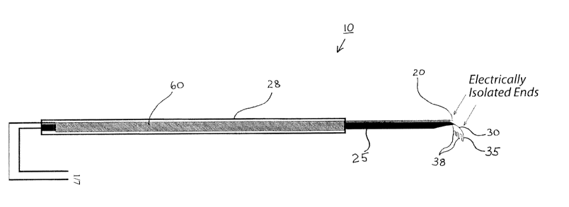
With reference to the attached figures, which show certain embodiments of the
subject invention, it can be seen in Figure 1 that an embodiment of the
subject invention
comprises a retinal rake modified to detect electrical impulses. As mentioned
above, there
are several devices including retinal rakes that can be modified according to
the embodiments
of the subject invention. For example, in one embodiment, a Glaser Flexible
Rake as shown
in Figure 3A can be utilized according to the teachings of the subject
invention.
It can be seen in Figure 3B that a typical retinal rake, like the Glaser
Flexible Rake,
usually removes sections of tissue, such as ERMs, by layers often only a few
cells in
thickness. In this way, the surface of a retina can be cleared of ERM to
provide better light
access to the retina which in many cases can improve vision.
The instruments of the subject invention are particularly useful for surgeries
where
tissue to be removed or destroyed is in close proximity to desired tissue. In
particularly
preferred embodiments, the instruments can be used to remove or destroy
unwanted tissue
that is adjacent to particularly sensitive tissue. Thus, in addition to the
retinal surgery
exemplified herein, the instruments and methods of the subject invention can
be used to
remove tissue that is adjacent to nerves. In specific embodiments, the devices
and methods
of the subject invention can be used to remove tumors and/or herniated disks
that are adjacent
CA 02663291 2009-03-12
WO 2008/033937 PCT/US2007/078290
to nerves, including the spinal cord and associated nerve roots. The devices
and methods can
also be used for delicate brain surgery. In addition to removal of the tissue
from the location
by, for example, cutting or scraping, the removal can also be achieved by
destruction through
physical or chemical means. The physical means can be through, for example,
heat or laser
5 treatment.
Reference herein to "treatment" includes, for example, delivering materials
such as
medicaments to a desired location. The medicaments may be, for example,
therapeutic
compounds (including small organic or inorganic compounds, gene therapies, and
sustained
release formulations) and chemo-or radio-therapeutic compounds that can be
used to, for
example, kill cancer cells. Diagnostic imaging solutions can also be delivered
using the
devices and methods of the subject invention. In one embodiment, the
medicament can be
delivered using a hypodermic needle, or other such device, that is designed as
described
herein such that the person using the device can accurately assess which
tissue the device has
entered.
In one embodiment of the subject invention, a retinal rake is augmented to
include a
signal detector to indicate the type of tissue being removed, touched or
otherwise
manipulated by the rake. To accomplish this, the rake 10 is modified to
include at least two
electrodes. The two electrodes can function as a bipolar pair. In a preferred
embodiment, the
at least two electrodes are electrically isolated. In one embodiment, a first
electrode 20 can
be positioned such that, during a procedure, at least a portion of the first
electrode 20 can be
in continual contact with the vitreous humor of an eye. In one embodiment, the
first
electrode 20 is introduced into the vitreous humor as a component separate
from the rake 10
or other similar device. However, in a more preferred embodiment, the first
electrode 20 can
be affixed to, but electrically isolated from, the rake shank 25. In a still
more preferred
embodiment, the first electrode 20 and the second electrode 35 are affixed
such that the
portion of the second electrode 35 in contact with the vitreous humor is
positioned relatively
close to the rake end 30, for example as shown in Figures 1 and 3B. This
permits the first
electrode 20 to be presented simultaneously with the rake end 30 into an eye.
The second electrode 35 can be positioned at or near the rake end 30, and is
electrically isolated from the first electrode 20. In a further embodiment,
the second
electrode 35 is also electrically isolated from the rake 10 and/or the rake
end 30. However, in
a still further embodiment, the electrically isolated second electrode 35 is
positioned so that
CA 02663291 2009-03-12
WO 2008/033937 PCT/US2007/078290
6
the electrically active (non-electrically isolated) end of the second
electrode 35 is generally
parallel or even with the section of the rake tines 38 that is used to contact
tissue(s). This
allows the second electrode 35 to simultaneously contact the same tissue as
the rake tines 38.
Alternatively, the electrically active end of the second electrode 35 can be
longer or shorter
than the rake tines 38, or contacting end of a similar device.
In yet a further embodiment, the second electrode 35 can be split to comprise
two or
more electrically active contact ends such that two or more areas of the rake
tines 38 can be
monitored. By way of example, each end of a row of rake tines 38 can have a
contact for the
second electrode 35. In a still further embodiment, additional contacts can be
positioned at or
near other sections of the rake tines 38, for further monitoring and feedback
of tissue contact.
In this embodiment, those areas of the rake tines 38 with a second electrode
35 contact can be
monitored with regard to the type of tissue the retinal rake 10 contacts.
Very often optical surgical instruments, including retinal rakes known in the
art,
comprise metallic materials, which are capable of withstanding sterilization
procedures, but
still maintain proper shape and tensile strength. Thus, optical surgical
instruments often
comprise, for example, but are not limited to, titanium, stainless steel,
sterling silver,
aluminum, or combinations thereof. Advantageously, most of the metallic
materials utilized
are able to convey, at least to some degree, an electrical signal.
Therefore, in a preferred embodiment of the subject invention, a retinal rake,
or
similar device, comprises one or more materials able to conduct an electrical
signal. In a
further preferred embodiment, the retinal rake 10, or similar device, of
appropriately
conductive material is augmented to act as the second electrode 35 in the
bipolar pair. In a
yet further preferred embodiment, the retinal rake is almost entirely
insulated such that only a
portion of the rake end 30, at or near the rake tines 38, remains exposed. In
this embodiment,
the retinal rake is protected from random electrical signals from surrounding
tissue, structure
or fluids and is thus able to detect more exact electrical signals from the
tissues, structures,
etc. under direct manipulation or contact during a surgical procedure.
In use, the first electrode 20 and the second electrode 35 are utilized to
detect a
change in electrical impedance created by, and indicative of, contact with
different types
tissues, fluids, or structures. The electrodes are operably connected to
various input
amplification and output electronic components capable of interpreting the
detected
impedance, or lack thereof, and determining from the impedance signal the type
of tissue,
CA 02663291 2009-03-12
WO 2008/033937 PCT/US2007/078290
7
fluid, or structure contacted, and producing one or more appropriate visual,
audio or tactile
signals. Thus, the type of signal generated by the device of the subject
invention can identify
what type of tissue, fluid, or structure has been contacted with the one or
more second
electrodes.
In one embodiment, the retinal rake 10 of the subject invention provides a
visual
signal, such as, for example, one or more lights that may further be of one or
more colors or
shapes. The type of light turned on or off can indicate the tissue type in
contact with the
second electrode 35. In an alternative embodiment, the retinal rake 10 of the
subject
invention provides a tactile signal, such as vibration, heat, cold, pressure,
etc. In this
embodiment, the type of tactile signal can indicate the tissue type in contact
with the second
electrode 35.
In a preferred embodiment, the components of the retinal rake 10 generate one
or
more selectable audio signals, e.g., tones, beeps, whistles, etc. to indentify
the type of
contacted tissue. In a particularly preferred embodiment, the device generates
a certain tone
when the electrodes are not in contact with any tissues, such as when held in
the vitreous
humor, a different tone when the second electrode contacts electrically
inactive tissue or
stn,icture, such ERM, and another tone when the second electrode contacts
electrically active
tissue, such as the retina. Further embodiments, can include additional tones
or sounds to
indicate contact with other structures, such as choroid tissue, schlera, etc.
In an alternative embodiment, the components within the device can also
determine
different levels of signal intensity to indicate proximity to a tissue. For
example, a second
electrode that is in close proximity to a particular tissue, but not in direct
contact with the
tissue may emit the particular tone or sound selected for that particular
tissue, but at a lower
or higher volume, or at increasing or decreasing intermittent beeps, etc. to
indicate a device's
proximity to the tissue. This permits devices to be used as more accurate
probes or indicators
while being used during a surgical procedure.
The signal device used with the subject invention can be positioned in any of
a variety
of locations within appropriate visual, audio, or tactile contact with a
physician. For
example, the signals can be generated by electrical components in operable
contact with the
electrodes, but placed elsewhere in the room (e.g., on a desktop), one or more
other rooms, or
one or more remote locations.
CA 02663291 2009-03-12
WO 2008/033937 PCT/US2007/078290
8
In a preferred embodiment, the retinal rake is modified to include "on-board"
components capable of detecting the various impedance levels, determining the
appropriate
one or more signals for the measured impedance levels, and emitting a signal
indicative of
that impedance level. In a further preferred embodiment, one or more auditory
signals are
generated that correspond to the impedance caused by a tissue, fluid or
structure in contact
with the second electrode. In a still further preferred embodiment, the
retinal rake and the
"on-board" components are self-contained so as to be hand held. In a yet
further preferred
embodiment, the on-board components are contained within a handle 28. In an
alternative
embodiment, the self-contained, hand-held retinal rake 10 further comprises
connecting
components or devices that allow it to be connected to separate devices,
viewing apparatus,
power sources, etc. if necessary or desired.
The components necessary to carry out the subject invention and apply the
novel
principles discussed herein can be accomplished by any of a variety of
different equipment
and devices and can include various modifications, both as to equipment
details and operating
procedures without departing from the scope of the invention itself. While the
invention is
described with reference to specific details of certain circuit embodiments
thereof, it is not
intended that such details be regarded as limiting, except to the extent that
such details are
included in the accompanying claims.
One embodiment of a circuit 60 that can be used in accordance with the
augmented
retinal rake 10 of the subject invention is shown in, for example, the block
diagram of Figure
2. It can be seen in this block diagram example that the processing of the
impedance signal
from the electrodes comprises generally two stages. At stage 1, the circuit
comprises at least
one first electrode 20 and at least one second electrode 35 operably connected
to the circuit
60 through an isolation amplifier 70. The isolation amplifier 70 isolates the
analog
impedance signals from the electrodes, 20 and 35, and sufficiently amplifies
those signals so
that they can be more precisely isolated by other components in the system. In
order to
accurately detect a change in impedance, the circuitry would be preferably
calibrated against
the inherent conductivity of an individual's vitreous humor. Therefore, in a
further
embodiment, the circuit 60 includes an appropriate calibration circuit 71. An
optoisolator 72
can be coupled to the isolation amplifier 7 to isolate the electrode impedance
signal from the
random electrical signals, usually generated by the power source for the
retinal rake 10.
CA 02663291 2009-03-12
WO 2008/033937 PCT/US2007/078290
9
The device of the subject invention can be confrgured to utilize A/C or D/C
current.
As mentioned above, the device is preferably hand-held with the components of
the circuit 60
contained within a handle 28. Therefore, in a preferred embodiment, the device
is operated
on D/C (battery) power, which is also capable of being contained within the
handle 28.
At stage 2 the signal from the optoisolator 72 can be passed through an
amplifier 73
and filter 74 to further isolate the analog impedance signal. The further
isolated signal can be
converted by an analog/digital (AID) converter 75 with the subsequent digital
signal being
processed by a microchip, microcontroller, or Field Programmable Gate Array
(FPGA) chip
76 programmed to analyze the converted digital signal, determine the
appropriate sound or
tone for the level of the input signal received, the input signal being tissue
specific, and
transmit an output signal to a digital amplifier 77 and speaker 78 to generate
an audible tone
or sound selected to be indicative of the particular tissue, fluid, or
structure. The physician
upon hearing the tone or sound can adjust the position of the rake tines 38 to
avoid contact
with retinal tissue.
In alternative embodiments, various components of the retinal rake circuit
described
above can be incorporated into a single chip, or one or more microchips or
FPGAs 76. For
example, the isolation amplifier can be made from a single-package
instrumentation
amplifier, known in the art. Further, utilizing known FPGA technology, a
microcontroller
with onboard A/D and filtering can be used for calibration, filtering and
speaker tone
generation. A person with skill in the art and benefit of the subject
disclosure will be able to
determine various other modifications to these embodiments and such
modification are
contemplated to be within the scope of the subject invention.
All patents, patent applications, provisional applications, and publications
referred to
or cited herein are incorporated by reference in their entirety, including all
figures and tables,
to the extent they are not inconsistent with the explicit teachings of this
specification.
It should be understood that the examples and embodiments described herein are
for
illustrative purposes only and that various modifications or changes in light
thereof will be
suggested to persons skilled in the art and are to be included within the
spirit and purview of
this application.