Note: Descriptions are shown in the official language in which they were submitted.
CA 02663316 2009-03-12
WO 2008/036008 PCT/SE2006/050338
-1-
MULTIPLE RESPONSE OPTIONS FOR
INCOMING COMMUNICATION ATTEMPTS
TECHNICAL FIELD
This invention relates to communication systems. More particularly, and
not by way of limitation, the invention is directed to an arrangement and
method in
a telecommunication network for providing a called party with multiple real-
time
options for responding to incoming communication attempts.
BACKGROUND
Classical telecommunication telephony services enable a called party to
respond to an incoming call by sending a simple busy tone or by referring a
calling
party to another person or to an answering machine. A recent development
enables a called party to send to the calling party, a text message either
predefined or written at the time of the cail attempt. Currently, in Japan,
mobile
users may also respond with melodies, animations, or symbols when they cannot
answer (for example, while commuting in public transportation). Furthermore,
some mobile networks enable a user to predefine a Short Message Service (SMS)
message or a Multimedia Service (MMS) message, which is sent to the calling
party upon reception of an incoming voice call.
The existing solution provides few options in the services it provides to
users, and is cumbersome to implement. Prior to receiving a call, the called
party
can direct the call to a person or a machine. If this has not been done when a
call
is received, the called party can only select to answer or reject the call. If
the
called party rejects the call, the calling party will hear a busy tone and the
call will
be logged as a rejected call. If the called party desires to call back the
calling
party, the called party must access the call list recorded in his mobile phone
and
send a message or make a phone call.
CA 02663316 2009-03-12
WO 2008/036008 PCT/SE2006/050338
-2-
What is needed in the art is an arrangement and method in a
telecommunication network for handling incoming communication attempts that
overcomes the shortcomings of the prior art. Such an arrangement and method
should provide users with the capability to handle incoming communication
attempts in a more flexible and dynamic manner. The present invention provides
such an arrangement and method.
SUMMARY
The present invention provides a called party with multiple options for
dynamically responding to incoming communication attempts. For example, the
called party may reject the call and designate in real time, a personalized
busy
tone, image, music, audio burst, or video burst to be returned to the calling
party.
The called party may also reject the call and refer the calling party to an
ongoing
communication session. The invention provides for the appropriate interactions
between the user and the system, as well as functionality for transporting the
response from the called party to the calling party.
The present invention provides users with richer options for managing
communications, providing both personalization as well as efficiency. For
network
operators, the invention differentiates their services with respect to other
providers, enabling them to attract additional subscribers. Network operators
may
also establish connections with external content providers to obtain content
such
as ring tunes, symbols, or prerecorded audio or video bursts.
Thus, in one aspect, the present invention is directed to an arrangement in
a telecommunication network for providing a called party with multiple real-
time
26 options for responding to an incoming communication attempt from a calling
party.
The arrangement includes a called-party user terminal and network server
means.
The called-party user terminal includes means for notifying the called party
that
the incoming communication attempt has been received, and user terminal client
means. The user terminal client means includes means responsive to receiving
the incoming communication attempt for providing the called party with a
plurality
of response options; means for receiving from the called party, a response
selected from the plurality of response options; and means for communicating
the
CA 02663316 2009-03-12
WO 2008/036008 PCT/SE2006/050338
-3-
selected response to the network. The network server means includes means for
receiving the selected response from the user terminal client means; means for
impiementing the selected response; and means for communicating the selected
response to the calling party.
In another aspect, the present invention is directed to a telecommunication
user terminal for providing a called party with multiple real-time options for
responding to an incoming communication attempt from a calling party. The user
terminal includes means for notifying the called party that the incoming
communication attempt has been received, and user terminal client means. The
user terminal client means includes means responsive to receiving the incoming
communication attempt for providing the called party with a plurality of real-
time
response options; means for receiving from the called party, a response
selected
from the plurality of real-time response options; and means for communicating
the
selected response to the network.
In another aspect, the present invention is directed to an application server
in a telecommunication network for invoking a real-time response selected by a
called party in response to receiving a communication attempt from a calling
party.
The application server includes means for receiving the selected real-time
response from the called party; means for implementing the selected real-time
response; and means for delivering response content to a core network for
delivery to the calling party.
in another aspect, the present invention is directed to a method in a
telecommunication network for providing a called party with multiple real-time
options for responding to an incoming communication attempt from a calling
party.
A called-party user terminal performs the steps of providing the called party
with a
plurality of real-time response options in response to receiving the incoming
communication attempt; receiving from the called party, a response selected
from
the plurality of real-time response options; and communicating the selected
response to the network. The network performs the steps of receiving the
selected response from the user terminal agent; implementing the selected
response; and communicating the selected response to the calling party.
CA 02663316 2009-03-12
WO 2008/036008 PCT/SE2006/050338
-4-
in another aspect, the present invention is directed to a method in a
telecommunication user terminal for providing a called party with multiple
real-time
options for responding to an incoming communication attempt from a calling
party.
The method includes providing the called party with a plurality of real-time
response options in response to receiving the incoming communication attempt;
receiving from the called party, a response selected from the plurality of
real-time
response options; and communicating the selected response to the network.
In another aspect, the present invention is directed to a method in an
application server in a telecommunication network for invoking a real-time
response selected by a called party in response to receiving a communication
attempt from a calling parky. The method includes receiving the selected real-
time
response from the called party; implementing the selected real-time response;
and
delivering response content to a core network for delivery to the calling
party.
In each aspect, the response may be selected from a group of real-time
response options consisting of inviting the calling party to join an ongoing
group
communication session; sending an identified tune to the calling party;
sending an
identified symbol to the calling party; recording and sending a real-time
voice burst
to the calling party; and recording and sending a real-time video burst to the
calling party.
BRIEF DESCRIPTION OF THE SEVERAL VIEWS OF THE DRAWING
In the following, the essential features of the invention will be described in
detail by showing preferred embodiments, with reference to the attached
figures in
which:
FIG. 1 is a simplified block diagram of a network arrangement in which the
present invention has been implemented;
FIG. 2 is a simplified block diagram of a 3GPP wireless network
arrangement in which the present invention has been implemented;
FIGS. 3A-3B are portions of a flow chart illustrating the steps of an
exemplary embodiment of the method of the present invention;
CA 02663316 2009-03-12
WO 2008/036008 PCT/SE2006/050338
_6_
FIGS. 4A-413 are portions of a signaling diagram illustrating the flow of
network messages when configuring the RR service in the network and user
terminals;
FIGS. 5A-5B are portions of a signaling diagram illustrating the flow of
network messages when invoking an RR feature;
FIGS. 6A-6B are portions of a signaling diagram illustrating the flow of
network messages when the called party user rejects a call and selects to send
a
symbol or tune to the calling party user, and SIP transport is utilized;
FIGS. 7A-7B are portions of a signaling diagram illustrating the flow of
network messages when a called party user rejects a call and selects to send a
symbol or tune to the caliing party user, and a SIP message is utilized to
configure
an RTP transport channel;
FIGS. 8A-8B are portions of a signaling diagram illustrating the flow of
network messages when the called party user rejects a call and selects to send
a
symbol or tune to the calling party user, and a predefined RTP channel is
utilized
to deliver the RR content;
FIGS. 9A-9B are portions of a signaling diagram illustrating the flow of
network messages when the called party user rejects a call and selects to send
an
instantly recorded voice, video, or multimedia burst to the calling party
user; and
FIGS. 10A-10B are portions of a signaling diagram illustrating the flow of
network messages when the called party user rejects a call and selects to
invite
the calling party user to join an ongoing group communication session.
DETAILED DESCRIPTION
The present invention, referred to herein as Rich Reaction (RR) call
handling, provides a user several ways of reacting in real time to an incoming
communication request, apart from simply accepting or rejecting the request.
First, the user may reject the request and provide additional information to
the
calling party in a voice or video burst created in real time by the called
party.
Second, the user may reject the request and respond with a tune, symbol, or
another media format provided by a third party. Third, the user may reject the
request and redirect the communication request to another person or device.
CA 02663316 2009-03-12
WO 2008/036008 PCT/SE2006/050338
-6-
Each of the above alternatives is hereafter referred to as "RR features". The
features are applicable to any type of communication between users, not just
duplex voice communications such as a classical telephony call.
FIG. 1 is a simplified block diagram of a network arrangement in which the
present invention has been implemented. The arrangement includes at least two
user equipment (UE) terminals such as UEs 11-13 and an RR network server
(RRS) 14. UE terminal 11 includes an RR client (RRC) 15, and UE terminal 12
includes an RRC 16. All components of the arrangement are interconnected
using a connectivity network 17. The UE terminals and the RRS have
functionality
to support RR features.
A preferred embodiment uses 3GPP IP Multimedia Subsystem (IMS)
technologies, based on the Session Initiation Protocol (SIP). The preferred
embodiment assumes the UEs 11 and 12 are SIP end points, with User Agents
having RR functionality, that is, RRCs. In the network, the RR functionality
is
located in an application in a 3GPP application server in the RRS 14. The RRS
mainly provides services to the user receiving calls (i.e., the called party),
and is
therefore a so-called terminating telecommunications service. The RRS also
provides security services to the caliing party and for an optional third
party such
as a service provider for controlling and managing the RR service.
FIG. 2 is a simplified block diagram of a 3GPP wireless network
arrangement in which the present invention has been implemented. User-A 21 is
a mobile user operating in Network-A 22. User-B 23 is a mobile user operating
in
Network-B 24. Network-A includes a core network having a Serving Call State
Control Function (S-CSCF) 25 and an Interrogating CSCF (I-CSCF) 26, Network-
A also includes a service network 27. Likewise, Network-B includes an I-CSCF
28, an S-CSCF 29, and a service network 30. The typical deployment of the RRS
14 is in the service network, which may be the same network to which the users
are attached (one Network-A and one in Network-B), or in a separate network.
Thus, Network-A is shown to include an application server 14a with an RR
server
application, and Network-B is shown to include an application server 14b with
an
RR server application. RR content servers 31 a and 31 b connected to
application
servers 14a and 14b, respectively, store RR-specific content.
CA 02663316 2009-03-12
WO 2008/036008 PCT/SE2006/050338
-7-
The scenario in FIG. 2 shows User-A 21 placing a call to User-B 23. Using
3GPP IMS and SIP, the preferred embodiment assumes the RRS 14b to be linked
into the chain of entities processing the SIP messages implicitly. That is,
the RRS
14b is not directly addressed by the users or by the RRCs (or any other
entity).
Instead, the RRS is invoked using filters in the S-CSCF 29 via an 1SC
interface.
The filters are configured to trigger on particuCar information in the SIP
requests.
As noted above, the present invention provides the called party with the
capability to respond to incoming calls in different manners, and is thus a
terminating end-user service. In the preferred embodiment, however, the RR
functionality also incorporates security features acting on behalf of the
calling
party. Thus, RR content from a called party is subjected to filtering and
other
security mechanisms before being sent to the calling party. In the preferred
embodiment, this functionality is managed by the network portion of the RR
functionality, more specifically by an RRS.
The preferred embodiment of the RRS 14 assumes a J2EE application
server (with SIP container functionality)-based implementation, or the like,
meaning that a middleware entity intercepts the SIP requests and invokes or
informs the application about certain events as configured. The RRS may get
linked into the chain of SIP entities operating on the S1P dialogue as a proxy
for all
requests from and to a particular user (who has RR) and also subsequent
responses.
In operation, User-A 21 initiates a call attempt to User-B 23. The invitation
includes information about the calling device's ability to support RR
features.
User-B chooses to reject the call and selects an RR type. This may trigger an
indication to User-A that the call is rejected, but User-B is responding with
additional information. User-B enters the content to be sent to User-A. The
particular feature is constructed, and the content is delivered to User-A's
terminal
according to configurations and processing decisions by the RR entities.
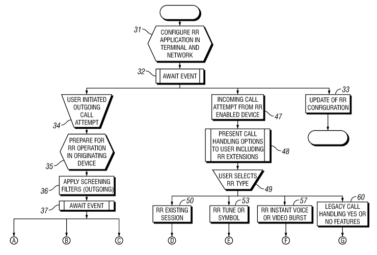
FIGS. 3A-3B are portions of a flow chart illustrating the steps of an
exemplary embodiment of the method of the present invention. At step 31, the
RR application is configured in the RRCs 15 and 16 in the user terminals and
in
the RRS 14. The process then awaits a triggering event at step 32. If the RR
CA 02663316 2009-03-12
WO 2008/036008 PCT/SE2006/050338
-8-
configuration is updated at step 33, the process ends. However, if one of the
users initiates an outgoing call attempt at step 34, the process prepares for
RR
operation in the originating (calling party) device at step 35. At step 36,
the
process applies outgoing screening filters. Filters for outgoing and incoming
RR
messages are available in the RRCs 15 and 16 and in the RRS 14. The RRS and
the RRCs analyze the outgoing message and compare it with a policy that
decides whether the use of RR is possible and allowed. If so, the RRS and RRCs
determine whether there are any restrictions on RR types and implementation
(media type, DRM, size, cost, etc.) that apply for the destination or the
location of
the calling party. The process then awaits a triggering event at step 37.
When a triggering event occurs, there are three possible courses of action,
as shown in FIG. 313, If the called party (peer) accepts the call, the process
moves to step 38 and ends. Alternatively, at step 39, the called party may
reject
the call, but the calling party does not receive an RR indication and the
process
ends. If the called party rejects the call and the calling party terminal
receives an
RR indication, the process moves to step 40. At step 41, the terminal presents
the RR indication to the calling party. The calling party may then activate
the RR
service at step 42 or defer the RR service at step 43. If the RR service is
activated, the process moves to step 44 where the RR content is retrieved, if
necessary, and is presented (audio or visual) to the calling party. If the
calling
party defers the RR service, the process moves to step 45 where the attempt to
establish the call is ended. At step 46, the ongoing RR delivery processes to
deliver the RR content to the calling party are canceled. The RR message
information is stored in the calling party's terminal.
Referring again to FIG. 3A, if the triggering event at step 32 is the receipt
of
an incoming call attempt from an RR-capable device, the process moves to step
47. At step 48, the system presents call handling options to the called party
user
including RR extensions. At step 49, the called party user selects an RR type.
if
the user selects to invite the calling party to join an existing group
communication
session, the process moves to step 50. At step 51 in FIG. 3B, the RRS and RRCs
apply screening filters to the call. For example, the group must be open to
new
participants, and the called party must have permission to invite a new
participant.
CA 02663316 2009-03-12
WO 2008/036008 PCT/SE2006/050338
-9-
In addition, it may be required that the calling party have some necessary
privileges to join the communication. The process then moves to step 52 where
the system delivers and renders the RR type. For example, the system may
coordinate with the core network to obtain the calling party's agreement to
join the
group communication, to join the calling party with the group, and to notify
the
group of the new participant.
Referring again to FIG. 3A, if the user selects at step 49 to play a tune or
send a symbol to the calling party, the process moves to step 53. At step 54
in
FIG. 3B, the RRS and RRCs apply screening filters to the response. At step 55,
the system selects an appropriate media format, size, and transport mechanism
for the user's selected response. At step 56, the system adds the selected
tune or
symbol to the response. The process then moves to step 52 where the system
delivers the tune or symbol to the calling party.
Referring again to FIG. 3A, if the user selects at step 49 to send an instant
voice or video burst to the calling party, the process moves to step 57. At
step 58
in FIG. 3i3, the RRS and RRCs apply screening filters to the response. The RRS
14b retrieves the voice or video burst from the content server 31 b, and at
step 59,
selects an appropriate media format, size, and transport mechanism for the
user's
selected response. The process then moves to step 52 where the system delivers
the instant voice or video burst to the calling party.
Referring again to FIG. 3A, if the called party user selects at step 49 to
exercise one of the traditional (legacy) responses to answer the call (Yes) or
reject
the call (No), the process moves to step 60. The existing legacy process is
then
carried out at step 61 in FIG. 315.
FfGS. 4-10 are signaling diagrams illustrating the flow of network
messages for different RR procedures. All use cases are presented for the case
in which the RRS 14 is implicitly invoked via triggers in the S-CSCF 29. In
other
words, the service network is the same as the network in which the called
party is
registered. The diagrams only illustrate the SIP requests and responses that
are
relevant for the operation of the RR functionality. It should be understood
that
other standard SIP messages are also exchanged between the network entities.
Furthermore, the behavior in the end-user terminals is described at a high
level,
CA 02663316 2009-03-12
WO 2008/036008 PCT/SE2006/050338
-10-
assuming an example realization. A more detailed description of the terminal
realization is given separately.
FIGS. 4A-4B are portions of a signaling diagram illustrating the flow of
network messages when configuring the RR service in the network and user
terminals. In the illustrated case, the calling party user equipment (UE-A) 21
is
located in Network-A 22. The calling party user interfaces with UE-A through a
user interface (Ui) 64. UE-A includes an RR client 65. An IMS/SIP core network
66 connects UE-A to an IMS/SIP core 67 in Network-B 24. The called party user
equipment (UE-B) 23 resides in Network-B and includes an RR client 68 and a
user interface 69. A precondition for service configuration is that the RR
functionality has been installed in the user terminals and in the network.
1MS/SIP
entities including associated databases such as DNS have been configured with
routing information and user service data for authentication and
authorization.
The RRS 14 is started and is waiting for triggering events. The RRS is
configured
with an RRS content server address.
At step 71 in FIG. 4A, the RRS 14 requests the S-CSCF in the IMS/SIP
core network to inform the RRS when specific users register. At step 72, UE-A
is
powered on, and the RR client 65 starts the RR application. At step 73, UE-A
registers in the network by sending a SIP Register message 74 to the iMS/S1P
core network 66. The SIP Register message includes an indication that UE-A is
RR-capable. At step 75, the S-CSCF in the IMS/SIP core network registers UE-A
and informs the RRS that UE-A has registered. The process then moves to FIG.
4B.
At step 76, the RRS 14 triggers authentication and authorization
procedures if they have not been performed by the IMS/SfP core 66. The RRS
stores the RR capabilities of UE-A. The RRS may also download user RR
preferences for filtering incoming RR requests from the database. Finally, the
RRS pushes information to UE-A about pre-created RR content (for example,
symbols and tunes) stored in the network. The information may be provided in
the
form of pointers, URIs, and information about the content such as format,
size,
cost, and the like. At step 77, the RRS 14 sends the information about the
stored
CA 02663316 2009-03-12
WO 2008/036008 PCT/SE2006/050338
-11-
content to the RRC 65 in UE-A. At step 78, the RRC stores the content
information, and at step 79 sends an acknowledgment to the RRS.
FIGS. 5A-5B are portions of a signaling diagram illustrating the flow of
network messages when invoking an RR feature. The following key procedures
are included in the RR preferred embodiment:
= End-user terminals indicate capabilities using media feature tags in the
Accept-Contact header.
= An end-user terminal may support different types of RR, for example a
subset of the features. This is indicated in either the media feature tag or
using
the "a" parameter in the SDP carried in a SIP INViTE message.
= FFS: A special RR ring tone may be generated if the peer device supports
RR. This requires the RRS to keep track of RR capabilities, and requires an
indication of RR ring tone in the SIP 180 message.
= The Reject response includes an RR-type Indication and token identifying
the call attempt.
= A message is sent to the calling party using, for example the SIP REFER
message, to transfer RR content.
Note also the following steps in the sequence in FIGS. 5A-5B:
Step 5: The RRS supporting the calling party, also denoted originating RRS
instance, is linked into the routing of the SIP messages by the S-CSCF based
on
filter criteria set in the S-CSCF. This allows the RRS to create a call state
for the
outgoing request, and optionally validate that the calling party has the right
to
receive RR-content, thus reducing delay.
Step 8: The invitation reaches the RRS acting as a proxy for the called
party. This RRS is also linked into the routing based on filter criteria in
the S-
CSCF in the same network as the called party (i.e. the SIP domain in which he
is
registered). The RRS, also denoted terminating RSS instance, inserts itself in
the
routing for all SIP subsequent responses and requests. This allows for any
third
party to apply local policies in restricting the usage of RR.
Step 18: The called party has selected to reject the calf, but responded with
an RR feature. A reject is sent back to the calling party, using a SIP 380
message. The following RR information is included in the body of the message:
a
CA 02663316 2009-03-12
WO 2008/036008 PCT/SE2006/050338
--12-
token to identify the RR invocation, RR-type, and information about device RR
capability. The SIP 380 message reaches the terminating RRS instance, which
may take different actions (some dependent on the RR-type invoked, as
discussed below), such as authorizing the type of RR invoked by the called
party,
or triggering processes preparing for a possible later RR content delivery to
the
calling party.
Step 21: The reject message with RR-information reaches the originating
RRS instance, which may now apply screening based on content, called party
identity, or other criteria. These criteria may be set either by the User-A or
by a
third party.
Step 24: The indication that the called party, User-B, is responding to the
invitation is delivered to the calling party, User-A. This indication
preferably differs
from the existing reject indication (busy tone) so that the calling party is
made
aware of the difference. The calling party may either wait for the RR
information
from User-B, which should be delivered within 5-10 seconds from the
indication,
or may suppress the RR content being rendered. In the preferred embodiment,
the RR content is delivered to the calling party terminal even if the calling
party
requests suppression.
Step 25 and 26: (This and subsequent steps may run in paralfel with steps
16-24). The called party enters the content to be sent to the calling party,
either
directly by writing a text message or recording a voice burst, video burst, or
the
like, or indirectly by selecting a pre-created content, stored in the network.
The
information is packaged, for example in a SIP MESSAGE or iNFO together with
the same token sent in the reject indication (step 18). The message is tagged
with a media feature tag "RR", which is used to route the message to the RRS
applications.
Step 28: The message arrives at the terminating RSS instance, which
again may take actions depending on the RR type. Also, third-party services
such
as charging, or sending of commercials, may be invoked at this point.
Step 31: The message arrives at the originating RSS instance, which may
apply screening services.
CA 02663316 2009-03-12
WO 2008/036008 PCT/SE2006/050338
-13-
Step 35: The message arrives at the RRC in the calling party device.
Depending on the RR type, the RRC takes different actions, as described below.
The RRC notifies the user about the RR content with a notification, at which
point
the user may select to consume the information. The user may also defer the
information, choosing to view it later. The RRC stores a message in the
terminal
inbox (for example, as an SMS, MMS, or an email) enabling the user to retrieve
the information at a later time.
FIGS. 6A-6B are portions of a signaling diagram illustrating the flow of
network messages when the called party user 23 rejects a call and selects to
send
a symbol or tune to the calling party user 21 using SIP transport. The symbol
or
tune may be provided by the called party user or a third party, and may be
stored
in the network or in the called party terminal (or an associated device such
as a
memory card). The service includes finding and selecting tune(s) or symbol(s)
the
called party user feels fit the purpose for a particular call, constructing a
response,
and delivering the response to the calling party user. When constructing the
service, the RRSs 14a and 14b select the transport method used for carrying
the
burst to the calling party user's terminal based upon the capabilities of the
terminal, the transport prerequisites, and the voice andlor media format. In
exemplary embodiments, a"S1P Message" message or a Real-time Transport
Protocol (RTP) channel is utilized. ln FIGS. 6A-68, SIP transport is utilized.
As preconditions, both user terminals are registered in the IMSISIP core.
Triggers are set in the S-CSCF 29. The RRSs 14a and 14b and the RRCs 65 and
68 are set to manage invocations. Also, it is assumed that the users are
authenticated in the IMS/S1P core.
Note also the following steps in the sequence in FIGS. 6A-6B:
Steps 14-16: The called party rejects the call and selects RR type "tune".
The terminating RRC 68 is invoked and the called party user searches the rich
tunes and selects a tune by identifying a tune ID. The terminating RRC
indicates
this particular RR type in the response to the sender. The terminating RRC
sends
a message carrying information about the identity of the selected tune or
symbol,
for instance in the body of a SIP Message message. If the content is stored
CA 02663316 2009-03-12
WO 2008/036008 PCT/SE2006/050338
-14-
iocally in the called party's terminal, the RRC inserts the tune in the SIP
MESSAGE directly.
Step 17: The terminating RRC 68 creates an RR message body, which is
included in a SIP 380 response message. The RR message body indicates
terminating device RR capabilities, an RR attempt id (token), and the type of
RR
invoked by the called party user (tune).
Step 18: The terminating RRS 14b receives the response message and
verifies the rights of the user to invoke the feature. The terminating RRS
also
finds the tune and analyzes it with respect to the capabilities of the target
terminal
UE-A 21. The appropriate media format and transport method, SIP MESSAGE or
predefined RTP, is used. In the illustrated embodiment, a S1P MESSAGE is used.
The RRS 14ab inserts the tune in the SIP MESSAGE message.
Step 31: The SIP MESSAGE message is intercepted by the originating
RRS 14a, which applies screening filters to the RR type, and then analyzes the
device capabilities and transport preconditions. Based on this information, a
transcoding of the media may be required. Note that this may require the
originating RRS, or rather the owner of it, to have the rights to access the
content,
which may be commercial and therefore encrypted.
FIGS. 7A-7B are portions of a signaling diagram illustrating the flow of
network messages when the cailed party user 23 rejects a call and selects to
send
a symbol or tune to the calling party user 21, and RTP transport is utilized.
In this
embodiment, the RR content is downloaded to the calling party's terminal, UE-
A,
using an RTP channel configured using either a SIP INVITE or REFER message.
The RTP channel may also be pre-configured. The embodiment in FIGS. 7A-7B
assumes the RR content to be stored in the terminating RRS 14b serving the
called party. Thus, the RTP channel and the associated SIP dialogue are
initiated
from the terminating RRS in steps 29 and 38. Alternatively, the content may
originate from the called party's terminal (UE-B), meaning that SIP dialogue
and
RTP transport channels will emanate from UE-B.
The procedure is similar to that of FIGS. 6A-6B until step 26 where the
terminating RRC 68 sends a S1P INVITE or REFER message requesting a UDP
port for an RTP stream along with media configuration information associated
with
CA 02663316 2009-03-12
WO 2008/036008 PCT/SE2006/050338
-15-
the UDP port. The terminating S-CSCF 29 forwards a SIP INVITE message to
Network-A 22 requesting the RTP channel.
Note that the originating RRC 65 automatically accepts the session in step
33. Alternatively, the originating RRC may await the calling party user's
acceptance to view (and/or listen) to the RR message and then accept the
session. If this approach is taken and the calling party user decides not to
consume the RR information immediately, the RR message is deferred, allowing
the calling party user to retrieve it later. The originating RRC stores
information
about the RR message, such as an address for the content (if stored outside
the
terminal), sender, time, and so on. The RRC uses the information to retrieve
the
content if and when the user wishes to read the RR message later.
FIGS. 8A-8B are portions of a signaling diagram illustrating the flow of
network messages when the called party user 23 rejects a call and selects to
send
a symbol or tune to the calling party user 21, and a predefined RTP channel is
utilized to deliver the RR content. In this embodiment, the RRSs and the RRCs
have exchanged information about a UDP port for an RTP stream along with
media configuration information associated with the UDP port. Each such
description of a particular configuration is denoted "predefined RR media
port" in
subsequent discussions. The RRSs may share information about a number of
such predefined RR ports for the RR type "symbol and tunes" as well as for
other
RR types, notably instant voice and video.
The RRS selects the appropriate transport, in this case "predefined RR
media port using RTP." The information about which port was selected is
signaled
in the RR message, carried by SIP message in this example, to the originating
RRS.
FIGS. 9A-9B are portions of a signaling diagram illustrating the flow of
network messages when the called party user 23 rejects a call and selects to
send
an instantly recorded voice, video, or multimedia burst to the calling party
user 21.
In this RR type, the called party user may respond, for example, with an
instantly
recorded voice or video burst, the burst being transferred to the calling
party's
terminal immediately without being stored in the network.
CA 02663316 2009-03-12
WO 2008/036008 PCT/SE2006/050338
--16-
The transport method used for carrying the burst to the calling party
terminal, UE-A, is selected based upon the capabilities of the terminals, the
transport prerequisites, as well as on the format of the voice and/or media
format.
In an example embodiment, SIP MESSAGE message or a predefined RTP
channel is used to deliver the RR content. "Predefined" means that an RRC and
an RRS have exchanged information about RTP ports to use for delivering RR
content.
Note that at step 25 of FIG. 9B, the terminating RRC 68 records a voice
burst as requested by the called party user. The size of the content is kept
small
enough to fit into a SIP MESSAGE message. The terminating RRC then sends a
S(P MESSAGE toward Network-A at step 26 with the recorded RR content and a
token. When the calling party user indicates he is ready to receive the burst,
the
burst is played at step 39.
The voice and video burst may also be transferred to the calling party using
RTP channel(s) estabiished via a SIP INVITE or REFER message, similar to the
method for transferring tunes and symbols illustrated in FIGS. 7A-7B.
FIGS. 10A-10B are portions of a signaling diagram illustrating the flow of
network messages when the called party user 23 rejects a call and selects to
invite the calling party user 21 to join an ongoing group communication
session.
This RR type gives a called party user who is busy communicating in some way
(for example, voice or text chat) the opportunity to invite the calling party
into the
group communication. In this embodiment, the called party chooses a group
among his active groups that he would like the calling party to join. The
calling
party receives an invitation to join a group with a iist of group participants
and the
type of communication media. There may be more than one media type available
in the group. In this case the calling party receives the invitation to join
all media
types and can choose to accept or reject any of the media types.
FIGS. 10A-10B illustrate the scenario in which UE-B is involved in a group
communication using service X (it can be any service) when UE-B receives a
call
from UE-A. UE-B sends an RR-reject upon receiving the incoming call, and sends
a SIP REFER message to UE-A with the address of the group conference server
and the list of participants. If UE-A accepts the invitation, a notification
that UE-A
CA 02663316 2009-03-12
WO 2008/036008 PCT/SE2006/050338
-17-
is joining is sent to all group participants. UE-A then joins the group, and
notification service is set up for UE-A.
Note also the following steps in the sequence in FIGS. 10A-1 QB:
Step 14: At this step, UE-B rejects the call and chooses "Join ongoing
group communication" as the RR-response to UE-A. This step is possible only if
UE-B has permission to invite a new participant to some of the ongoing
communications. it should be noted that this decision may also be based on UE-
A's URi. For example, UE-A may have some necessary privileges to join the
communication.
Step 25: UE-B chooses an ongoing communication from the list on the
terminal. Each ongoing communication may be one of three types:
= Open - UEWB invites UE-A to the ongoing communication;
= Moderated - only the group moderator or the group owner has a
right to add new participants. In this case UE-B makes a request to the
moderator/owner to add UE-A; or
= Closed - UE-B is not allowed to invite any new participant.
It can be recognized from the foregoing description that the present
invention provides many advantages. The users are given richer means to
manage communications, providing for both personalization as well as
efficiency.
Network operators and service providers can use the invention to differentiate
their service offerings in a positive way from those of other providers.
Additionally,
the invention will increase traffic in the operator's network, providing for
additional
revenue-generating events. The invention also provides operators with
increased
opportunities to establish connections with external content providers for RR
content such as ring tunes.
Although preferred embodiments of the present invention have been
illustrated in the accompanying drawings and described in the foregoing
Detailed
Description, it is understood that the invention is not limited to the
embodiments
disclosed, but is capable of numerous rearrangements, modifications, and
substitutions without departing from the scope of the invention. The
specification
contemplates any all modifications that fall within the scope of the invention
defined by the following claims.