Note: Descriptions are shown in the official language in which they were submitted.
WO 2008/033738 CA 02663495 2009-03-13 PCT/US2007/077958
COILED TUBING WELLBORE DRILLING AND SURVEYING USING A
THROUGH THE DRILL BIT APPARATUS
Background of the Invention
Field of the Invention
The invention relates generally to the field of drilling and surveying
wellbores through
Earth formations. More specifically, the invention relates to methods for
drilling and surveying a
wellbore using coiled tubing.
Background Art
U.S. Patent Application Publication No. 2004/0118611 filed by Runia et al.
describes
methods and apparatus for drilling and surveying a wellbore in subsurface
Earth formations in
which a set of survey instruments is placed within a pipe or conduit used to
convey a drill bit into
the wellbore. The set of survey instruments is able to exit the interior of
the pipe or conduit by a
special tool causing a center segment of the drill bit to release, thus
creating an opening for the
survey instruments to leave the pipe or conduit and enter the wellbore below
the bottom of the
pipe or conduit.
The method and apparatus disclosed in the Runia et al. publication is intended
to be used
on so called "jointed" pipe, wherein a length of such pipe is made by
threadedly assembling
segments or "joints" of such pipe into a "string" extended into the wellbore.
It is known in the
art to carry out operations in a wellbore using so-called "coiled tubing." In
coiled tubing
operations, a reel of tubing is transported to the wellbore site. Wellbore
tools of various types,
including drilling tools, are affixed to the end of the coiled tubing, and the
coiled tubing is
unwound from the reel so as to extend into the wellbore. Coiled tubing
wellbore operations have
advantages such as much faster time to exchange wellbore tools by retrieving
the coiled tubing
from the wellbore by spooling the coiled tubing back onto the reel. Such
winding is
considerably faster than uncoupling the threaded connections used with
conventional threadedly
coupled pipe. There is a need to have wellbore drilling and surveying
techniques as disclosed in
the Runia et al. publication that are usable with coiled tubing.
1
CA 02663495 2012-07-03
70677-39
Summary of the Invention
In a method according to one aspect of the invention, a wellbore is
drilled and surveyed using coiled tubing. A method according to this aspect of
the
invention includes unspooling a coiled tubing into a wellbore to a selected
depth
therein. When the tubing is at the selected depth, the tubing is uncoupled and
in
some embodiments a section of coiled tubing containing a latched tool is
inserted into
the coiled tubing. In other embodiments, the tool is inserted into the
uncoupled
tubing. The tubing is reconnected, and the tool is detached from the coiled
tubing
and is moved along the interior of the tubing.
In one embodiment, the tool causes a center drill bit section to become
unlatched from the tubing. The tool is then moved at least in part into the
wellbore
below the portion of the drill bit remaining attached to the coiled tubing
string. The
entire drill bit or drilling assembly may be released in another embodiment.
According to another aspect of the present invention, there is provided
a method for inserting a tool into a wellbore, comprising: extending a coiled
tubing
into the wellbore; at a selected position along the coiled tubing, uncoupling
the coiled
tubing to expose an interior thereof; inserting a tool into the interior of
the coiled
tubing, the tool held in place by a latch; reconnecting the coiled tubing and
releasing
the latch; and operating the tool while moving the coiled tubing through the
wellbore.
According to another aspect of the present invention, there is provided
a method for measuring a wellbore parameter, comprising: inserting a tool
assembly
having at least one sensor therein into the interior of a coiled tubing having
at least
one conduit, wherein the tool assembly is held in place by a latch; extending
the
tubing into a wellbore; and operating the sensor.
According to yet another aspect of the present invention, there is
provided a method for inserting a tool into a wellbore, comprising: extending
a coiled
tubing into the wellbore; at a first selected position along the coiled
tubing, uncoupling
the coiled tubing to expose an interior thereof; inserting the tool into the
interior of the
2
CA 02663495 2012-07-03
70677-39
coiled tubing, the tool held in place by a latch; reconnecting the coiled
tubing; releasing
the latch; and moving the tool along the interior of the tubing to a second
selected
position.
According to another aspect of the present invention, there is provided
a method for operating a tool assembly in a multiple conduit coiled tubing,
comprising:
extending the multiple conduit coiled tubing to a selected depth in a
wellbore; at a first
selected position along the coiled tubing, uncoupling the multiple conduit
coiled tubing
to expose an interior thereof; inserting the tool assembly into a first
conduit of the coiled
tubing, the tool assembly fixed in place at the first selected position by a
latch;
reconnecting the coiled tubing; releasing the latch; and moving the tool
assembly along
the interior of the tubing to a second selected position.
Other aspects and advantages of the invention will be apparent from
the following description and the appended claims.
Brief Description of the Drawings
FIG. 1 is a schematic partially cross-sectional side view of an apparatus
embodying principles of the present invention.
FIG. 1A shows elements of a well pressure control system and coiled
tubing operating devices in more detail.
FIG. 2 is an elevational view of a tubing reel utilized in the apparatus of
FIG. 1.
FIGS. 3-5 are side elevational views of alternate connector systems
utilized in the apparatus of FIG. 1.
FIG. 6 is a quarter-sectional view of a first connector.
FIG. 7 is a quarter-sectional view of a second connector.
2a
CA 02663495 2012-07-03
70677-39
FIG. 8 is an enlarged cross-sectional view of an alternate seal structure
for use with the second connector.
2b
WO 2008/033738 CA 02663495 2009-03-13PCT/US2007/077958
FIG. 9 is a partially cross-sectional view of a sensor apparatus embodying
principles of
the present invention.
FIG. 10 is a schematic partially cross-sectional side view of a variation of
the apparatus
of FIG. 1.
FIG. 10A shows another embodiment of tool assembly in a segment of tubing.
FIG. 11 shows a schematic overview of an embodiment of a through the bit
system.
FIG. 12 shows a schematic drawing of the MWD/LWD survey system of FIG. 11.
FIG. 13 shows a schematic drawing of the drill steering system of FIG. 11.
FIG. 14 shows a schematic drawing of the drill bit of FIG. 11.
FIG. 15 shows a schematic drawing of logging tool that has been passed through
the
bottom hole assembly to extend into the wellbore ahead of the drill string.
FIG. 16 shows a mud motor having a releasable rotor or rotor and stator
combination to
enable movement of wellbore logging instruments below the bottom of the coiled
tubing into the
open wellbore.
FIG. 17 shows one embodiment of an annular mud motor that may be used in
accordance
with the invention.
FIG. 18 shows an alternative embodiment in which wellbore logging sensors
remain
within the tubing string during operation.
FIGS. 19 and 20 show an embodiment of a coaxial, dual coiled tubing.
FIGS. 21 and 22 show embodiments of side by side dual coiled tubing.
FIGS. 23 and 24 show additional embodiments of a side by side coiled tubing.
FIG. 25 shows an example of a tool assembly that can be assembled from a
plurality of
housing segments.
Detailed Description
3
CA 02663495 2011-07-29
74330-36
The principle of inserting various types of wellbore instruments into a coiled
tubing according to the present invention may use, in some embodiments, a
method
and apparatus disclosed in U.S. Pat. No. 6,561,278 to Restarick et al. FIG. 1
shows an apparatus 10 which embodies principles of such apparatus and methods.
In the
following description of the apparatus 10, and with respect to other apparatus
and methods
described herein, directional terms, such as "above", "below", "upper",
"lower", etc., are used
only for convenience in referring to the accompanying drawings and are not
intended to limit the
scope of the invention to any specific relative placement of the various
components described
herein. Additionally, it is to be understood that the various embodiments
described herein may
be used in wellbores having various orientations, such as inclined, inverted,
horizontal, vertical,
etc., and in various configurations, without exceeding the scope of what has
been invented.
In the apparatus 10, a continuous tubing string 12 known in the art is
deployed into a wellbore by
unwinding it from a reel 14. Since the tubing string 12 is initially wrapped
on the reel 14, such
continuous tubing strings are commonly referred to as "coiled tubing" strings.
As used herein,
the term "continuous" means that the tubing string is deployed substantially
continuously into a
wellbore, allowing for some interruptions to interconnect certain tool
assemblies therein, as
opposed to the manner in which segmented or "jointed" tubing is deployed into
a wellbore by
threadedly coupling together individual "joints" or "stands" limited in length
by the height of a
rig supporting structure ("derrick") at the wellbore.
The vast majority of the tubing string 12 consists of tubing 16. The tubing 16
may be
made of a metallic material, such as steel, or it may be made of a nonmetallic
material, such as a
composite material, including, for example, fiber reinforced plastic. As
described below
connectors in the tubing string permit tool assemblies to be inserted into the
interior of the tubing
string 12 for movement to the bottom of the tubing string 12 and/or beyond the
bottom thereof.
In the apparatus 10, wellbore tool assemblies 18 (a packer), 20 (a valve), 22
(a sensor
apparatus), 24 (a wellbore screen) and 26 (a spacer or blast joint) can be
interconnected in the
tubing string 12 without requiring splicing of the tubing 16 at the wellbore,
and without requiring
the tool assemblies to be wrapped on the reel 14. In the present invention,
connectors 28, 30 are
provided in the tubing string 12 above and below, respectively, each of the
tool assemblies 18,
20, 22, 24, 26. These connectors 28, 30 are included into the tubing string 12
prior to, or as, it is
= 4
WO 2008/033738 CA 02663495 2009-03-13PCT/US2007/077958
being wrapped on the reel 14, with each connector's position in the tubing
string 12 on the reel
14 corresponding to a desired location for the respective tool assembly in the
wellbore.
The tool assemblies 18, 20, 22, 24, 26 may also be various forms of wellbore
logging
(formation evaluation) and drilling sensors, including but not limited to
acoustic sensors, natural
or induced gamma radiation sensors, electromagnetic and/or galvanic
resistivity sensors, gamma-
gamma (photon backscatter) density sensors, neutron porosity and/or capture
cross section
sensors, formation fluid testers, mechanical stress sensors, mechanical
properties sensors or any
other type of wellbore logging and formation evaluation sensor known in the
art. Such sensors
may include batteries (not shown) or turbine generators (not shown) for
electrical power.
Signals detected by the various sensors may be stored locally in a suitable
recording medium
(not shown) in each tool assembly, or may be communicated to the Earth's
surface using suitable
telemetry, such as mud pulse telemetry, electromagnetic telemetry, acoustic
telemetry, electrical
telemetry along a cable inside or outside the tubing string 12 or in cases
where the tubing string
12 is made from a composite material having electrical lines therein, as will
be explained in more
detail below, telemetry can be applied to the electrical lines for detection
and decoding at the
Earth's surface. Signals, such as operating commands, or data, may also be
communicated from
the Earth's surface to the tool assemblies in the well using any known type of
telemetry.
The connectors 28, 30 are placed in the tubing string 12 at appropriate
positions, so that
when the tool assemblies 18, 20, 22, 24, 26 are interconnected to the
connectors 28, 30 and the
tubing string 12 is deployed into the wellbore, the tool assemblies 18, 20,
22, 24, 26 will be
disposed at their respective desired locations in the wellbore. In the case of
wellbore logging
sensors, the coiled tubing may be extended into the wellbore and/or retracted
from the wellbore
in order to make a record of the various sensor measurements with respect to
depth in the
wellbore.
The tubing string 12 with the connectors 28, 30 therein is wrapped on the reel
14 prior to
being transported to the wellbore. At the wellbore, the tool assemblies 18,
20, 22, 24, 26 are
interconnected between the connectors 28, 30 as the tubing string 12 is
deployed into the
wellbore from the reel 14. In this manner, the tool assemblies 18, 20, 22, 24,
26 do not have to
be wrapped on the reel 14 or be transported around the gooseneck (G in FIG.
1A).
5
WO 2008/033738 CA 02663495 2009-03-13PCT/US2007/077958
Equipment usually used with coiled tubing in wellbore operations is shown
schematically
in FIG. 1A. The wellbore includes at least a surface casing C cemented
therein. The uppermost
end of the casing C typically will be coupled to a blowout preventer BOP or
similar wellbore
fluid pressure control device. The blowout preventer BOP includes "shear rams"
SR or similar
device capable of closing the wellbore by shearing through the tubing 16 or
other device
disposed within the opening of the blowout preventer BOP. The blowout
preventer BOP may
include an annular pressure control device APC that seals around the exterior
of the tubing 16,
such as one sold under the trademark HYDRIL, which is a registered trademark
of Hydril
Company, Houston, TX. The tubing 16 is moved into and out of the wellbore by
one or more
tubing injectors Ii, 12 of types well known in the art. The tubing injectors
Ii, 12 may have
different diameters if the tubing includes upset diameter elements therein,
such as the connectors
(28, 30 in FIG. 1). The tubing 16 is gradually bent to extend along the
longitudinal axis of the
wellbore by passing over a gooseneck G, which may include a plurality of
rollers R or the like to
enable to tubing 16 to move over the gooseneck G with minimal friction.
Referring to FIG. 2, a view of the reel 14 is shown in which the connectors
28, 30 are
wrapped with the tubing 16 on the reel 14. In the view of FIG. 2 it may be
clearly seen that the
connectors 28, 30 are interconnected to the tubing 16 prior to the tubing 16
being wrapped on the
reel 14. As described above, the connectors 28, 30 are positioned to
correspond to desired
locations of particular tool assemblies in a wellbore Placeholders 38 can be
used to substitute
for the respective tool assemblies between the connectors 28, 30 when the
tubing 16 is wrapped
on the reel 14.
Referring to FIGS. 3-5, various alternate connector systems 32, 34, 36 are
representatively illustrated. In the system 32 depicted in FIG. 3, both of the
connectors 28, 30
are male-threaded, and so a placeholder 40 used to connect the connectors 28,
30 together while
the tubing string 16 is on the reel 14 has opposing female threads. In some
embodiments, a will
be explained in more detail below with reference to FIG. 10A, a segment 159 of
tubing with a
logging tool 160 attached or latched to the inside is inserted into the tubing
string 12 when the
connectors (28, 30 in FIG. 1) are uncoupled. Other embodiments may provide
that the tool
assembly is inserted directly into the interior of the tubing string 12
directly without the need to
an additional segment 159 of tubing. In the system 34 depicted in FIG. 4, the
connector 28 has
6
WO 2008/033738 CA 02663495 2009-03-13 PCT/US2007/077958
male threads, the connector 30 has female threads, and so a placeholder 42 has
both male and
female threads. In the system 36 depicted in FIG. 5, no placeholder is used.
Instead, the male-
threaded connector 28 is directly connected to the female-threaded connector
30 when the tubing
16 is wrapped on the reel 14.
Thus, it may be observed that a variety of methods may be used to provide the
connectors
28, 30 in the tubing string 12. Of course, it is not necessary for the
connectors 28, 30 to be
threaded, or for any particular type of connector to be used. Any connector
may be used in the
apparatus 10, without exceeding the scope of this invention. If the tubing
segment (159 in FIG.
10A), connectors (28, 30 in FIG. 1) and tool assembly 160 introduce an upset
in the tubing
diameter, it may be advantageous to utilize two injector assemblies (IL 12 in
FIG. 1A) or one
injector assembly capable of accommodating tubing with different diameters.
See, for example,
Tubel, U.S. Pat. No. 6,082,454 and/or Rosine, U.S. Pat. No. 6,834,734 to
facilitate movement of
the tubing string 12. It may also be possible to use, as an alternative to the
coupling technique
described with reference to FIG. 1, a fusion bonding method, as practiced by
TubeFuse
Technologies Ltd., Kings Park, Fifth Avenue, Team Valley, Gateshead, Tyne and
Wear, United
Kingdom NE1 1 OAF. Alternatively, the connectors (28, 30 in FIG. 1) may be
made from high
strength material such as titanium or other high strength alloy, such that the
connectors 28, 30
and/or tubing segment (159 in FIG. 10A) do not introduce upsets into the
tubing string 12
diameter. Still another alternative is to join the tubing segments using a so-
called "roll on" or
"crimp on" connector. Such connectors include a profiled insert with external
seals that fits into
the open ends of separated tubing string. A crimping or rolling device then
compresses the
tubing onto the connector to seal the ends and to provide mechanical coupling
between the
tubing ends. One such connector is sold by Schlumberger Technology
Corporation, Sugar Land,
Texas and is identified as a "roll-on" connector.
Referring to FIG. 6, another embodiment of a connector 44 is shown. The
connector 44
may be used in substitution of the connector 28 or 30 in the apparatus 10, or
it may be used in
other apparatus. The connector 44 is configured for use with a composite
tubing 46, which has
one or more lines 48 embedded in a sidewall thereof. A slip, ferrule or
serrated wedge 50, or
multiple ones of these, is used to grip an exterior surface of the tubing 46.
The slip 50 is biased
into gripping engagement with the tubing 46 by tightening a sleeve 58 onto a
housing 60. A seal
7
WO 2008/033738 CA 02663495 2009-03-13 PCT/US2007/077958
52 seals between the exterior surface of the tubing 46 and the sleeve 58.
Another seal 54 seals
between an interior surface of the tubing 46 and the housing 60. A further
seal 62 seals between
the sleeve 58 and the housing 60. In this manner, an end of the tubing 46
extending into the
connector 44 is isolated from exposure to fluids inside and outside the
connector. A barb 56 or
other electrically conductive member is inserted into the end of the tubing
46, 50 that the barb 56
contacts the line 48. A potting compound 72, such as an epoxy, may be used
about the end of the
tubing 46 and the barb 56 to prevent the barb 56 from dislodging from the
tubing 46 and/or to
provide additional sealing for the electrical connection. Another conductor 64
extends from the
barb 56 through the housing 60 to an electrical contact 66. The barb 56,
conductor 64 and contact
66 thus provide a means of transmitting electrical signals and/or power from
the line 48 to the
lower end of the connector 44. Shown in dashed lines in FIG. 6 is a mating
connector or tool
assembly 68, which includes another electrical contact 70 for transmitting the
signals/power
from the contact 66 to the connector or tool assembly 68.
Although the line 48 has been described above as being an electrical line, it
will be readily
appreciated that modifications may be made to the connector 44 to accommodate
other types of
lines. For example, the line 48 could be a fiber optic line, in which case a
fiber optic coupling
may be used in place of the contact 66, or the line 48 could be a hydraulic
line, in which case a
hydraulic coupling may be used in place of the contact 66. In addition, the
line 48 could be used
for various purposes, such as communication, chemical injection, electrical or
hydraulic power,
monitoring of downhole equipment and processes, and a control line for, e.g.,
a safety valve, etc.
Of course, any number of lines 48 may be used with the connector 44, without
exceeding the
scope of what has been invented.
Referring to FIG. 7, an upper connector 74 and a lower connector 76 embodying
principles of the present invention are shown. These connectors 74, 76 may be
used in
substitution of the connectors 28, 30 in the apparatus 10 of FIG. 1, or they
may be used in any
other apparatus.
The connectors 74, 76 are designed for use with a composite tubing 78. The
tubing 78 has
an outer wear layer 80, a layer 82 in which one or more lines 84 is embedded,
a structural layer
86 and an inner flow tube or seal layer 88. This tubing 78 may be a composite
coiled tubing sold
under the trademark FIBERSPAR, which is a registered trademark of Fiberspar
Corporation,
8
WO 2008/033738 CA 02663495 2009-03-13 PCT/US2007/077958
Northwoods Industrial Park West, 12239 FM 529, Houston, Texas 77041. One or
more lines 90
may also be embedded in the seal layer 88.
The wear layer 80 provides abrasion resistance to the tubing 78. The
structural layer 86
provides strength to the tubing 78. The layers 82, 88 isolate the structural
layer 86 from contact
with fluids internal and external to the tubing 78, and provide sealed
pathways for the lines 84,
90 in a sidewall of the tubing 78. Thus, if the lines 84, 90 are electrical
conductors, the layers 82,
88 provide insulation for the lines. Of course, any type of line may be used
for the lines 84, 90,
without exceeding the scope of the invention.
The upper connector 74 includes an outer housing 92, a sleeve 94 threaded into
the
housing 92, a mandrel 96 and an inner seal sleeve 98. The upper connector 74
is sealed to an end
of the tubing 78 extending into the upper connector 74 by means of a seal
assembly 100, which
is compressed between the sleeve 94 and the housing 92, and by means of
sealing material 102
carried externally on the inner seal sleeve 98.
The mandrel 96 grips the structural layer 86 with multiple collets 104, only
one of which
is visible in FIG. 7, having teeth formed on inner surfaces thereof. Multiple
inclined surfaces are
formed externally on each of the collets 104, and these inclined surfaces
cooperate with similar
inclined surfaces formed internally on the housing 92 to bias the collets 104
inward into
engagement with the structural layer 86. A pin 106 prevents relative rotation
between the
mandrel 96 and the tubing 78.
The line 84 extends outward from the layer 82 and into the upper connector 74.
The line
84 passes between the collets 104 and into a passage 108 formed through the
mandrel 96. At a
lower end of the mandrel 96, the line 84 is connected to a line connector 110.
If the line 90 is
provided in the seal layer 88, the line 90 may also extend through the passage
108 in the mandrel
96 to the line connector 110, or to another line connector.
The line connector 110 is depicted as being a pin-type connector, but it may
be a contact,
such as the contact 66 described above, or it may be any other type of
connector. For example, if
the lines 84, 90 are fiber optic or hydraulic lines, then the line connector
110 may be a fiber optic
or hydraulic coupling, respectively.
9
WO 2008/033738 CA 02663495 2009-03-13PCT/US2007/077958
When the connectors 74, 76 are connected to each other, an annular projection
112
formed on a lower end of the inner seal sleeve 98 initially sealingly engages
an annular seal 114
carried on an upper end of an inner sleeve 116 of the lower connector 76.
Further tightening of a
threaded collar 118 between the housing 92 and a housing 120 of the lower
connector 76
eventually brings the line connector 110 into operative engagement with a
mating line connector
122 (shown in FIG. 7 as a socket-type connector) in the lower connector 76,
and then brings an
annular projection 124 into sealing engagement with an annular seal 126
carried on an upper end
of the housing 120. The seals 114, 126 isolate the line connectors 110, 122
(and the interiors of
the connectors 74, 76) from fluid internal and external to the connectors.
Since the lower connector 76 is otherwise similarly configured to the upper
connector 74,
it will not be further described herein. Note that both of the connectors 74,
76 may be connected
to tool assemblies, such as the tool assemblies 18, 20, 22, 24, 26, so that
connections to lines may
be made on either side of each of the tool assemblies. Thus, the lines 84, 90
may extend through
each of the tool assemblies from a connector above the tool assembly to a
connector below the
tool assembly. This functionality is also provided by the connector 44
described above.
Referring to FIG. 8, an alternate seal configuration 128 is representatively
illustrated. The
seal configuration 128 may be used in place of either the projection 112 and
seal 114, or the
projection 124 and seal 126, of the connectors 74, 76.
The seal configuration 128 includes an annular projection 130 and an annular
seal 132.
However, the projection 130 and seal 132 are configured so that the projection
130 contacts
shoulders 134, 136 to either side of the seal 132. This contact prevents
extrusion of the seal 132
due to pressure, and also provides metal-to-metal seals between the projection
130 and the
shoulders 134, 136.
Referring to FIG. 9, an example is shown of a tool assembly 138 which may be
interconnected in a continuous tubing string. The tool assembly 138 is a
sensor apparatus. It
includes sensors 140, 142, 144, 146 interconnected to lines 148, 150 embedded
in a sidewall
material of a tubular body 152 of the tool assembly 138.
The sensors 140, 142, 144, 146 are also embedded in the sidewall material of
the body
152. The sensors 140, 142, 144 sense parameters internal to the body 152, and
the sensor 146
10
WO 2008/033738 CA 02663495 2009-03-13PCT/US2007/077958
senses one or more parameter external to the body 152. Any type of sensor may
be used for any
of the sensors 140, 142, 144, 146. For example, pressure and temperature
sensors may be used.
It would be particularly advantageous to use a combination of types of sensors
for the sensors
140, 142, 144, 146 which would allow computation of values, such as multiple
phase flow rates
through the tool assembly 138.
As another example, it would be advantageous to use a seismic sensor for one
or more of
the sensors 140, 142, 144, 146. This would make available seismic information
previously
unobtainable from the interior of a sidewall of a tubing string.
Note that when using certain types of sensors, the sidewall material is
preferably a
nonmetallic composite material, but other types of materials may be used in
keeping with the
principles of the invention. In particular, the body 152 could be a section of
composite tubing, in
which the sensors 140, 142, 144, 146 have been installed and connected to the
lines 148, 150.
The lines 148, 150 may be any type of line, including electrical, hydraulic,
fiber optic,
etc. Additional lines (not shown in FIG. 9) may extend through or into the
tool assembly 138.
Connectors 154, 156 permit the tool assembly 138 to be conveniently
interconnected in a tubing
string. For example, the connector 76 described above may be used for the
connector 154, and
the connector 74 described above may be used for the connector 156. Via the
connectors 154,
156, the lines 148, 150 are connected to lines extending through tubing or
other tool assemblies
attached to each end of the tool assembly 138.
Referring to FIG. 10, the apparatus 10 is shown wherein a tool assembly 160 is
being
inserted into the interior of the tubing string 12. The tool assembly 160 may
be too long, too
rigid, or too large in diameter to be wrapped on the reel 14 with the tubing
16. In the present
embodiment, the tool assembly 160 may be a set of wellbore logging or
formation evaluation
sensors disposed in a single housing adapted to traverse the interior of the
tubing string 12, and
as will be further explained below with reference to FIGS. 11 through 15, in
some embodiments
may at least partially exit through a special opening in a drill bit disposed
at the end of the tubing
string 12. The sensors measure one or more parameters related to the ambient
environment
inside or outside the tubing string 12, and may include, for example, gamma
radiation, density,
neutron capture cross section, acoustic velocity, pressure, temperature,
electrical resistivity and
11
WO 2008/033738 CA 02663495 2009-03-13PCT/US2007/077958
any other parameter of interest related to the tubing string 12, the wellbore
or the surrounding
subsurface formations.
The connectors 28, 30 are separated, and a placeholder 38 (if used) is removed
prior to
inserting the tool assembly 160 into interior of the tubing string 12. The
tool assembly 160, and
in some embodiments inside tubing segment (159 in FIG. 10A), may be lifted by
a cable
supported by a crane, mast unit or derrick known in the art for supporting
sheave units used with
electrical wireline or slickline deployment systems. The tool assembly 160
inside the tubing
segment (159 in FIG. 10A) in some embodiments is inserted into the tubing
string 12, the lower
connector 30 is reconnected to the upper connector 28, and the tubing string
12 is extended into
the wellbore. As described above, the connectors 28, 30 are provided already
connected to the
tubing 16 when the tubing 16 is wrapped on the reel 14 and transported to the
wellbore. Thus, a
long tool assembly may be inserted into the interior of the tubing string
without the need to wrap
in on the reel 14 or go around the gooseneck (G in FIG. 1A). The tool assembly
160 may
include a latch or similar releasable restraining device (not shown) to hold
the tool assembly 160
in its longitudinal position in the tubing string 12, and in some embodiments
tubing segment 159
inserted into the tubing string 12, until which time it is desired to move the
tool assembly 160
downward in the tubing string 12. Such latch may be released by pumping a
small release tool
or the like through the interior of the tubing string 12, inserted at the
surface end of the tubing
string 12 at the reel 14. Other examples of releasing devices are described
below with reference
to FIG. 10A.
In FIG. 10A, some embodiments of a tool assembly 160 may provide that the tool
assembly 160 is initially disposed in an insertable segment 159 of tubing. The
insertable
segment 159 may include connectors 28A, 30A at its longitudinal ends such that
the segment 159
may be coupled to the tubing string (12 in FIG. 10) substantially as
connecting together the
upper and lower ends of the separated tubing string in other embodiments. The
tool assembly
160 may be coupled to the interior of the segment 159 by one or more types of
latch 161. The
latch 161 in this embodiment and on other embodiments may be operated by any
means known
in the art, including but not limited to, for example, "pigging", fluid
pressure, or electromagnetic
or other signal from outside the tubing string 12.
12
CA 02663495 2011-07-29
74330-36
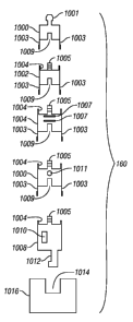
Referring to FIG. 25, in some embodiments, the tool assembly 160 may consist
of a
plurality of housing segments, shown generally at 1000, 1002, 1004, 1006 and
1008 having
longitudinal dimension short enough ancUor being flexible enough to enable
movement of the
segments inside the tubing string (12 in FIG. 10) while it is still on the
reel (14 in FIG. 10). The
housing segments 1000, 1002, 1004, 1006, 1008 may be made from steel, titanium
or other high
strength metal, or from fiber reinforced plastic, for example. The housing
segments, when
moved into contact with each other may make electrical connection between them
using a
submersible electrical connector such as one sold by Kemlon Products and
Development,
Houston, TX. The male portions of such connectors are shown at 1005 at the top
of each of
housing segments 1008, 1006, 1004 and 1002. Female portions of such connectors
are shown at
1009 at the bottom of housing segments 1000, 1002, 1004 and 1006. In the
present embodiment,
the uppermost housing segment 1000, which is the last to be inserted into the
tubing string (12 in
FIG. 1) if inserted by opening the tubing string at or near the Earth's
surface, may include a
power supply and signal processing and storage elements (not shown
separately), and in some
embodiments a gamma radiation sensor or spectral gamma radiation sensor 1010.
The
uppermost housing segment 1000 may also include a fishing neck 1001 at the
upper end thereof
to enable retrieval of all or part of the tool assembly 160 using slickline or
wireline passed
through the tubing string (12 in FIG. 1). The tool assembly 160 may also be
retrieved by reverse
pumping fluid into the bottom of the tubing string (12 in FIG. 1). The housing
segments 1000,
1002, 1004, 1006 may each be coupled to the adjacent, lower housing segment
1002, 104, 1006,
1008 in the tool assembly 160 when contacted with such housing segment by
spring loaded
collets 1003 extending from the bottom of each such housing segment 1000,
1002, 1004, 1006 to
be joined. The upper portion of each housing segment to be joined by the
collets 1003 from the
housing segment above may include an internal groove on an upper shoulder 1018
to receive and
latch the collets 1003.
The second tool housing segment 1002 may include a radiation source, sensors
and
detection circuitry, for example, for a neutron porosity sensing device 1015.
Compensated
neutron devices are described, for example in U.S. Patent No. 4,035,639 issued
to Boutemy et
al.
13
WO 2008/033738 CA 02663495 2009-03-13PCT/US2007/077958
The next housing segment 1004 may include acoustic transducers 1017 for making
various measurements of acoustic properties of the Earth formations penetrated
by the wellbore.
The next housing segment 1006 may include a gamma radiation backscatter
density sensor 1019
that typically includes a gamma radiation source and two spaced apart gamma
radiation
detectors. Some density sensors may also detect photoelectric effect to
provide an indication of
the mineral composition of the Earth formations surrounding the wellbore. The
next housing
segment 1008 may include antennas 1007 and corresponding circuitry (not shown
separately) for
making electromagnetic induction conductivity measurements of the Earth's
formations
surrounding the wellbore. The order in which the segments are assembled as
shown in FIG. 25
is only an illustration of one possible arrangement of sensors and is not a
limit on the scope of
this aspect of the invention.
To deploy such a tool assembly 160 as shown in FIG. 25, the housing segments
1008,
1006, 1004, 1002, 1000 may be inserted into the interior of the tubing string
(12 in FIG. 1) one at
a time at the surface end of the reel (14 in FIG. 1). Fluid may then be pumped
through the
interior of the tubing string (12 in FIG. 1) to move the housing segments
1008, 1006, 1004, 1002,
1000 in the direction of the bottom end of the tubing string (12 in FIG. 1). A
restriction, latch,
muleshoe sub or similar device 1016 may be disposed at a selected position
along the tubing
string (12 in FIG. 1), one such position for example, as explained further
below with reference to
FIG. 18. When the housing segments, starting with segment 1008, reach the
device 1016, a key
1012 on the lower segment 1008 may seat in a corresponding opening 1014 in the
device 1016.
As each successive segment 1006, 1004, 1002, 1000 reaches the upper end of the
succeeding
segment in the tool assembly 160, the collets 1003 will latch in the
corresponding groove 1004 in
the next housing segment. When the last housing segment 1000 reaches the
second housing
segment 1002 the tool assembly 160 will be fully assembled.
As an alternative to using the submersible electrical connectors 1005, 1009
shown in
FIG. 25, only a mechanical connection between segments, such as collets 1003
and grooves
1004, may be used. Sensor and other instrument signals and/or electrical power
may be
transferable between the housing segments using electromagnetic inductive
couplings. See, for
example, Veneruso, U.S. Pat. No. 5,521,592 for one implementation of an
electromagnetic
coupling. The assembled tool assembly 160 may then be operated in its ordinary
manner,
14
CA 02663495 2011-07-29 =
74330-36
including for example, making a record of parameter measurements as the tubing
string (12 in
FIG. 1) is extended further into the wellbore, including during additional
drilling of the wellbore,
and/or as the tubing string (12 in FIG. 1) is withdrawn from the wellbore.
Such operation may
take place entirely within the tubing string (12 in FIG. 1) as well as by
extending the tool
assembly160 part or all the way out of the bottom of the tubing string (12 in
FIG. 1) in a manner
to be further explained below.
The description which follows is related to a method and device shown in
U.S. Patent Application Publication No. 2004/0118611 filed by Runia et al.
Such
method and apparatus as disclosed in the'611 publication is described therein
as
being used in a tubing string that is assembled from threadedly coupled tubing
segments. In the
invention, such method and apparatus has been adapted to be used, in some
embodiments, with a
tool assembly 160 disposed inside a coiled tubing string 12 as set forth
herein, Referring to FIG.
11, the wellbore 1 extends from the Earth's surface into a subsurface Earth
formation 2. The
wellbore 1 is shown as deviated from vertical, wherein the curvature thereof
shown in the FIG.
11 has been exaggerated for the sake of clarity. It is contemplated that the
present invention will
have particular advantages for use in such deviated wellbores, however the
deviation of the
wellbore is not a limit on the scope of the invention.
At least the lower part of the wellbore 1 that is shown in FIG 11 may be
formed by the
operation of certain components coupled to the lower end of the tubing string
12. The
components coupled to the lower end of the tubing string 12 are collectively
referred to as a
"bottom hole assembly" 8, which includes a drill bit 310, a drill steering
system 312 and a
surveying system 315. The bottom hole assembly 8 can include a passage 320
forming part of a
passageway for the tool assembly 160, which may be disposed between a first
position 328 in the
interior of the tubing string 12, above the bottom hole assembly 8, and a
second position 330
inside the wellbore I below the tubing string 12, below the bottom hole
assembly 8 and below
the drill bit 310.
It should be clearly understood that when the lower part of the tool assembly
160 is
disposed below the bottom of the bottom hole assembly 8, the upper part of the
tool assembly
160 can remain in the tubing string 12, for example, hung in or even above the
bottom hole
assembly 8. For purposes of defining this aspect of the present invention it
is sufficient that the
15
WO 2008/033738 CA 02663495 2009-03-13PCT/US2007/077958
lower part of the tool assembly 160 reaches the second position 330 in the
wellbore 1. It should
be noted that various types of sensors may be included in the tool assembly
160 that can be used
to measure one or more parameters in the wellbore 1 as the tool assembly 160
is lowered from
the surface to the first position 328, with measurement data stored in an
internal memory or
storage device in the tool assembly 160 or transmitted to the surface, such as
by mud pressure
modulation telemetry or by electrical and/or optical cable. Examples of
sensors are described
above with reference to FIG. 25. If the tool assembly 160 is positioned or
inserted in the coiled
tubing string (12 in FIG. 1) at the first position 328 when the bottom hole
assembly 8 is at or
near the surface, then the sensors (not shown separately in FIG. 11) can also
make measurements
above the drill bit 310 in logging while drilling ("LWD") fashion as the
wellbore 1 is drilled, in
addition to measuring as described below when the tool assembly 160 is in the
second position
330 as the tubing string 12 and drill bit 310 are withdrawn from the wellbore
1.
In this latter embodiment, with the tool assembly 160 at or near the first
position 328, the
portion of the tubing string 12, or segment (159 in FIG. 10A), adjacent to the
tool assembly 160
can be composed of composite or other electrically non-conductive material to
facilitate making
measurements with sensors adversely affected by steel or other electrically
conductive material.
It is also possible that antenna coils (not shown) can be located in grooves
cut into the outside of
the segment (159 in FIG. 10A) of the tubing string 12 containing the tool
assembly 160, and such
antenna coils (not shown) used to make induction resistivity measurements of
the formations
outside the wellbore 1. Power to the antenna coils and signal received in the
antenna coils can be
communicated across the tubing wall using electrical feed-through bulkheads of
types well
known in the art. Such electrically non-conductive material, whether forming
an entire segment
of the tubing string 12 or whether in the form of "windows" in the tubing
string 12, may also
provide a path for electromagnetic energy if such is used for telemetry of
data from the tool
assembly 160 to the Earth's surface, and/or telemetry from the Earth's surface
to the tool
assembly 160.
In the description which follows, the terms upper and above are used to refer
to a position
or orientation relatively closer to the surface end of the tubing string 12,
and the terms lower and
below for a position relatively closer to the end of the wellbore during
operation. The term
16
WO 2008/033738 CA 02663495 2009-03-13PCT/US2007/077958
longitudinal will be used to refer to a direction or orientation substantially
along the axis of the
tubing string 12.
The drill bit 310 can be provided with a releasably connected insert 335,
which will be
described in more detail with reference to FIG. 14. The insert 335 forms a
selectively removable
closure element for the passageway 320, when it is in its closing position,
i.e. connected to the
drill bit 310 as shown in the FIG. 11.
FIG. 11 further shows a transfer tool 338 which is arranged at the upper end
of the tool
assembly 160, and which serves to deploy the tool assembly 160 from its
insertion point at the
juncture of the connectors (28, 30 in FIG. 2) to the bottom hole assembly 8,
for example, by
pumping. For example, a transfer tool such as disclosed in published British
Patent Application
No. GB 2357787A can be used for such purpose.
Referring to FIG. 12, the surveying system 315 of FIG. 11 is shown in more
detail. The
surveying system of this embodiment can be a measurement/logging while
drilling
("MWD/LWD") system comprising a tubular sub or collar 351 and an elongated
probe 355. The
upper end of the tubular sub 351 is connectable to the upper part of the
tubing string 12
extending to the surface, and the lower end is connectable to the steering
system 312. The probe
355 contains surveying instrumentation, a gamma ray instrument 356, an
orientation tool 357
including e.g. an magnetometer and accelerometer for determining dip and
azimuth of the
wellbore, various logging sensors (such as electromagnetic, acoustic, or
nuclear sensors), a
battery pack 358, and a mud pulser 359 for data communication with the Earth's
surface. The
collar 351 can also contain surveying instrumentation. An annular shoulder 365
is arranged on
the inner circumference of the tubular sub 351, on which the probe can be hung
off The outer
surface of the probe is provided with notches 367 on which keys 369 are
arranged that co-operate
with the annular shoulder 365. The notches 367 allow for fluid to flow through
the MWD/LWD
system, and also induce the mud flow to go through the pulser section 359. The
upper end of the
probe 355 can include a connection means 372 such as a fishing neck or a latch
connector, which
co-operates with a tool such as a wireline tool or a pumping tool that can be
lowered from the
Earth's surface and connected to the connection means 372. The probe 355 can
thus be pulled or
pumped upwardly so as to remove the probe 355 from the collar 351. The MWD/LWD
system
17
WO 2008/033738 CA 02663495 2009-03-13PCT/US2007/077958
has dimensions such that the interior of the collar 351 after removal of the
probe 355 represents a
passageway 320 of suitable size for passage of at least the lower part of the
tool assembly 160.
In other embodiments, a collar-based MWD/LWD system can be used, wherein all
components are arranged around a central longitudinal passageway of required
cross-section, and
do not include the probe 355. In particular, a mud pulser can be provided that
comprises a ring-
shaped rubber member around the passageway, which can be inflated such that
the rubber
member extends into the passageway thereby creating a mud pulse. Other types
of pulsers
include valves that when open divert some of the fluid flow inside the tubing
string into the
annular space between the wellbore and the tubing string, and thus do not
obstruct the central
passageway. Still other MWD/LWD systems include no pulser. Such systems may
include
electromagnetic or acoustic telemetry to communicate data to the Earth's
surface, or may merely
record data in a suitable storage device in the MWD/LWD system itself, for
recovery when the
MWD/LWD system is removed to the Earth's surface.
Referring to FIG. 13, an embodiment of the drill steering system 312 of FIG.
11, in the
form of a mud motor 404 in combination with a bent housing 405 will now be
explained. The
bent housing 405 is shown with an exaggerated bend angle between the upper and
lower ends for
clarity of the illustration. Ordinarily, the bend angle is on the order of
less than three degrees.
The bent housing 405 has an interior comparable to ordinary positive
displacement or turbine-
type drilling motors. The upper end of the mud motor 404 can be directly or
indirectly
connected to the lower end of the surveying system 315.
A mud motor converts hydraulic energy from fluid (drilling mud) pumped from
the Earth's
surface to rotational energy to drive the drill bit (310 in FIG. 11). Such
energy conversion
enables bit rotation without the need for tubing string rotation, and thus is
suitable for drilling
using coiled tubing strings. The mud motor 404 schematically shown in FIG. 13
is a so-called
positive displacement motor ("PDM"), which operates on the Moineau principle.
The Moineau
principle provides that a helically-shaped rotor, shown at 406, with one or
more lobes will rotate
when it is placed inside a helically shaped stator 408 having one more lobe
than the rotor when
fluid is moved through annulus between stator and rotor.
18
WO 2008/033738 CA 02663495 2009-03-13PCT/US2007/077958
Rotation of the rotor 406 is transferred to a tubular bit shaft 410, to the
lower end 412 of
which the drill bit (310 in FIG. 11) can be connected. To transfer the
rotation to the bit shaft
410, the lower end of the rotor 406 is connected via connection means 415 to
one end of a
transfer shaft 418. The transfer shaft 418 extends through the bent housing
405 and is on its
other end connected to the bit shaft via connection means 420. The transfer
shaft 418 can be a
flexible shaft made from a material such as titanium that is able to withstand
the bending and
torsional stresses. Alternatively, the connection means 415 and 420 can be
arranged as universal
joints, constant velocity joints or other flexible coupling. The bit shaft 410
is suspended in a bit
shaft collar 423, which is connected to or integrated with the stator 408,
through bearings 425. A
seal 427 is provided between bit shaft 410 and bit shaft collar 423.
The mud motor steering system of this embodiment differs from known systems in
that
the connection means 420 is arranged to release the connection between the
transfer shaft 418
and the bit shaft 410 when upward force is applied to the rotor 406. For
example, the connection
means can be formed as co-operating splines on the lower end of the transfer
tool and on the
upper part of the bit shaft. A suitable latch mechanism that can be operated
by longitudinal
pulling/pushing is another option. In order to be able to apply upward force
on the rotor 406, the
upper end of the rotor is arranged as a connection means 430 such as a fishing
neck or a latch
connector, which co-operates with a tool that can be lowered from surface,
connected to the
connection means, and pulled or pumped upwardly so as to release the
connection at connection
means 420.
The upper end 432 of the bit shaft 410 is funnel-shaped so as to guide the
lower end of
the transfer tool 418 to the connection means 420 when the rotor 406 is
lowered into the stator
408 again. Fluid passages 435 for drilling fluid can be provided through the
wall of the bit shaft
410, to allow circulation of drilling fluid during drilling operation, when
the rotor 406 is
connected to the bit shaft 410 through connection means 420.
Suitably, there is also arranged a means (not shown) that locks the bit shaft
410 in the bit
shaft collar 423 when the rotor 406 has been disconnected from the bit shaft
410. It shall be clear
that the minimum inner diameter of the stator 408 and the bit shaft 410 are
dimensioned such
that a sufficiently large longitudinal passageway for at least the lower part
of the tool assembly
160 is provided, forming part of the passageway 320 of FIG. 11.
19
WO 2008/033738 CA 02663495 2009-03-13PCT/US2007/077958
An alternative drilling steering system is generally known as rotary steerable
system. A
rotary steerable system generally consists of an outer tubular mandrel having
the outer diameter
of the tubing string. Through the interior of the mandrel runs a piece of
drill pipe of smaller
diameter. The drill string or bottom hole assembly above the rotary steering
system is connected
to the upper end of this inner drill pipe, and the drill bit is connected to
the lower end of the drill
pipe. The mandrel comprises means to exert lateral force on the inner drill
pipe so as to deflect
the drill direction as desired. In order to be used with the present
invention, the inner drill pipe of
the rotary steering system must allow passage of an auxiliary tool. See, for
example, U.S.
Patents Nos. 6,892,830; 6,837,315; 6,595,303; 6,158,529; and 6,116,354 for
various
implementations of rotary steerable directional drilling instruments.
Referring to FIG. 14, a schematically a longitudinal cross-section of an
embodiment of
the rotary drill bit 310 of FIG. 11 is shown. The drill bit 310 is shown in
the wellbore 2, and is
attached in this embodiment to the lower end of the bit shaft 410 of FIG. 13.
The bit body 206 of
the drill bit 410 has a central longitudinal passage 20 for an auxiliary tool
from the interior 207
of the tubing string 12 to the wellbore 1 exterior of the drill bit 310, as
will be explained in more
detail below. Bit nozzles are arranged in the bit body 206. Only one nozzle
with insert 209 is
shown for the sake of clarity. The nozzle 209 is connected to the passageway
20 via the nozzle
channel 209a.
The drill bit 310 is further provided with a removable closure element 435,
which is
shown in FIG. 14 in its closing position with respect to the passageway 420.
The closure element
435 of this example includes a central insert section 212 and a latching
section 214. The insert
section 212 is provided with cutting elements 216 at its front end, wherein
the cutting elements
are arranged so as to form, in the closing position, a joint bit face together
with the cutters 218 at
the front end of the bit body 206. The insert section can also be provided
with nozzles (not
shown). Further, the insert section and the cooperating surface of the bit
body 206 are shaped
suitably so as to allow transmission of drilling torque from the bit shaft
(410 in FIG. 13) and bit
body 206 to the insert section 212.
The latching section 214, which is fixedly attached to the rear end of the
insert section
212, has substantially cylindrical shape and extends into a central
longitudinal bore 220 in the bit
20
WO 2008/033738 CA 02663495 2009-03-13PCT/US2007/077958
body 206 with narrow clearance. The bore 220 forms part of the passage 20, it
also provides
fluid communication to nozzles in the insert section 212.
The closure element 435 is removably attached to the bit body 206 by the
latching section
214. The latching section 214 of the closure element 435 comprises a
substantially cylindrical
outer sleeve 223 which extends with narrow clearance along the bore 220. A
sealing ring 224 is
arranged in a groove around the circumference of the outer sleeve 223, to
prevent fluid
communication along the outer surface of the latching section 214. Connected
to the lower end
of the sleeve 223 is the insert section 212. The latching section 214 further
comprises an inner
sleeve 225, which slidingly fits into the outer sleeve 223. The inner sleeve
225 is biased with its
upper end 226 against an inward shoulder 228 formed by an inward rim 229 near
the upper end
of the sleeve 223. The biasing force is exerted by a partly compressed helical
spring 230, which
pushes the inner sleeve 225 away from the insert section 212. At its lower end
the inner sleeve
225 is provided with an annular recess 232 which is arranged to embrace the
upper part of spring
230.
The outer sleeve 223 is provided with recesses 234 wherein locking balls 235
are
arranged. A locking ball 235 has a larger diameter than the thickness of the
wall of the sleeve
223, and each recess 234 is arranged to hold the respective ball 235 loosely
so that it can move a
limited distance radially in and out of the sleeve 223. Two locking balls 235
are shown in the
drawing, however, more locking balls can be used in other implementations.
In the closed position as shown in FIG. 14 the locking balls 235 are pushed
radially
outwardly by the inner sleeve 225, and register with the annular recess 236
arranged in the bit
body 206 around the bore 220. In this way the closure element 435 is locked to
the drilling bit
410. The inner sleeve 225 is further provided with an annular recess 237,
which is, in the closing
position, longitudinally displaced with respect to the recess 236 in the
direction of the bit shaft
410.
The inward rim 229 is arranged to cooperate with a connection means 239 at the
lower
end of an opening tool 240. The connection means 239 is provided with a number
of legs 250
extending longitudinally downwardly from the circumference of the opening tool
240. For the
sake of clarity only two legs 250 are shown, but it will be clear that more
legs can be arranged.
21
WO 2008/033738 CA 02663495 2009-03-13PCT/US2007/077958
Each leg 250 at its lower end is provided with a dog 251, such that the outer
diameter defined by
the dogs 251 at position 252 exceeds the outer diameter defined by the legs
250 at position 254,
and also exceeds the inner diameter of the rim 229. Further, the inner
diameter of the rim 229 is
preferably larger or about equal to the outer diameter defined by the legs 250
at position 254, and
the inner diameter of the outer sleeve 223 is smaller or approximately equal
to the outer diameter
defined by the dogs 251 at position 252. Further, the legs 250 are arranged so
that they are
inwardly elastically deformable. The outer, lower edges 256 of the dogs 251
and the upper inner
circumference 257 of the rim 229 are beveled.
The outer diameter of the opening tool 240 is significantly smaller than the
diameter of
the bore 220.
Operation of the embodiment of FIGS. 11-14 will now be described. The tubing
string
12 can be used for progressing the wellbore 1 into the formation 2, when the
MWD/LWD probe
355 hangs in the collar 351 as shown in FIG. 12, when the rotor 406 is
arranged in the stator 408
of the mud motor 404 as shown in FIG. 13, and when the insert 435 is latched
to the bit body 206
as shown in FIG. 14. The tool assembly 160 would normally be stored at
surface. The tubing
string 12 can thus be used to drill the wellbore 1 into a desired subsurface
position. The probe
355, the rotor 406 and the insert 435 together form a closure element for the
passageway 20.
In the course of the drilling operation a situation can be encountered, which
requires the
operation of the tool assembly 160 in the wellbore 1 ahead of the drill bit
310. This will be
referred to as a tool operating condition. Examples are the occurrence of mud
losses which
require the injection of fluids such as lost circulation material or cement,
performing a cleaning
operation in the open wellbore, the desire to perform a special logging,
measurement, fluid
sampling or coring operation, the desire to drill a pilot hole.
Drilling is stopped then the tubing string 12 is pulled up a certain distance
to create
sufficient space for at least part of the tool assembly (160 in FIG. 10) at
position 430, and the
passageway is opened. To open the passageway in the present embodiment the
MWD/LWD
probe 355 and the rotor 406 can be retrieved to surface, such as by using a
fishing tool with a
connector means at its lower end that can be pumped down or upwardly through
the drill string
and can also be pulled up again by wireline. Retrieving of the MWD/LWD probe
and the rotor
22
WO 2008/033738 CA 02663495 2009-03-13PCT/US2007/077958
can be done in consecutive steps. The lower end of the probe can also be
arranged so that it can
be connected to the connection means 430 at the upper end of the rotor 406, so
both can be
retrieved at the same time. It will be appreciated by those skilled in the art
that the foregoing
operation may be performed by suitable location of connectors (28, 30 in FIG.
1) in the tubing
string 12, such as explained above with reference to FIG. 10. When a set of
connectors (28, 20
in FIG. 10) is positioned suitably above the top of the wellbore, the
connectors are disconnected,
and a slickline (not shown) or similar device with an appropriate retrieval
latch may be lowered
into the interior of the tubing string 12 to retrieve the probe 355 and rotor
406. After the probe
355 and rotor 406 are retrieved from the bottom hole assembly 8, the tool
assembly 160 may be
inserted into the tubing string 12. In embodiments of a survey system that do
not include the
probe (355 in FIG. 11), it is not necessary to use slickline or the like for
such purpose.
The opening tool 240 can then be deployed, through the interior of the tubing
string 12,
so as to outwardly remove the closure element 435 from bit body 206. The
opening tool 240 is
affixed to the lower end of the tool assembly 160. The tool assembly 160 can
be deployed from
surface by pumping through the interior of the tubing string 12, with the
transfer tool 338
connected to the upper end of the tool assembly 160 (the tool can be logging,
as described above,
as it is lowered to contact the BHA). The tool assembly 160 passes though the
tubing string 12
and the passageway 320 of the bottom hole assembly 8, i.e. consecutively
through the MWD
collar 351 and the stator 408 of the mud motor, until it reaches the upper end
of the drill bit 310,
so that the connection means 239 engages the upper end of the latching section
214 of the
closure element 435. The dogs 251 slide into the upper rim 229 of the outer
sleeve 223. The
legs 250 are deformed inwardly so that the dogs 251 can slide fully into the
upper rim 229 until
they engage the upper end 226 of the inner sleeve 225. By further pushing
down, the inner
sleeve 225 will be forced to slide down inside the outer sleeve 223, further
compressing the
spring 230. When the space between the upper end 226 of the inner sleeve 225
and the shoulder
228 has become large enough to accommodate the length of the dogs 251, the
legs 250 snap
outwardly, thereby latching the opening tool 240 to the closure element 435.
At approximately the same relative position between inner and outer sleeves,
where the
legs snap outwardly, the recesses 237 register with the balls 235, thereby
unlatching the closure
element 435 from the bit body 206. At further pushing down of the opening tool
240 the closure
23
WO 2008/033738 CA 02663495 2009-03-13PCT/US2007/077958
element 435 is integrally pushed out of the bore 220. When the closure element
435 has been
fully pushed out of the bore 220, the passageway 320 is opened.
By moving the opening tool 240 further, the lower part of the tool assembly
160 at the
upper end of the opening tool 240 enters the open wellbore 1 outside of the
drill bit 310, and it
can be operated there. In this embodiment the tool assembly 160 is long enough
so that it
extends through the entire bottom hole assembly 8 and remains connected to the
transfer tool 338
above the bottom hole assembly 8. This allows straightforward retrieval of the
tool assembly
160 to the surface, by slickline, wireline or reverse pumping. The wellbore 1
below the drill bit
310 may be surveyed by moving the entire tubing string 12 along the wellbore
by reeling the reel
(14 in FIG. 1).
FIG. 15 shows the lower end of the drill bit 310 in the situation that a
logging tool 260, of
which the lower part 261 has been passed through the passageway. The closure
element 435 has
been outwardly removed from the closing position by the opening tool 240
disposed at the lower
end of the logging tool 260.
A number of sensors and/or electrodes of the logging tool are shown at 266.
They can be
battery-powered, or can be powered by a turbine or through electrical power
transmitted along a
wireline extending to surface. Data can be stored in the logging tool 260 or
transmitted to
surface. The logging tool 260 further comprises a landing member (not shown)
having a landing
surface, which cooperates with a landing seat of the bottom hole assembly 8.
In one example, the drill bit 310 can for example have an outer diameter of
21.6 cm (8.5
inch), with a passageway of 6.4 cm (2.5 inch). The lower part 261 of the
logging tool, which is
the part that has passed out of the drill string onto the open wellbore, is in
this case substantially
cylindrical and has a relatively uniform outer diameter of 5 cm (2 inch). In
one embodiment, the
portion of the drill bit lowered beneath the tool assembly 160 can be used to
continue to drill a
smaller diameter bore hole for some distance below the bottom of the existing
wellbore, with the
sensors 266 in tool 260 continuing to measure and store and/or transmit
measurement data as the
smaller diameter borehole is being drilled. Drilling power may be provided by
an electrical
connection (not described) to the surface and a downhole electric motor, or by
an additional mud
motor (not shown). When the smaller borehole is drilled to the depth desired,
the same sensors in
24
CA 02663495 2011-07-29
74330-36
the tool assembly 160 can measure, store and/or transmit data as the tubing
string 12 is inserted
into and/or withdrawn from the wellbore.
After the tool assembly 160 has been operated in the wellbore at 430, it can
be retrieved
into the tubing string 12 by pulling up the transfer tool 338. The closure
insert 435 will then
reconnect to the bit body 206. The opening tool 240 will disconnect from the
insert 435, and the
tool assembly 160 can be fully retrieved to the surface. Rotor 406 and MWD/LWD
probe 355
can be lowered into the mud motor and MWD/LWD stator 408, respectively, so
that the closure
element is complete again, and drilling can be resumed. If a following tool
operation condition
occurs, the whole cycle can be repeated, wherein in particular a different
tool assembly can be
used. The flexibility gained in this way during a directional drilling
operation is a particular
advantage of the present embodiment.
An alternative design to the removable center portion of the drill bit as
explained above
with reference to FIGS. 11 through 15 is described in U.S. Patent Application
Publication No.
2005/0029017, by Berkheimer et al., wherein the entire drill bit and/or entire
bottom hole
assembly is released and lowered below the tool assembly.
Yet another alternative embodiment is disclosed in U.S. Patent Application
Publication No. 2006/0118298 filed by Millar et al., which discloses a tubing
string
assembly comprising a tubular first tubing string part with a passageway, and
a second
tubing string part co-operating with the first tubing string part. The
assembly includes a
releasable tubing string interconnecting means for selectively interconnecting
the first and
second tubing string parts. An auxiliary tool is provided for manipulating the
second tubing
string part. The auxiliary tool can pass along the passageway in the first
tubing string part to the
second tubing string part. The assembly further includes a tool-connecting
means for selectively
connecting the auxiliary tool to the second tubing string part, and an
operating means for
operating the tubing string-interconnecting means.
Wardley, U.S. Pat. No. 6,443,247, discloses a casing drilling shoe adapted for
attachment
to a casing string. The shoe comprises an outer drilling section constructed
of a relatively hard
material and an inner section made from a readily drillable material. The shoe
includes means for
controllably displacing the outer drilling section to enable the shoe to be
drilled through using a
= 25
WO 2008/033738 CA 02663495 2009-03-13PCT/US2007/077958
standard drill bit and subsequently penetrated by a reduced diameter casing
string or liner.
Optionally, the outer section may be made of steel and the inner section may
be made of
aluminum. In some embodiments of a system according to the invention, the
drill bit (310 in
FIG. 11) may be substituted by a drilling shoe as disclosed in the Wardley
patent. Such a drilling
shoe in the invention may be rotated by an annular drilling motor, as will be
explained in more
detail below with reference to FIG. 17. Such combination may be in
substitution for all the
components shown in FIGS. 11-15 between the lower end of the tubing string 12
and the drill bit
310. In using components such as shown in the Wardley patent with coiled
tubing according to
the invention, the wellbore is drilled to a selected depth. The tubing string
may be withdrawn a
selected distance out from the well. A tool assembly as explained above with
reference to FIG.
may then be inserted into the tubing string 12. The tool assembly in such
embodiments may
have a device at the bottom end thereof that may open the outer section of the
drilling shoe. The
tool assembly may include a mill, bit or similar device on the bottom thereof
that may be
operated by an electric, hydraulic or drilling fluid-driven motor to rotate
the mill or bit. Thus,
the inner portion of the drilling shoe may be removed, and the tool assembly
may be projected
below the bottom of the tubing string into the wellbore below the bottom end
of the tubing string.
Preferably, the outer section of the Wardley-type drilling shoe is provided
with one or
more blades, wherein the blades are moveable from a first or drilling position
to a second or
displaced position. Preferably, when the blades are in the first or drilling
position they extend in
a lateral or radial direction to such extent as to allow for drilling to be
performed over the full
face of the shoe. This enables the casing shoe to progress beyond the furthest
point previously
attained in a particular well.
The means for displacing the outer drilling section may comprise of a means
for
imparting a downward thrust on the inner section sufficient to cause the inner
section to move in
a down-hole direction relative to the outer drilling section. The means may
include an
obstructing member for obstructing the flow of drilling mud so as to enable
increased pressure to
be obtained above the inner section, the pressure being adapted to impart the
downward thrust.
Typically, the direction of displacement of the outer section has a radial
component.
An alternative embodiment of a mud motor 500 in which all of the internal
components
of the motor may be moved out of the bottom of the coiled tubing string will
now be explained
26
WO 2008/033738 CA 02663495 2009-03-13PCT/US2007/077958
with reference to FIG. 16. The motor includes a housing 500 that is slidably
inserted into the
bottom of the tubing string 12. The bottom of the tubing string 12 may be
particularly formed
for the purpose of mounting the motor, or the motor may be mounted in a drill
collar or similar
device coupled to the lower end of the tubing string 12. The interior of the
tubing string or collar
includes splines or Woodruff keys 506 that mate with corresponding slots in
the exterior surface
of the motor housing 500. The keys or splines 506 rotationally fix the motor
housing 500 with
respect to the tubing string 12, but enable the motor housing 500 to move
axially within the
tubing string 12 or collar. In the present embodiment, the motor housing 500
may be axially
locked within the interior of the tubing string 12 or collar using a locking
device substantially as
explained with reference to FIG. 14, including, for example, an opening tool
240 coupled to the
lower end of the tool assembly (160 in FIG. 10) having dogs 250 or the like at
the lowermost
end. The dogs 250 interact with collets 229 on the upper end of the locking
device to engage the
release tool to the upper end of the motor. Movement of the opening tool 240
to engage the
locking device enables release shaft 225 to move upward under bias from a
spring 230, such that
locking balls 235 are move out of engagement with locking features in the wall
of the tubing
string or collar. Thus, continued movement of the tool assembly 160 downward
will cause the
motor housing 500 to be moved axially out of the bottom of the tubing string
or collar. As the
motor housing 500 is moved outward from the interior of the tubing string or
collar, all the motor
internal active components move therewith, including a rotor 502 having bit
box 504 (and drill
bit 310 coupled therein) coupled thereto, and the stator 508. When the motor
housing is thus
moved out of the bottom of the tubing string or collar, a relatively large
diameter through bore is
created, through which the tool assembly (160 in FIG. 10) may pass into the
wellbore below the
bottom of the tubing string. The embodiment shown in FIG. 16 may be operated
substantially as
explained above with reference to FIGS. 11-15, the difference in the present
embodiment being
that it is not necessary to use slickline or other conveyance to remove the
rotor 502 and other
components (such as the MWD/LWD probe) prior to moving the tool assembly (160
in FIG. 10)
into the wellbore below the bottom of the tubing string or collar.
In other embodiments, the drill bit 310 may be substituted by a roller cone
bit. One of the
cones on the roller cone bit is substituted by a flapper or similar cover
which can be opened to
27
WO 2008/033738 CA 02663495 2009-03-13PCT/US2007/077958
provide passage of the tool assembly 160 below the bit 310, as described in
Estes, U.S. Patent
No. 5,244,050.
Another embodiment of a mud motor having a through passage for the tool
assembly
(160 in FIG. 10) is shown in FIG. 17. The embodiment shown in FIG. 17 can be
referred to as
an annular motor, because the rotating components of the motor are disposed in
an annular space
601 between an interior bore 606 and an outer surface of the motor housing
600. The motor
housing 600 is adapted to be coupled to the lower end of the tubing string 12.
Rotating
components in the present embodiment can include a turbine 602, or may include
positive
displacement ("PDM") components, including but not limited to a Moineau-type
rotor and stator
combination. Rotational output of the turbine 602 or PDM can be coupled to a
bit box 605 of
configurations wellbore known in the art. In the present embodiment, the mud
or other fluid
pumped down the interior of the tubing string 12 has flow indicated by the
arrows in FIG. 17.
The center bore 606 in the operating configuration shown in FIG. 17 includes a
locking plug 604
that may be latched within the internal bore 606 using a latching mechanism
similar to that
shown in and explained with reference to FIG. 14. When the locking plug 604 is
latched in place
in the internal bore 606, fluid flow is diverted to the annular space to drive
the turbine 602 (or
PDM). Fluid can return to the interior bore 606 through ports 608 at the lower
end of the power
section of the motor.
When the user desires to move the tool assembly (160 in FIG. 10) outward
through the
bottom of the tubing string 12 into the open wellbore below, the tool assembly
is moved
downward until the opening tool (240 in FIG. 14) couples with and releases the
locking plug
604. The locking plug 604 then moves downward with the tool assembly (160 in
FIG. 10). The
locking plug 604 in the present embodiment includes releasing features 240A
that are
substantially the same as the opening tool (240 in FIG. 14). Thus, the locking
plug 604 may be
moved to release a center section of the drill bit substantially as explained
with reference to
FIGS. 11 through 15. When such center section is released, the tool assembly
(160 in FIG. 10)
may be moved through the center opening in the drill bit and into the wellbore
below the bottom
of the tubing string 12. Making formation evaluation or similar measurements
using the various
sensors on the tool assembly may be performed substantially as explained above
with reference
28
WO 2008/033738 CA 02663495 2009-03-13PCT/US2007/077958
to FIGS. 11 through 15. Relatching both the center bit section and the locking
plug 604 may be
performed substantially as explained with reference to FIGS. 14 and 15.
Another embodiment is shown in FIG. 18 in which wellbore logging sensors or
similar
apparatus remains inside the tubing string 12 during operation. A sub or
collar 620 is coupled to
the lower end of the tubing string 12. The collar 12 may be made from
composite, electrically
non-conductive material such as glass fiber reinforced plastic, or may be made
from high
strength metal such as titanium. In the case of a metal collar, it may be
useful for certain types of
wellbore logging sensors to include radiation transparent windows 622 located
to be aligned with
the sensor (not shown) on the tool assembly 160. In the present embodiment,
the tool assembly
160 may include an alignment key 626 at its lowermost end, rather than the
opening tool (240 in
FIG. 14) used in other embodiments. When the tool assembly 160 is inserted
into and is moved
through the tubing string 12, the key 626 may seat in a keyway 624 in the
collar 620. The tool
assembly 160 may also be inserted into the collar 620 prior to inserting the
tubing string 12 into
the wellbore. Wellbore logging operations may take place with the tool
assembly 160 seated as
shown in FIG. 18 while the tubing string 12 is moved into and/or out of the
wellbore, while
drilling or otherwise. Information measured by the various sensors (not shown
separately) on the
tool assembly 160 may be recorded in a device in the tool assembly 160, or may
be
communicated by one or more types of telemetry, including fluid pressure
modulation,
electromagnetic radiation, and/or communication along an electrical cable (not
shown). In some
implementations, an antenna in the form of a longitudinally wound coil 628 may
be embedded in
the wall or in a recess in the wall of the collar 620. The antenna 628 may be
used to
communicate signals to and from the tool assembly 160 through a corresponding
antenna 630, or
to communicate signals to and from a different location.
Another embodiment of a coiled tubing string that may be advantageously used
with the
annular motor explained with reference to FIG. 17 will now be explained with
reference to FIGS.
19 and 20. A coaxial, dual coiled tubing 12A is shown being deployed into the
wellbore from a
reel 14 in FIG. 19. The coaxial, dual coiled tubing 12A includes a
substantially open, central
passage or conduit 12C. Coaxially disposed about the central conduit 12C is an
annulus 12B.
The annulus 12B preferably can provide an hydraulic path from the Earth's
surface to the bottom
end of the dual coiled tubing 12A, just as can the central conduit 12C. As
will be appreciated by
29
WO 2008/033738 CA 02663495 2009-03-13PCT/US2007/077958
those skilled in the art, the dual coiled tubing 12A may include one or more
connectors as
explained above with reference to FIGS. 1-10 for insertion of a tool assembly
into the central
conduit 12C. Such tool assembly may be used according to any one or more of
the previously
described embodiments.
In another dual tubing embodiment, a turbine with a central passage to enable
tools to
pass through can be used in the lower portion of the tubing string 12. Such a
turbine is disclosed,
for example, in U.S. Pat. No. 6,527,513 to Van Drentham-Susman et al.
A possible structure for a coaxial, dual coiled tubing 12A is shown in cross
section in
FIG. 20. The tubing 12A includes an outer tube 12E and an inner tube 12D. The
inner tube 12D
defines therein in its interior the central conduit 12C. The inner tube 12D
may be joined to the
outer tube 12D by circumferentially spaced apart supporting ribs 12F. The
supporting ribs 12F
transfer lateral and bending stresses between the inner tube 12D and outer
tube 12E to maintain
the shape and profile of the dual coiled tubing 12A. Interior passages
disposed between the ribs
12F define the passages of the annulus 12B. One or more of the passages may
have therein
disposed electrical lines or cables 13E, or hydraulic lines 14H. Such lines
and cables may be
used in some embodiments to supply power to operate the tool assembly (160 in
FIG. 10) in the
wellbore, and/or to communicate signals from the tool assembly to the Earth's
surface. The
hydraulic lines could also be used to activate mechanical devices in the
bottom hole assembly,
including the latching and unlatching assemblies associated with moving and
positioning the tool
assembly 160 below the drill bit 310, and if desired, retrieval of the tool
assembly 160 and
displaced drill bit 310 back into their ordinary drilling position. In some
embodiments the tool
assembly 160 can be stored in a side pocket while drilling the well and/or
while extending the
tubing string 12 into the wellbore. The hydraulic or electrical power could
also be used in such
circumstances to rotate or otherwise move the tool assembly 160 from the side-
pocket position
into the operating position below the bottom hole assembly as explained with
reference to FIG.
15. It is contemplated that the dual coiled tubing shown in FIG. 19 may be
advantageously used
with the annular motor shown in FIG.. 17, however the annulus 12B when used
with electrical
and/or hydraulic lines may also operate devices such as electric and/or
hydraulic motors to
operate the drill bit (310 in FIG. 14). For embodiments of a dual coiled
tubing made from steel
or similar metal, it is contemplated that the dual coiled tubing 12A may be
made by continuous
30
CA 02663495 2011-07-29
74330-36
extrusion over an extruder die or similar manufacturing technique. It is also
within the scope of
this invention to place one or more sensors (15 in FIG. 19) in selected
positions along the tubing
12A in the annulus 12B. Such sensors may measure fluid pressure, temperature,
signals from the
tool assembly (160 in FIG. 10) and any other parameters that would occur to
those of ordinary
skill in the art. Referring to FIG. 1, in which one of the wellbore tools
disposed in the tubing
string is a packer 18, it is possible using such packer to seal the wellbore
against the exterior of
the tubing string 12 so that selected fluid flow paths with respect to the
tubing 12A can be
isolated. In the example dual coiled tubing of FIG. 19, fluid can be pumped
down the annulus
12B and returned through the central conduit 12C, or vice versa, while the
annular space
between the wellbore and the outer tube 12E remains sealed against fluid flow
by the packer (18
in FIG. 1). Since the central conduit 12C is open from the surface to the
bottom hole assembly,
there being no rotor / stator assembly or other device to impede or block the
passageway, the tool
assembly 160 can be positioned and lowered in the central conduit 12C from the
surface to the
bottom hole assembly, and then further lowered into open borehole below the
bottom hole
assembly as described earlier with reference to FIG. 15. It may be possible,
when the tool
assembly 160 is lowered into such position, for an upper portion of tool
assembly 160 to contain
a transmitter (e.g., electromagnetic or acoustic) that can be aligned with a
corresponding receiver
disposed in the bottom hole assembly. Sensor signals from the various sensors
generated in the
tool assembly 160 can then be transferred from the tool assembly 160 to the
receiver in the
bottom hole assembly, and then further transmitted to the surface by any of
mud pulse telemetry
up the central conduit 12C or annulus 12B, acoustic telemetry up one of the
coaxial coiled
tubular strings, or along an electrical cable in the annulus 12B.
Other embodiments of a non-coaxial dual coiled tubing that may be used in some
embodiments may be similar to a composite coiled tubing such as disclosed in
U.S. Patent No.
5,285,008 to Sas-Jaworsky et al., or U.S. Patent No. 6,663,453 to Quigley.
FIGS. 21 and 22 show embodiments of a dual coiled tubing as in the Sas-
Jaworsky et al. patent.
In FIG. 21 an outer composite cylindrical member 718 is joined to a centrally
located core
member 712 by web members 716 to form two opposing cells 719. The cells 719
are lined with
an abrasive resistant, chemically resistant material 714 and the exterior of
the composite tubular
31
WO 2008/033738 CA 02663495 2009-03-13PCT/US2007/077958
member is protected by an abrasion resistant cover 720. At the center of core
member 712 is an
optional electrical conductor 715 having an insulating sheath 717 surrounding
the conductor 715.
A braided or woven sheath 721 of electrically conductive material is shown
formed about the
insulating sheath 717. The conductor 715 and sheath 721 form an electrical
pair of conductors
for operating tools, instruments, or equipment downhole, which tools are
operably connected to
the composite tubular member.
One advantage of the composite tubular member shown in FIG. 21 is that the
core 712
contains zero-degree oriented fibers which can assume large displacement away
from the center
of the cross-section of the composite tubular member during bending along with
tube flattening
to achieve a minimum energy state. Such deformation state has the beneficial
result of lowering
critical bending strains in the tube. The secondary reduction in strain will
also occur in composite
tubular members containing a larger number of cells, but is most pronounced
for the two cell
configuration.
A variation in design in the two cell configuration is shown in FIG. 22 in
which the zero
degree oriented fiber 722 is widened to provide a plate-like core which
extends out to the outer
cylindrical member 724. In effect, the central core member and the web members
are combined
to form a single web member of uniform cross-section extending through the
axis of the
composite tubular member. Two optional conductors 729 are shown spaced apart
in the material
722 forming a plate-like core.. If mud pulse telemetry or acoustic telemetry
up the tubing string
are used to send data from the tool assembly to the surface, it may be
possible in some
embodiments to place a special fluid either in the annulus of a concentric
dual coiled tubing, or
in one of the isolated dual tubes as shown in FIGS. 21 and 22 to facilitate
mud pulse or acoustic
up-the-pipe telemetry. It is also possible that the side-by-side coiled
tubings as described in
FIGS. 21 and 22 could be made from metallic material housed in a spoolable
outer metallic or
composite sheath.
FIG. 23 illustrates an embodiment of a side by side dual coiled tubing such as
one shown
in U.S. Patent No. 6,663,453 to Quigley, wherein a containment layer 621 of a
continuous
buoyancy control system 620 is discretely attached to the tube 610 through the
use of a plurality
of straps 640. In addition to the illustrated straps 640, other types of
fasteners may also be
employed, including, but not limited to, banding, taping, clamping, discrete
bonding, and other
32
WO 2008/033738 CA 02663495 2009-03-13PCT/US2007/077958
mechanical and/or chemical attachment mechanisms known in the art. The
containment layer
621 of the continuous buoyancy control system 620 may also have a corrugated
outer surface to
inhibit the discrete fastener 640, such as the bands or straps, from
dislodging during the
installation process. For example, the containment layer 621 may have a
corrugated outer surface
having a plurality of alternating peaks and valleys that are oriented
circumferentially, for
example, at approximately 90 degrees relative to the longitudinal axis of the
containment layer
621. The straps 640 may be positioned within the valleys of the corrugated
surface to inhibit
dislodging of the straps 640.
Referring to FIG. 24, the containment layer 621 of the buoyancy control system
620 may
also be continuously affixed to the tube 610 by an outer jacket 650 that
encapsulates the tube 610
and the containment layer 621 of the buoyancy control system 20. In the
illustrated exemplary
embodiment, the outer jacket 650 is a continuous tube having a generally oval
cross-section that
is sized and shaped to accommodate the tube 10 and the buoyancy control system
620. Those
skilled in the art will appreciate that other cross sections, including
circular, may be used and that
the outer jacket 650 may be made in discrete interconnected segments. The
outer jacket 650 may
extend along the entire length of the tube 610 or the buoyancy system 620 or
may be disposed
along discrete segments of the tube 610 and the buoyancy control system 620.
The outer jacket
650 may also be spoolable.
The outer jacket 650 may be a separately constructed tubular or other
structure that is attached to
the tube 610 and the system 620 during installation of the tube 610 and the
system 620.
Alternatively, the outer jacket 650 may be attached during manufacturing of
the tube 610 and/or
the system 620. The outer jacket 650 may be formed by continuous taping,
discrete or
continuous bonding, winding, extrusion, coating processes, and other known
encapsulation
techniques, including processes used to manufacture fiber-reinforced
composites. The outer
jacket 650 may be constructed from polymers, metals, composite materials, and
materials
generally used in the manufacture of polymer, metal, and composite tubing.
Exemplary materials
include thermoplastics, thermoset materials, fiber-reinforced polymers, PE,
PET, urethanes,
elastomers, nylon, polypropylene, and fiberglass
33
WO 2008/033738 CA 02663495 2009-03-13PCT/US2007/077958
Fluid transport, and tool assembly and transport using tubing such as
explained with
reference to FIGS. 21, 22, 23, and 24 may be according to one or more of the
previously
described embodiments for a single coiled tubing or coaxial dual coiled
tubing.
While the invention has been described with respect to a limited number of
embodiments,
those skilled in the art, having benefit of this disclosure, will appreciate
that other embodiments
can be devised which do not depart from the scope of the invention as
disclosed herein.
Accordingly, the scope of the invention should be limited only by the attached
claims.
34