Note: Descriptions are shown in the official language in which they were submitted.
CA 02663606 2009-04-22
COOKING APPLIANCE
SUMMARY
The present disclosure is directed to a cooking appliance, and more
particularly to
a cooking appliance for producing flatbreads or other foodstuffs.
In an embodiment, a cooking appliance is provided. The cooking appliance
includes a first cooking surface and a second cooking surface. The second
cooking
surface is operatively connected to the first cooking surface. The first
cooking surface is
locatable in at least three operative positions relative to the second cooking
surface.
In another embodiment, a cooking appliance is provided. The cooking appliance
includes a first cooking surface and a second cooking surface. The second
cooking
surface is translatable in a substantially linear manner relative to the first
cooking surface.
In another embodiment, a cooking appliance is provided. The cooking appliance
includes a base and a lower heating assembly connected to the base. The lower
heating
assembly includes a substantially flat lower cooking surface. The cooking
appliance
further includes an upper heating assembly that is operatively connected to
the lower
heating assembly. The upper heating assembly includes an upper cooking
surface,
wherein the upper cooking surface has a spiral-shaped raised pattern.
In another embodiment, the cooking appliance includes a lower heating assembly
and an upper heating assembly. The lower heating assembly includes a
substantially flat
lower cooking surface and both a resting aperture and a receiving aperture.
The cooking
appliance further includes an upper heating assembly that is operatively
connected to the
lower heating assembly. The upper heating assembly includes an upper cooking
surface,
wherein the upper cooking surface has a spiral-shaped raised pattern. The
upper heating
assembly further includes a guide post extending from the upper heating
assembly. In
this embodiment, the cooking appliance is configured such that when the
cooking
appliance is in a first operative position, the guide post rests in the
resting aperture and
when the cooking appliance is in a second operative position, the guide post
extends into
the receiving aperture. In this embodiment, the guide post ensures that the
upper heating
assembly moves in a substantially linear manner relative to the lower heating
assembly.
Or in other words, such that the upper heating assembly is substantially
parallel to the
1
CA 02663606 2009-04-22
lower heating assembly as it translates relative to the lower heating
assembly. In one
embodiment, the upper heating assembly and lower heating assembly include
respective
male and female stabilizing members. In another embodiment the lower heating
assembly includes an overflow reservoir located radially outward from the
lower cooking
surface.
In other embodiments, a cooking appliance is provided which includes an upper
and lower heating assembly, each including multiple respective upper and lower
cooking
surfaces. Such a cooking appliance enables the simultaneous cooking of
multiple food
items.
Advantages of the present invention will become more apparent to those skilled
in
the art from the following description of the preferred embodiments of the
invention
which have been shown and described by way of illustration. As will be
realized, the
invention is capable of other and different embodiments, and its details are
capable of
modification in various respects. Accordingly, the drawings and description
are to be
regarded as illustrative in nature and not as restrictive.
BRIEF DESCRIPTION OF THE FIGURES
FIG. 1 is a top perspective view of an embodiment of a cooking appliance in
accordance with the present disclosure;
FIG. 2 is a top perspective view of an embodiment of a base;
FIG. 3 is a side view of the base of FIG. 2;
FIG. 4 is a front view of the base of FIG. 2;
FIG. 5 is a top perspective view of an embodiment of a lower heating assembly;
FIG. 6 is a cross-sectional view of the lower heating assembly along line VI-
VI of
FIG. 5;
FIG. 6A is a cross-sectional view of another embodiment of a lower heating
assembly;
FIG. 7 is a top perspective view of an embodiment of an upper heating
assembly;
FIG. 8 is a cross-sectional view of the upper heating assembly along line VIII-
VIII of FIG. 7;
FIG. 9 is a bottom view of the upper heating assembly of FIG. 7;
2
CA 02663606 2009-04-22
FIG. 10A is a side view of an embodiment of a cooking appliance in a first
operative position;
FIG. 10B is a top perspective view of the cooking appliance of FIG. 10A in the
first operative position;
FIG. 11A is a side view of an embodiment of a cooking appliance in a second
operative position;
FIG. 11B is a top perspective view of the cooking appliance of FIG. 11A in the
second operative position;
FIG. 12A is a side view of an embodiment of a cooking appliance in a third
operative position;
FIG. 12B is a top perspective view of the cooking appliance of FIG. 12A in the
third operative position;
FIG. 13A is a side view of an embodiment of a cooking appliance in a fourth
operative position;
FIG. 13B is a top perspective view of the cooking appliance of FIG. 13A in the
fourth operative position;
FIG. 14 is a perspective view of one embodiment of the cooking appliance in a
first operative position;
FIG. 15 is a perspective view of the lower heating assembly of one embodiment
of the cooking appliance;
FIG. 16A is an exploded perspective view of a hinge assembly included in one
embodiment of the cooking appliance;
FIG. 16B is a perspective view of part of a hinge assembly included in one
embodiment of the cooking appliance;
FIG. 17 is a perspective view of the upper heating assembly of one embodiment
of the cooking appliance;
FIG. 18 is a perspective view of one embodiment of a cooking appliance
including a plurality of respective upper and lower cooking surfaces;
FIG. 19 is another perspective view of one embodiment of a cooking appliance
including a plurality of respective upper and lower cooking surfaces;
FIG. 20 is a side view of one configuration of a lower cooking plate;
3
CA 02663606 2009-04-22
FIG. 21 is a perspective view of an embodiment of the upper and lower heating
assemblies of the cooking appliance;
FIG. 22 is a perspective view of an embodiment of the upper and lower heating
assemblies of the cooking appliance; and
FIG. 23 is an illustration of a variety of possible elements which may be
included
in a pattern on an upper or lower cooking plate.
DETAILED DESCRIPTION
Referring to FIG. 1, an embodiment of a cooking appliance 10 is shown. The
cooking appliance 10 may be configured to produce any foodstuff including, but
not
limited to, flatbreads, tortillas, crepes, pitas, paninis, pancakes, naan,
pizzelles,
knaeckebrot, krumkakes, dosas, hamburgers, hotdogs, quesadillas, brats, or any
other
food. In the description below, it should be understood that the term
"foodstuff' is used
for ease of description in a broad sense and in a non-limiting way to include
any foodstuff
or food item that may be produced using either a single heated surface or a
pair of
opposing heated surfaces.
In an embodiment, a cooking appliance 10 includes a base 12, a lower heating
assembly 14, and an upper heating assembly 16, as illustrated in FIG. 1. The
base 12
provides a solid foundation for the cooking appliance 10, thereby allowing the
cooking
appliance 10 to be placed on a countertop, tabletop, or any other sufficiently
flat and
sturdy surface. The base 12 is adapted to provide structural support for the
lower heating
assembly 14 and the upper heating assembly 16. The base 12 may be formed of
plastic,
metal, metal in which at least a portion is overmolded with plastic, or any
other material
sufficient to support the lower and upper heating assemblies 14, 16 as well as
provide
heat insulation to prevent the user from being burned if the base 12 is
touched during
operation. In another embodiment, the base 12 may include rubber or plastic
feet (not
shown) extending downward from the bottom of the base 12, wherein the feet are
adapted
to provide a cushion between the base 12 and the surface upon which the
cooking
appliance 10 is located. The feet may also provide a frictional connection
between the
cooking appliance 10 and the surface against which the base 12 abuts in order
to prevent
the cooking appliance 10 from sliding relative to the surface. The feet may be
formed of
plastic, rubber, or any other material sufficient to provide a cushioned
spacer and prevent
4
CA 02663606 2009-04-22
the base 12 from sliding relative to the surface upon which the cooking
appliance 10 is
placed.
In an embodiment, the base 12 is a generally elongated member, as shown in
FIGS. 2-5, and includes a front portion 18, a central portion 20, and a rear
portion 22. In
use, the cooking appliance 10 is generally aligned such that the user faces
the front
portion 18 of the base 12. The front portion 18 includes controls and
indicators, as
illustrated in FIG. 4. The front portion 18 includes a temperature control 24,
a
temperature indicator 26, and a timer control 28. The temperature control 24
allows a
user to selectively adjust the temperature of the lower heating assembly 14
and the upper
heating assembly 16 either concurrently or individually. The temperature
control 24 may
allow the user to select an actual temperature or a relative temperature of
the lower and
upper heating assemblies 14, 16.
In an embodiment, the temperature control 24 includes a sliding mechanism 30
configured to allow the user to selectively increase or decrease the relative
temperature of
the lower and/or upper heating assemblies 14, 16 of the cooking appliance 10,
as
illustrated in FIG. 4. The sliding mechanism 30 has a range of movement that
corresponds to the upper and lower adjustable temperature range of the lower
and upper
heating assemblies 14, 16. When the sliding mechanism 30 is placed at one
limit, the
heating assemblies 14, 16 are at the lowest selectable temperature limit. When
the sliding
mechanism 30 is at the opposite limit, the heating assemblies 14, 16 are at
the highest
selectable temperature limit. In an embodiment, a single sliding mechanism 30
concurrently controls the temperature of both the lower and upper heating
assemblies 14,
16. In another embodiment, the front portion 18 may include a second sliding
mechanism (not shown) such that one sliding mechanism is configured to
selectively
adjust the temperature of the upper heating assembly 16 and the other sliding
mechanism
is configured to selectively adjust the temperature of the lower heating
assembly 14. The
sliding mechanism 30 is configured to slide in a substantially horizontal
manner, but it
should be understood by one skilled in the art that the sliding mechanism 30
may be
aligned to slide in a vertical manner or to rotate. The sliding mechanism 30
allows the
user to selectively adjust the temperature of the lower and upper heating
assemblies 14,
16 in which each position along the sliding mechanism corresponds to an actual
temperature within an adjustable temperature range of the cooking appliance
10.
5
CA 02663606 2015-11-05
The temperature control 24 may also allow the user to selectively adjust the
actual
temperature of the lower and upper heating assemblies 14, 16. In an
embodiment, the
temperature control 24 is a rotatable knob (not shown) in which the knob
includes indicia on
the front portion 18 of the base 12 that correlates to the actual temperature
of the heating
assemblies 14, 16. In another embodiment, the temperature control 24 is a
switch (not shown)
having a plurality of selectable positions wherein each selectable position
corresponds to an
actual temperature of the heating assemblies 14, 16. In another embodiment,
the temperature
control 24 is a digital interface (not shown), wherein the user may select a
specific temperature
of the heating assemblies 14, 16. It should be understood by one skilled in
the art that the
temperature control 24 may be any mechanism sufficient to allow the user to
selectively
increase or decrease the actual or relative temperature of the lower and/or
upper heating
assemblies 14, 16. In another embodiment, the front portion 18 may also
include a temperature
display (not shown) that provides the actual measured temperature of the lower
and upper
heating assemblies 14, 16. Such a temperature display may be separate from, or
integrated
with, the temperature control 24.
The front portion 18 of the base 12 further includes a temperature indicator
26, as
shown in FIG. 2. In an embodiment, the temperature indicator 26 includes a red
LED (light
emitting diode) 32 and a green LED 34, as shown in FIG. 4. The red LED 32 and
the green
LED 34 are connected to a temperature control circuit (not shown). The
temperature control
circuit receives a signal from the temperature control 24 indicating the
temperature selected by
the user and a signal representing the temperature of the lower and upper
heating assemblies
14, 16. The temperature control circuit also includes a comparator that
determines if the
measured temperature of the lower and upper heating assemblies is above, below
or equal to
the temperature selected by the user. When the cooking appliance 10 is plugged
into an outlet,
the red LED 32 remains lit. If the measured temperature is equal to or above
the temperature
selected by the user, the temperature control circuit provides an output
signal to illuminate the
green LED 34 in addition to the red LED 32 which remains illuminated, thereby
indicating that
the cooking appliance 10 is heated to the selected temperature and ready for
use.
In another embodiment, the temperature indicator 26 is a single LED that
indicates
when the lower and upper heating assemblies 14, 16 have reached the user-
6
CA 02663606 2009-04-22
selected temperature. In an embodiment, the single LED may receive an output
signal
from the temperature control circuit to illuminate the single LED only when
the measured
temperature is below the temperature selected by the user. In the alternative,
the single
LED may receive an output signal from the temperature control circuit to
illuminate the
single LED only when the measured temperature is equal to or above the
temperature
selected by the user. In another embodiment, the temperature indicator 26 may
produce
an audible sound to indicate when the measured temperature is equal to the
temperature
selected by the user to indicate that the lower and upper heating assemblies
14, 16 have
been sufficiently preheated. It should be understood by one skilled in the art
that the
temperature indicator 26 may provide visual or audible indicators either alone
or in
combination to indicate various temperatures, including but not limited to the
temperature
selected by the user, of the lower and upper heating assemblies 14, 16. It
should be
appreciated that although the above temperature indicators include LEDs, the
indicators
may include any type of light or illuminating device. Also, it should be
appreciated that
in other embodiments of the cooking appliance 10, the cooking appliance 10
does not
include at least one of temperature controls and temperature indicators.
In an embodiment, the front portion 18 of the base 12 includes a timer control
28,
as illustrated in FIG. 2. The timer control 28 may include a rotatable knob
36, as shown
in FIG. 4, which provides a timer for the cooking appliance 10. The knob 36 is
operatively connected to a bell (not shown), or other audible source, located
on the rear
surface of the front portion 18. The knob 36 is rotatable between a stop
position and a
timing position. The timer control 28 can be controlled by a knob or any other
mechanical or electrical timing means known in the art. It should be
appreciated that in
other embodiments of the cooking appliance 10, the cooking appliance 10 does
not
include a timer.
The front portion 18 of the base 12 also includes a lower latch member 38
attached thereto, as shown in FIGS 2 and 3. The lower latch member 38 includes
a
securing member 39 and a stabilizing member 40. The lower latch member 38
extends
upwardly from the base 12. The lower latch member 38 is configured to engage
the
upper heating assembly 16, as will be discussed below.
The central portion 20 of the base 12 includes a recessed region 41 adapted to
receive the lower heating assembly 14, as shown in FIG. 3. The recessed region
41 is
7
CA 02663606 2009-04-22
formed as substantially the same shape as the bottom surface of the lower
heating
assembly 14 such that the lower heating assembly 14 can fit within the
recessed region
41. The recessed region 41 also includes a plurality of bosses 42 (FIG. 2)
that are
adapted to allow the lower heating assembly 14 to be attached to the base 12.
The rear portion 22 of the base 12 includes a receiving region 44 adapted to
receive the rear portions of the lower and upper heating assemblies 14, 16, as
shown in
FIG. 2. The receiving region 44 includes a pair of lugs 46 located on the
inner surface of
the receiving region 44. The lugs 46 are adapted to receive and support the
hinge
mechanism between the lower and upper heating assemblies 14, 16. The receiving
region
44 further includes a pair of curved surfaces, or stop members 48, configured
to
selectively position the upper heating assembly 16 when in operation or
otherwise. The
rear portion 22 of the base 12 includes a substantially flat rear surface that
allows the
entire cooking appliance 10 to be stored in an upright position on the flat
rear surface of
the base 12.
Referring to FIGS. 5 and 6, the lower heating assembly 14 of the cooking
appliance 10 is shown. In an embodiment, the lower heating assembly 14
includes a
lower cover 50, lower heating member 52, lower insulator 54, lower thermostat
assembly
56, and a hinge guide 58. The lower cover 50 is adapted to be received in the
recessed
region 41 of the base 12. The lower cover 50 may be formed of injection molded
plastic,
compression molded plastic, metal, ceramic, or any other material sufficient
to provide
protection to the lower heating member 52 of the lower heating assembly 14. In
an
embodiment, the lower cover 50 is formed of stainless steel. The lower cover
50 includes
a plurality of apertures 60 formed therethrough. The apertures 60 formed in
the
upwardly-curved surfaces of the lower cover 50 are adapted to receive a
connecting
mechanism (not shown) for connecting the lower cover 50 to the lower heating
member
52 and the lower insulator 54. The lower cover 50 includes a cut-out 62 that
is adapted to
receive the lower thermostat assembly 56 that extends upwardly from the lower
cover 50
to the lower heating member 52. The lower cover 50 is formed as an upwardly-
directed
bowl-shaped member. In an embodiment, the lower cover 50 has a round shape,
but it
should be understood by one skilled in the art that the lower cover 50 can
have any shape
sufficient to be received in the recessed region 41. The shape of the lower
cover 50 is
8
CA 02663606 2009-04-22
sufficiently similar to the lower heating member 52 such that the lower cover
50 covers a
substantial portion of the downwardly-directed surface of the lower heating
member 52.
The lower heating assembly 14 includes a lower insulator 54 disposed between
the lower cover 50 and the lower heating member 52, as illustrated in FIG. 6.
A lower
heating element (not shown) is disposed adjacent to the lower heating member
52
between the lower insulator 54 and the lower heating member 52. The lower
heating
element is controlled by the lower thermostat assembly 56. The lower insulator
54 may
be formed of ceramic, fiberglass, mineral fabric, or non-asbestos insulation.
In an
embodiment, the lower insulator 54 is formed of glass reinforced plastic. It
should be
understood by one skilled in the art that the lower insulator 54 may be formed
of any
material sufficient to insulate the lower cover 50 from the lower heating
member 52 to
prevent the lower cover 50 from deforming as a result of the heat from the
lower heating
member 52. In an embodiment, the lower insulator 54 is located in a spaced-
apart
relationship relative to the bottom surface of the lower heating member 52 and
the upper
surface of the lower cover 50 to provide a gap therebetween. In an embodiment,
the
outer edge of the lower insulator 54 is spaced apart from the upwardly-
directed surface of
the lower cover 50. In another embodiment, the outer edge of the lower
insulator 54 is in
an abutting relationship with the upwardly-directed surface of the lower cover
50.
In an embodiment, the lower heating member 52 includes a lower cooking plate
64 and the hinge guide 58 that are formed as a unitary member, as illustrated
in FIGS. 5
and 6. In another embodiment, the lower cooking plate 64 and the hinge guide
58 are
formed as separate members that are thereafter connected to each other in a
substantially
rigid manner. In another embodiment, the lower cooking plate 64 and the hinge
guide 58
are formed as separate members that are thereafter releasably connected to
each other,
thereby allowing the lower cooking plate 64 to be removed from the hinge guide
58 for
disassembly. The lower heating assembly 14 is adapted to receive the lower
thermostat
assembly 56, and the lower thermostat assembly 56 is configured to control the
cooking
temperature of the lower cooking plate 64. In an embodiment, the lower cooking
plate 64
is a substantially circular member with a radius of between about eight (8)
inches to
fourteen (14) inches (20.3 to 35.6 cm). It should be understood by one skilled
in the art
that the lower cooking plate 64 may be round, square, triangular, rectangular,
oval, or any
other shape sufficient to provide a heated cooking surface. The lower cooking
plate 64
9
CA 02663606 2009-04-22
may be made of a substantially non-stick material, or the lower cooking plate
64 may
include a non-stick surface added to its surface.
In an embodiment, the lower heating member 52 includes a raised edge 66 that
is
spaced radially inward from the outer edge of the lower cooking plate 64, as
shown in
FIGS. 5 and 6. The raised edge 66 extends upwardly from the upper surface of
the lower
cooking plate 64, and the raised edge 66 is adapted to be in an abutting
relationship with
the upper heating assembly 16 when the cooking appliance 10 is in an operative
position,
as will be discussed below. In one example, during operation, a batter or
mixture used to
form a foodstuff is poured or placed onto the lower cooking surface 67 within
the volume
enclosed by the raised edge 66. The raised edge 66 is configured to contain
the batter
therewithin to prevent spillage if the user pours too much batter onto the
lower cooking
plate 64. In an embodiment, the lower cooking plate 64 may include a detent,
or channel
(not shown), located radially outwardly from the raised edge 66 but radially
inward from
the outer edge of the cooking plate 64. The channel is adapted to receive
excess batter
not contained within the raised edge 66. The channel provides a secondary
device for
preventing excess batter from spilling out from the lower heating assembly 14.
It should
be appreciated that the reservoir is not limited to collecting overflowing
batter, the
reservoir may collect, grease or fat from a cooking meat, or any other
foodstuff by-
product or element.
In an embodiment, the lower cooking surface 67 enclosed within the raised edge
66 has a substantially flat pattern, as shown in FIG. 5. In another
embodiment, the lower
cooking surface 67 enclosed within the raised edge 66 may include an
alternative pattern,
to give a cooked food a patterned bottom surface. For example, the patterned
lower
cooking surface 67 may be flat for tortillas, or have substantially parallel
patterns for
paninis, rounded and raised projections for knaeckebrot, or an ornate design
for pizzelles
and krumkakes. In an embodiment, the lower heating member 52 is removable and
interchangeable such that the user may remove or replace the lower heating
member 52
having a flat lower cooking surface 67 with a lower heating member 52 having a
different
patterned lower cooking surface 67. In another embodiment, the lower cooking
plate 64
is releasably connected to the hinge guide 58 so the lower cooking plate 64
can be
removed and replaced with another lower cooking plate 64 having a different
pattern on
the lower cooking surface 67. Additionally, the lower heating member 52 having
a flat
CA 02663606 2009-04-22
lower cooking surface 67 with a raised edge 66 of a first height may be
removed and
replaced with a raised edge 66 having a second height, wherein the second
height of the
raised edge 66 may be greater than or less than the first height of the raised
edge 66. The
lower heating member 52 with the raised edge 66 having the first height
produces a
foodstuff with a first thickness, and the lower heating member 52 with the
raised edge 66
having the second height produces a foodstuff with a thickness different than
the first
thickness. The user may replace the lower heating member 52 to selectively
adjust the
thickness or the pattern of the foodstuff produced between the lower and upper
heating
members 52, 74.
In an embodiment, the lower heating member 52 includes a hinge guide 58
integrally formed therewith, as illustrated in FIGS. 5 and 6. The hinge guide
58 extends
from the lower cooking plate 64. In an embodiment, the hinge guide 58 includes
a pair of
opposing support members 68, and each support member 68 has a track 70 formed
through the thickness. The opposing tracks 70 are configured to receive a
hinge pin
connected to the upper heating assembly 16. The support members 68 are
received in the
receiving region 44 of the base 12. The support members 68 are disposed atop
the lugs
46 (FIG. 2) of the base 12, and the lower heating member 52 receives a
plurality of
connecting mechanisms that secure the lower heating member 52 to the base 12.
In an embodiment, the track 70 formed through each support member 68 forms
the shape of a shepherd's staff, or an inverted J-shape, as shown in FIGS. 5
and 6. The
track 70 includes a substantially linear portion and an arced portion
extending from the
substantially linear portion. The arced portion has a substantially
semicircular shape.
The substantially linear portion extends in a substantially perpendicular
manner relative
to the cooking surface of the lower cooking plate 64. In an embodiment, the
tracks 70 are
formed through the thickness of the support members 68, thereby allowing the
upper
heating assembly 16 to be easily removed from the lower heating assembly 14.
In
another embodiment, the tracks 70 are formed through a portion of the
thickness of the
opposing support members 68. The tracks 70 are configured to allow the upper
heating
assembly 16 to rotate, translate, or a combination of rotation and translation
relative to
the lower heating assembly 14.
In another embodiment, the hinge guide 58 includes a pair of opposing tracks
170,
as shown in FIG. 6A. The tracks 170 include a substantially linear portion 172
extending
11
CA 02663606 2009-04-22
in a substantially normal manner with respect to the lower cooking plate 64. A
plurality
of notches 174 extend from the linear portion 172 of the tracks 170. The
notches 174 are
adapted to receive the hinge pin 102 of the upper heating assembly 16 to
selectively
locate and secure the upper heating assembly 16 in a plurality of operative
positions. The
notches 174 may extend rearward from the linear portion 172 at an angle. In
another
embodiment, the notches 174 may extend rearwardly from the linear portion 172
of the
tracks 170 in a substantially parallel manner. It should be understood by one
skilled in
the art that the notches 174 may extend from the linear portion 172 of the
tracks 170
forwardly, rearwardly, or a combination thereof in an alternating or random
manner. In
another embodiment, the notches 174 may be oriented in a spaced-apart manner.
Referring to FIGS. 7 to 9, an embodiment of the upper heating assembly 16 is
shown. In an embodiment, the upper heating assembly 16 includes an upper cover
72,
upper heating member 74, upper insulator 76, hinge cover 78, a pair of handles
80, and an
upper latch member 82. The upper cover 72 may be formed of injection molded
plastic,
compression molded plastic, metal, ceramic, or any other material sufficient
to provide
protection to the upper heating member 74 of the upper heating assembly 16. In
an
embodiment, the upper cover 72 is formed of stainless steel. The upper cover
72 may be
formed from the same mold or stamping as the lower cover 50 such that the
lower and
upper heating assemblies 14, 16 have a similar shape, or in the alternative,
the upper
cover 72 may be formed differently than the lower cover 50. The upper cover 72
includes a plurality of apertures 84 formed therethrough. The apertures 84 are
adapted to
receive a connecting mechanism (not shown) for connecting the handles 80, the
upper
heating member 74, and the upper insulator 76 to the upper cover 72. The upper
cover 72
is formed as a downwardly-directed bowl-shaped member. In an embodiment, the
upper
cover 72 has a substantially round shape, but it should be understood by one
skilled in the
art that the upper cover 72 may have any shape similar to the shape of the
lower cover 50.
The shape of the upper cover 72 is sufficiently similar to the upper heating
member 74
such that the upper cover 72 covers a substantial portion of the upwardly-
directed surface
of the upper heating member 74.
In an embodiment, the upper heating assembly 16 includes a pair of opposing
handles 80 attached to the upper cover 72, as illustrated in FIG. 7. The
handles 80 extend
laterally from opposing sides of the cover 72. The handles 80 allow the user
to lift the
12
CA 02663606 2009-04-22
upper heating assembly 16 relative to the lower heating assembly 14. The upper
heating
assembly 16 also includes an upper latch member 82 attached to the upper cover
72, as
shown in FIG. 7. The upper latch member 82 is configured to engage to the
lower latch
member 38 connected to the base 12 to secure the upper heating assembly 16
when the
cooking appliance 10 is in an operative position.
In an embodiment, the upper heating assembly 16 includes an upper insulator 76
disposed between the upper cover 72 and the upper heating member 74, as
illustrated in
FIG. 8. The upper insulator 76 may be formed of ceramic, fiberglass, mineral
fabric, or
non-asbestos insulation. In an embodiment, the upper insulator 76 is formed of
glass
reinforced plastic. It should be understood by one skilled in the art that the
upper
insulator 76 may be formed of any material sufficient to insulate the upper
cover 72 from
the upper heating member 74 to prevent the upper cover 72 from deforming as a
result of
the heat from the upper heating member 74. In an embodiment, the upper
insulator 76 is
located in a spaced-apart relationship relative to the top surface of the
upper heating
member 74 and the bottom surface of the upper cover 72 to provide a gap
therebetween.
An upper heating element (not shown) is located adjacent to the upper heating
member
74 between the upper insulator 76 and the upper heating member 74. In an
embodiment,
the upper heating element is controlled by an upper thermostat assembly (not
shown). In
another embodiment, the temperature of the upper heating element is controlled
by the
lower thermostat assembly 56. In an embodiment, the outer edge of the upper
insulator
76 is spaced apart from the downwardly-directed surface of the upper cover 72.
In
another embodiment, the outer edge of the upper insulator 76 is in an abutting
relationship with the downwardly-directed surface of the upper cover 72.
In an embodiment, the upper heating member 74 includes an upper cooking plate
86 and a hinge member 88 formed together as a unitary member, as illustrated
in FIGS. 7
to 9. In another embodiment, the upper cooking plate 86 and the hinge member
88 are
formed as separate members and thereafter connected to each other in a
substantially
rigid manner. In yet another embodiment, the upper heating member 74 includes
an
upper cooking plate 86 releasably connected to the hinge member 88. In an
embodiment,
the upper cooking plate 86 is a substantially circular member with a radius of
between
about eight (8) inches to fourteen (14) inches (20.3-35.6 cm). In an
embodiment, the
upper cooking plate 86 is generally the same size and shape as the opposing
lower
13
CA 02663606 2009-04-22
cooking plate 64. It should be understood by one skilled in the art that the
upper cooking
plate 86 may be round, square, triangular, rectangular, oval, or any other
shape sufficient
to provide a heated cooking surface. In an embodiment, the lower thermostat
assembly
56 controls the temperature of the lower and upper cooking surfaces 67, 90. In
another
embodiment, the temperature of the lower cooking surface 67 is controlled by
the lower
thermostat assembly 56 and the temperature of the upper cooking surface 90 is
controlled
by an upper thermostat assembly (not shown). The upper cooking plate 86 may be
made
of a substantially non-stick material, or the upper cooking plate 86 may
include a non-
stick surface added to its surface.
In an embodiment, the upper heating member 74 includes a detent, or channel
(not shown), spaced radially inwardly from the outer edge of the upper cooking
plate 86.
The channel extends inwardly from the upper cooking surface 90 of the upper
cooking
plate 86, and the channel is adapted to receive the corresponding raised edge
66 of the
lower heating member 52. In another embodiment, the upper heating member 74
includes a substantially flat surface such that when the lower and upper
heating members
52, 74 are in an abutting relationship, the raised edge 66 of the lower
heating member 52
is abutting the flat surface of the upper heating member 74. In yet another
embodiment,
the upper heating member 74 includes a corresponding raised edge (not shown)
that
extends downwardly from the upper cooking surface 90 such that the raised
edges of the
lower and upper cooking members 52, 74 are in an abutting relationship when
the upper
heating member 74 is lowered to a position adjacent to the lower heating
member 52.
In an embodiment, the upper cooking surface 90 includes a raised pattern 92
having a spiral shape, as shown in FIG. 9. The spiral-shaped raised pattern 92
could for
example, simulate the swirl formation from a ladle. In another example, the
cooking
appliance 10 is used to cook foodstuffs such as a tortilla, pita, crepe,
pancake, and the
like, typically have a flat upper surface. In making these foodstuffs, the
pattern of both
the lower and upper cooking surfaces 67, 90 could be flat in order to produce
a foodstuff
having a flat upper surface. In one example, batter or dough is placed on the
lower
cooking surface 67, the upper heating assembly 16 is closed such that the
upper cooking
surface 90 presses the batter or dough out to fill the volume within the
raised edge 66 on
the lower cooking surface 67, and the lower and upper cooking surfaces 67, 90
produce a
foodstuff having flat top and bottom surfaces. In other applications, the
cooking
14
CA 02663606 2009-04-22
appliance 10 may also be used to cook a panini, pizzelle, krumkake,
knaeckebrot, or other
foodstuff having a patterned top and/or bottom surface in which the top
surface, bottom
surface, or both top and bottom surfaces have a pattern that is not
substantially flat. For
example, the patterned lower and upper cooking surface 67, 90 may include
substantially
parallel patterns for paninis, rounded and raised projections for knaeckebrot,
an ornate
design for pizzelles and krumkakes, or any pattern in any shape. It should be
appreciated
that the cooking appliance 10 may be utilized to cook any foodstuff or type
food with any
shape or pattern on one or both of the top and bottom surface of the
foodstuff. Patterns
for one or both of the upper and lower cooking assemblies could include
features,
including but not limited to: (a) straight lines; (b) curved lines; (c)
concentric circles; (d)
overlapping circles; (e) concentric squares; (f) overlapping squares; (g)
concentric ovals;
(h) overlapping ovals; (i) concentric diamonds; (j) overlapping diamonds; (k)
concentric
polygons; (1) overlapping polygons; (m) a spiral shape; (n) circles; (o)
squares; (p) ovals;
(q) diamonds; and (r) polygons. Examples of such pattern elements are
illustrated in Fig.
23.
In an embodiment, the lower and upper cooking surfaces 67, 90 have the same
pattern. In another embodiment, the lower and upper cooking surfaces 67, 90
have
different patterns. In an embodiment, the upper heating member 74 is removable
and
interchangeable such that the user may remove or replace the upper heating
member 74.
In another embodiment, the upper cooking plate 86 is releasably connected to
the hinge
member 88 such that the upper cooking plate 86 can be removed and replaced
with
another upper cooking plate 86 having a different pattern on the upper cooking
surface
90. The removable lower and upper heating members 52, 74 allow the user to use
the
cooking appliance 10 for a variety of different applications to produce
different types of
foodstuffs corresponding to the different lower and upper heating members 52,
74.
In an embodiment, the upper heating assembly 16 includes a hinge member 88
that extends from the upper cooking plate 86, as shown in FIGS. 7 to 9. A
hinge cover 78
is disposed adjacent to the hinge member 88 in order to protect the hinge
member 88
during operation. The hinge member 88 includes an elongated bridge 94
extending
rearward from the upper cooking plate 86 in a substantially lateral manner.
The bridge
94 has a U-shaped cut-out 96 extending from the distal end of the bridge 94
toward the
upper cooking plate 86. The U-shaped cut-out 96 forms a pair of opposing legs
98. A
CA 02663606 2009-04-22
substantially cylindrical boss 100 is formed at the distal end of each leg 98
of the bridge
94. The cylindrical bosses 100 are configured to receive a hinge pin 102 that
extends
between and beyond each of the cylindrical bosses 100. The hinge pin 102 is
received by
the opposing tracks 70 of the hinge guide 58, thereby operatively connecting
the upper
heating assembly 16 to the lower heating assembly 14 and allowing the upper
heating
assembly 16 to be selectively adjusted relative to the lower heating assembly
14. In an
embodiment, the hinge pin 102 is a solid cylindrical rod that extends between
the
opposing tracks 70 such that the opposing distal ends of the hinge pin 102 are
maintained
within the hinge guide 58 by the receiving region 44 of the base 12 when each
track 70 is
formed through the thickness of the corresponding support member 68. In
another
embodiment, the hinge pin 102 is a two-piece telescoping rod (not shown)
having a
spring located within the opposing two pieces, thereby biasing each of the
telescoping
rods outwardly to contact the opposing tracks 70 when each track 70 is formed
through
only a portion of the thickness of the corresponding support member 68. In
another
embodiment, the hinge pin 102 is a solid elongated member having a square
cross-
section. It should be understood by one skilled in the art that the hinge pin
102 can have
any cross-sectional shape sufficient to allow the hinge pin 102 to travel
between the
limits of the opposing tracks 70. In an embodiment, the hinge member 88 and
the upper
cooking plate 86 are formed as a unitary member. In another embodiment, the
hinge
member 88 and the upper cooking plate 86 are formed as different members that
are then
attachable in a substantially rigid manner. In yet another embodiment, the
hinge member
88 and the upper cooking plate 86 are formed as different members that are
then
releasably connected to each other.
The hinge pin 102 is removable from the tracks 70, thereby allowing the upper
heating assembly 16 to be removably attachable to the lower heating assembly
14. The
hinge pin 102 is also configured to translate along the tracks 70 formed in
the hinge guide
58 of the lower heating assembly 14. The hinge pin 102 allows the upper
heating
assembly 16 to translate in a substantially vertical manner relative to the
lower heating
assembly 14, wherein the upper cooking surface 90 may be maintained in a
substantially
parallel relationship relative to the lower cooking surface 67. The hinge pin
102 also
allows the upper heating assembly 16 to rotate about the axis formed by the
hinge pin 102
16
CA 02663606 2009-04-22
relative to the lower heating assembly 14, wherein the upper cooking surface
90 may be
located in an angled position relative to the lower cooking surface 67.
In an embodiment, the cooking appliance 10 may be disassembled for ease of
cleaning or repair. The upper heating assembly 16 may be detached from the
lower
heating assembly 14 by removing the hinge pin 102 from the hinge guide 58. The
lower
heating assembly 14 may then be removed from the base 12 by releasing the
fastening
mechanisms connecting the lower heating assembly 14 to the base 12. The lower
and
upper heating assemblies 14, 16 may further be disassembled. The lower and
upper
heating members 52, 74 may be separated from the lower and upper covers 50,
72,
respectively. The lower and upper insulators 54, 76 may then be separated from
the
lower and upper covers 50, 72, respectively. Finally, the lower thermostat
assembly 56
may then be detached from the upper and lower heating members 52, 74.
The upper and lower heating members 52, 74 may be removable for repair,
replacement, or for reconfiguring the cooking appliance 10 by replacing the
respective
heating member with another heating member having a different pattern formed
on the
cooking surface thereof. The lower and upper heating members 52, 74 may be
removed
for ease of cleaning. The lower cover 50, lower heating member 52, upper cover
72,
upper heating member 74, and base 12 may be formed of a dishwasher safe
material that
allows each of these members to be disconnected from the lower thermostat
assembly 56
and other electronic wiring to be placed individually into a dishwasher or
cleaned by
hand.
In operation, the cooking appliance 10 includes a plurality of operative
positions
in which the upper heating assembly 16 may be selectively located at a
different position
or orientation relative to the lower heating assembly 14. Each of the
operative positions
provides the cooking appliance 10 with operational advantages, thereby
allowing a user
to cook a variety of different foodstuffs or allowing the user to manipulate
the foodstuff
being cooked by selectively relocating the upper heating assembly 16 between
the
operative positions.
In a first operative position, the upper heating assembly 16 is lowered until
the
raised edge 66 of the lower heating member 52 contacts the upper heating
member 74,
thereby enclosing a volume therebetween, as shown in FIGS. 10A and 10B. When
in the
first operative position, the securing member 39 of the lower latch member 38
engages
17
CA 02663606 2009-04-22
the upper surface of the upper latch member 82. The lower, latch member 38 is
in an
abutting relationship with the upper latch member 82, thereby securing the
upper heating
assembly 16 in an abutting relationship with the lower heating assembly 14.
Lowering
the upper heating assembly 16 into the first operative position compresses
batter, for
example, or material disposed on the lower cooking surface 67, thereby causing
the batter
to spread out along the lower cooking surface 67 within the volume defined by
the raised
edge 66. In an embodiment, the upper heating assembly 16 may be lowered into
an
abutting relationship with the lower heating assembly 14 by grasping the
handles 80 and
translating the upper heating assembly 16 in a substantially vertical
direction such that
the hinge pin 102 translates along the substantially linear portion of the
tracks 70 of the
hinge guide 58. In another embodiment, the first operative position may be
achieved by
rotating the upper heating assembly 16 toward the lower heating assembly 14
until the
raised edge 66 contacts the upper heating member 74. When the upper heating
assembly
16 is rotated into the first operative position, the hinge pin 102 remains
disposed at the
lowermost location within the substantially linear portion of the tracks 70 of
the hinge
guide 58 and the upper heating assembly 16 rotates about the axis formed by
the hinge
pin 102. The first operative position allows the user to compress the
foodstuff between
the lower and upper heating assemblies 14, 16.
In a second operative position, the upper heating assembly 16 is located at an
angle relative to the lower heating assembly 14, as shown in FIGS. 11A and
11B. In the
second operative position, the hinge pin 102 is located at the lowermost
location of the
substantially linear portion of the tracks 70 of the hinge guide 58. The lower
latch
member 38 is spaced apart from the upper latch member 82 when the upper
heating
assembly 16 is in the second operative position. The second operative position
allows a
user to open the cooking appliance 10 to add batter, for example, or a
foodstuff onto the
lower cooking surface 67. The second operative position also allows the user
to utilize
only the lower cooking surface 67 to cook a foodstuff. The second operative
position
may be useful to allow the user to prepare, for example, crepes, pancakes, or
any
foodstuff, by keeping the upper heating assembly 16 away from the lower
cooking
surface 67.
In a third operative position, the upper heating assembly 16 is located in a
supported, spaced-apart relationship relative to the lower heating assembly
14, as shown
18
CA 02663606 2009-04-22
in FIGS. 12A and 12B. In the third operative position, the hinge pin 102 is
located at the
rearwardmost position of the arced portion of the tracks 70 of the hinge guide
58, thereby
preventing the hinge pin 102 from translating downwardly within the
substantially linear
portion of tracks 70, thereby preventing the upper heating assembly 16 from
lowering
toward the lower heating assembly 14 without assistance from the user. In
addition, the
upper heating assembly 16 is maintained in the third operative position
relationship
relative to the lower heating assembly 14 by the upper latch member 82
engaging and
being supported by the stabilizing member 40 of the lower latch member 38. It
should be
understood by one skilled in the art that the weight of the upper heating
assembly may be
distributed such that the upper heating assembly 14 may be positively located
in the third
operative position in a cantilevered manner without additional support from
the lower
latch member 38. When in the third operative position, the upper cooking
surface 90 is
supported in a substantially parallel manner relative to the lower cooking
surface 67.
When in the third operative position, the upper cooking plate 86 does not
contact the
lower cooking plate 64, and the upper heating assembly may be positively
located in the
third operative position and may or may not contact the foodstuff being
cooked.
In the third operative position, the upper cooking surface 90 is spaced above
the
lower cooking surface 67 between about one-half (1/2) to five (5) inches (7.6-
12.7 cm)
when the hinge pin 102 is located in the rearwardmost position of the arced
portion of the
tracks 70. In an embodiment, the upper cooking surface 90 is spaced above the
lower
cooking surface 67 about one and one-half (1.5) inches when located in the
third
operative position. It should be understood by one skilled in the art that
when in the third
operative position, the upper cooking surface 90 may be spaced apart from the
lower
cooking surface 67 any distance sufficient to allow the foodstuff to be cooked
using both
the upper and lower cooking surfaces 67, 90 while the upper cooking surface 90
is
secured in a substantially parallel relationship relative to the lower cooking
surface 67.
The stop members 48 and the lower latch member 38 ensure that the upper
heating
assembly 16 does not fall onto the lower heating assembly 14. In the third
operative
position, the upper cooking surface 90 may or may not contact the foodstuff
being
cooked. In another embodiment, the hinge pin 102 may be selectively located in
the
notches 174 (FIG. 6A) formed in the tracks 170, wherein upper cooking surface
90 is
selectively locatable at a plurality of spaced-apart distances above the lower
cooking
19
CA 02663606 2009-04-22
surface 67. Each of the notches 174 provides another operative position for,
the upper
heating assembly 16 relative to the lower heating assembly 14.
The second operative position allows the user to manipulate the shape of or
otherwise access or modify a foodstuff without the user needing to hold the
upper heating
assembly 16 in the spaced-apart relationship relative to the lower heating
assembly 14.
For example, the user may add a filling onto the top surface of a dosa, dough,
omelet,
crepe or any foodstuff and roll the foodstuff into a substantially cylindrical
form while
the upper heating assembly 16 remains spaced above the rolled foodstuff. Once
the
foodstuff has been rolled, the user locates the upper heating assembly 16 in
the third
operative position to allow both the upper and lower cooking surfaces 67, 90
to continue
to cook the foodstuff while the foodstuff is in contact with the lower cooking
surface 67.
In an embodiment, the upper cooking surface 90 may be maintained in the third
operative
position in which the upper cooking surface 90 is sufficiently near the rolled
foodstuff to
continue cooking the upper portion of the rolled foodstuff with the upper
cooking surface
90. In the alternative, when in the third operative position, the upper
cooking surface 90
is spaced apart a sufficient distance from the rolled foodstuff that the upper
cooking
surface 90 does not continue to cook the rolled or folded foodstuff.
To release the upper heating assembly 16 from the third operative position,
the
lower latch member 38 is bent in a forward manner such that the securing
member 40 no
longer engages the upper latch member 82. The upper heating assembly 16 may
also be
released from the third operative position by slightly raising the upper
heating assembly
16 relative to the lower heating assembly 14, wherein the lower latch member
38 is self-
biasing to a position that allows the upper heating assembly 16 to be
translated relative to
the lower heating assembly 14 without interference from the lower latch member
38.
In a fourth operative position, the upper heating assembly 16 is located in a
spaced-apart, angled relationship relative to the lower heating assembly 14,
as shown in
FIGS. 13A and 13B. In the fourth operative position, the hinge pin 102 is
located in the
rearwardmost position of the arced portion of the tracks 70 of the hinge guide
58 and the
upper latch member 82 is spaced-apart from the securing member 39 of the lower
latch
member 38. The upper heating assembly 16 is rotated away from the lower
heating
assembly 14 until the hinge guide 58 contacts the hinge cover 78, thereby
maintaining the
upper heating assembly 16 in an opened position. Like the second operative
position, the
CA 02663606 2009-04-22
fourth operative position allows a user to add batter, a mixture or a
foodstuff onto the
lower cooking surface 67 while the upper heating assembly 16 is opened. The
fourth
operative position also allows the user to manipulate a foodstuff while it is
cooking by
rolling, flipping, or any other manner.
During use, the upper heating assembly 16 of the cooking appliance 10 is
locatable to an unsupported position between one of the secured operative
positions in
which the upper cooking surface 90 is in contact with the upwardly directed
surface of
the foodstuff located between the lower and upper cooking surfaces 67, 90. In
this
position, the upwardly directed surface of the foodstuff maintains the upper
heating
assembly 16 in a spaced-apart relationship relative to the lower heating
assembly 14,
thereby preventing the upper heating assembly 16 from being lowered toward the
lower
heating assembly 14. The upper heating assembly 16 is supported in the spaced-
apart
position by the foodstuff located between the lower and upper heating
assemblies 14, 16.
When the upper heating assembly 16 contacts the foodstuff, the upper cooking
surface 90
is maintained in a substantially parallel relationship relative to the lower
cooking surface
67 by the foodstuff therebetween. The lower and upper cooking surfaces 67, 90
are both
utilized in cooking the foodstuff The spaced-apart distance at which upper
cooking
surface 90 is maintained relative to the lower cooking surface 67 is
determined by the
thickness of the foodstuff therebetween. For example, the cooking appliance 10
may be
used to cook paninis, hamburgers, etc. wherein the upper heating assembly 16
may be
lowered from the third operative position in a translational manner relative
to the lower
heating assembly 14 such that the upper cooking surface 90 contacts the top
surface of
the panini, thereby grilling both the bottom and top surfaces of the foodstuff
The handles 80 of the upper heating assembly 16 allow the user to safely
adjust
the upper heating assembly 16 relative to the lower heating assembly 14
between the
operative positions. The handles 80 may be used to move the upper heating
assembly 16
relative to the lower heating assembly 14 in a substantially linear,
translational manner, a
rotational manner, or a combination thereof It should be understood by one
skilled in the
art that the upper heating assembly 16 may translate relative to the lower
heating
assembly whereby the upper cooking surface 90 remains in a substantially
parallel
relationship with the lower cooking surface 67. While only four operative
positions are
described above, additional operative positions of the upper heating assembly
16 relative
21
CA 02663606 2009-04-22
to the lower heating assembly 14 may be obtained through modification of
elements
described above, such as the tracks 70 or the lower latch member 38 that would
be
understood by one skilled in the art. It should also be understood by one
skilled in the art
that the lower cooking surface 67 may be used to cook a foodstuff alone or in
combination with the upper cooking surface 90, depending upon the application
for
which the cooking appliance 10 is being used and the operative location at
which the
upper heating assembly 16 is located.
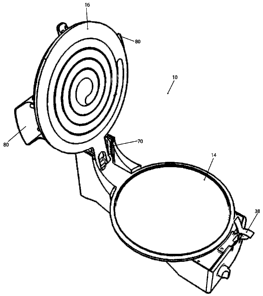
Referring to FIG. 14, an embodiment of a cooking appliance 110 is shown. It
should be appreciated that the embodiment of the cooking appliance 110
illustrated in
FIGS. 14 to 17 may include any of the features disclosed with respect to
cooking
appliance 10, but not specifically described with respect to cooking appliance
110. In
this embodiment, the cooking appliance 110 includes a lower heating assembly
114 and
an upper heating assembly 116. A base 112 provides a solid foundation for the
cooking
appliance 110, thereby allowing the cooking appliance 110 to be placed on a
countertop,
tabletop, or any other sufficiently flat and sturdy surface. The base 112 may
be formed of
plastic, metal, metal in which at least a portion is overmolded with plastic,
or any other
material sufficient to support the lower and upper heating assemblies 114, 116
as well as
provide heat insulation to prevent the user from being burned if the base 112
is touched
during operation.
Referring specifically to FIG. 15, the lower heating assembly 114 of the
cooking
appliance 110 is shown. In this embodiment, the lower heating assembly 114
includes a
lower cooking plate 164 defining a lower cooking surface 167. It should be
understood
by one skilled in the art that the lower cooking plate 164 may be round,
square,
triangular, rectangular, oval, or any other shape sufficient to provide a
heated cooking
surface. The lower cooking plate 164 may be made of a substantially non-stick
material,
or the lower cooking plate 164 may include a non-stick surface added to its
surface.
In this embodiment, the lower cooking plate 164 includes a raised edge 166
that is
spaced radially inward from the outer edge of the lower cooking plate 164, as
shown in
FIGS. 14 and 15. The raised edge 166 extends upwardly from the upper surface
of the
lower cooking plate 164, and the raised edge 166 is adapted to be in an
abutting
relationship with the upper heating assembly 116 when the cooking appliance
110 is in an
operative position, as will be discussed below. In one example, during
operation, a batter
22
CA 02663606 2009-04-22
or mixture, for example, used to form a foodstuff is poured or placed onto the
lower
cooking surface 167 within the volume enclosed by the raised edge 166. The
raised edge
166 is configured to contain the batter therewithin to prevent spillage if the
user pours too
much batter onto the lower cooking plate 64.
As illustrated in FIGS. 14 and 15, the lower cooking plate 164 includes a
reservoir
165, located radially outward from the raised edge 166 but radially inward
from the outer
edge of the cooking plate 164. The reservoir 165 is adapted to receive excess
batter not
contained within the raised edge 166. The reservoir provides a secondary
device for
preventing excess batter from spilling out from the lower heating assembly
114. It
should be appreciated that the reservoir is not limited to collecting excess
batter, the
reservoir may collect, grease or fat from a cooking meat, or any other
foodstuff by-
product or element. It should also be appreciated that in various other
embodiments, the
cooking appliance 110 does not include the raised edge 166, but still includes
reservoir
165. In these embodiments, the cooking appliance 110 is configured such that
excess
batter, for example, flows directly from lower cooking surface 167 into
reservoir 165,
which is recessed to collect excess batter. In further embodiments, the
cooking appliance
110 does not include a reservoir that is recessed relative to the lower
cooking surface 167,
but rather, includes a cooking region that is recessed within the overall
lower cooking
plate, the region including a perimeter wall. In such embodiments, the cooking
appliance
110 is configured such that adequate tolerance exists between the perimeter
wall and the
upper cooking surface 90, such that the upper cooking surface 90 has clearance
to
translate in a substantially vertical manner into the recessed cooking region
of the lower
cooking plate. This tolerance may be any suitable tolerance. In one
embodiment, the
tolerance enables excess batter to flow into the region between the upper
cooking surface
90 and the perimeter wall when the cooking appliance 110 is in a closed
position such
that batter does not spill out of the cooking appliance 110.
Still referring to FIG. 15, in this embodiment, the lower heating assembly 114
includes a resting aperture 108 and a receiving aperture 109 both operable to
receive a
guide post 106. The function of the resting aperture 108 and the receiving
aperture 109
in relation to the guide post 106 will be discussed in more detail below in
the description
of various operative positions of the cooking appliance 110. The lower heating
assembly
further includes female stabilizing members 107a configured to receive male
stabilizing
23
CA 02663606 2009-04-22
members 107, discussed in more detail below. It should be appreciated that the
female
stabilizing members 107a may be structurally integrated with the lower cooking
plate 164
or may be attached to the lower cooking plate. It should be appreciated that
in various
other embodiments, the cooking appliance 110 need not include male and females
stabilizing members 107 and 107a.
The lower heating assembly 114 further includes a hinge assembly 101. FIG.
16A provides a detailed exploded view of the hinge assembly 101. The hinge
assembly
101 includes a rear support member 169. Hinge support members 168 extend from
rear
support member 169. Hinge support members 168 each define a track 171
configured to
receive a hinge pin 102. In various embodiments, the hinge pins 102 may be
surrounded
by a bearing or sleeve, to minimize friction between the hinge pins 102 and
tracks 171.
The tracks 171 each include a substantially horizontal portion and a
substantially vertical
portion extending from the substantially horizontal portion. The substantially
vertical
portion extends in a substantially perpendicular manner relative to the
cooking surface of
the lower cooking plate 164. It should be appreciated that although in this
embodiment
the tracks 171 are substantially L-shaped, the tracks 171 may be any suitable
shape and
extend any suitable direction. As illustrated in Fig. 16A, in this embodiment,
the bottom
of the tracks 171 are open, such that the hinge pins 102 may slide directly
into the tracks
171 for ease of assembly. In this embodiment, the base 112 of the cooking
appliance 110
defines the bottom of the tracks 171 when the cooking appliance 112 is
assembled. It
should be appreciated that in other embodiments, the bottom of the tracks 171
may not be
open and hinge support members 168 may define the bottom of the tracks 171.
In another embodiment, the tracks 171 include a plurality of notches 174
extending from the substantially vertical portion of the tracks 171, as
illustrated in Fig.
16B. The notches 174 are adapted to receive the hinge pins 102 to selectively
locate and
secure the upper heating assembly 116 at a plurality of heights relative to
the lower
heating assembly 114. It should be understood by one skilled in the art that
the notches
174 may extend from the substantially vertical portion of the tracks 171
forwardly,
rearwardly, or a combination thereof in an alternating or random manner.
On each respective side of the lower heating assembly 114, the lower heating
assembly 114 and hinge support members 168 define a slot 123. Each slot 123 is
configured to receive one of the hinge pin support members 104. The hinge
assembly
24
CA 02663606 2009-04-22
101 includes a top plate 103 which connects to the hinge support members 168
and the
rear support member 169. It should be appreciated that in various other
embodiments,
the hinge assembly 101 need not include rear support member 169 or the top
plate 103
and hinge support members 168 may be connected by any suitable surface or
connecting
member. In this embodiment the top plate 103 is not connected to the lower
cooking
plate 164. In other embodiments, the top plate 103 and the lower cooking plate
164 may
form one structure. It should be appreciated that in embodiments in which the
hinge
assembly 101 is not connected to the lower cooking plate 164, an insulating
member may
be placed between hinge assembly 101 and lower cooking plate 164.
Hinge pin support members 104 extend downward from the upper heating
assembly 116. In this embodiment the pin support members 104 extend directly
from the
upper cooking plate 186. In various other embodiments, the pin support members
104
extend from a surface which is not part of, but which borders the upper
cooking plate
186. It should be appreciated that in embodiments in which the upper cooking
plate 186
is not connected to the surface from which the pin support members 104 extend,
an
insulating member may be placed between upper cooking plate 186 and the
surface from
which the pin support members 104 extend. Hinge pins 102 extend inwardly from
hinge
pin support members 104. When the upper and lower heating assemblies 114 and
116 are
operatively coupled together, pins 102 reside in tracks 171. Pins 102 are
sized such that
adequate clearance remains between the outer perimeter of the pins 102 and
tracks 171 to
allow substantially resistance-free movement of the hinge pins 102 relative to
the tracks
171, and hence substantially resistance-free movement of the upper heating
assembly 116
relative to the lower heating assembly 114. Similarly, sufficient clearance
exists between
hinge support members 168 and hinge pin support members 104 to allow
substantially
resistance-free movement of the upper heating assembly 116 relative to the
lower heating
assembly 114.
The hinge pins 102 allow the upper heating assembly 116 to translate in a
substantially vertical manner relative to the lower heating assembly 114,
wherein the
upper cooking surface 190 may be maintained in a substantially parallel
relationship
relative to the lower cooking surface 167. The hinge pins 102 also allow the
upper
heating assembly 116 to rotate about the axis formed by the hinge pin 102
relative to the
lower heating assembly 114, wherein the upper cooking surface 190 may be
located in an
CA 02663606 2009-04-22
angled position relative to the lower cooking surface 167. Also, the hinge
pins 102 allow
the upper heating assembly 116 to translate in a substantially horizontal
manner relative
to lower heating assembly 114.
It should be appreciated that in various embodiments (not shown), lower
cooking
plate 164 may be removable and interchangeable such that the user may remove
or
replace the lower cooking plate 164 having a flat lower cooking surface 167
with a lower
cooking plate 164 having a different patterned lower cooking surface 167.
FIGS. 14 and 17 illustrate the upper heating assembly 116 of cooking appliance
110. The upper heating assembly 116 includes, among other components, an upper
cover
72, a pair of handles 180, a guide post 106, and a light 130. A lower side of
the upper
heating assembly 116, as illustrated in FIG. 14, includes male stabilizing
members 107,
an upper cooking plate 186 and an upper cooking surface 190 including a raised
pattern
192.
In various embodiments, the light 130 may be a variety of colors and serve a
variety of purposes. In one embodiment, the light 130 illuminates when the
cooking
appliance 110 is on. In other embodiments, the light may serve as: (a) a pour,
or "cook,"
light, illuminating when the lower cooking surface 167 has reached or rises
above a
designated temperature, such as for example, 215 F; (b) an "ON" light,
indicating that
the heating element is heating one of the upper and lower cooking surfaces 167
and 190;
(c) a timer light, illuminating when a designated amount of time has elapsed
from a
designated starting time; or (d) any other suitable indication mechanism. It
should be
appreciated that the cooking appliance 110 may include multiple lights, each
of the lights
individually capable of illuminating in different colors for different
purposes. Further, it
should be appreciated that although FIG. 17 illustrates a light 130 on the top
of the
cooking appliance 110, one or more lights may be located anywhere on the
cooking
appliance 110 in various other embodiments.
In this embodiment, the upper heating assembly 116 includes a pair of opposing
handles 180. The handles may be attached to the upper cover 72 or formed as
one unit
with the upper cover, as illustrated in FIG. 17. The handles 180 extend
laterally from
opposing sides of the cover 72. The handles 180 allow the user to lift the
upper heating
assembly 116 relative to the lower heating assembly 114.
26
CA 02663606 2009-04-22
In one embodiment, a guard extends downward from at least a portion of the
upper heating assembly 116 over the edges of the upper cooking plate 186,
which
protects a user from burns. The guard may be composed of any suitable
insulating
material and may be any suitable shape. In various embodiments, the guard may
be
structurally part of the upper cover 72 or be attached to the upper cover 72.
The upper heating assembly 16 also includes a guide post 106 which extends
from
the upper cooking plate 186, as illustrated in FIGS. 14 and 17. It should be
appreciated
that in this embodiment, the guide post 106 may be attached to the upper
cooking plate
186 and is composed of a different material than the upper cooking plate 186.
It should
be appreciated that in other embodiments, the guide post 106 is attached to
other surfaces
of the upper heating assembly 116. Further, it should be appreciated that the
guide post
106 may be structurally integrated with and/or made of the same material as
the upper
cooking plate 186. In other embodiments, the guide post 106 could be removable
from
upper heating assembly 106, for replacement, cleaning or other purpose.
Additionally, in
another embodiment, the guide post 106 could be adjustable to various lengths.
This
could be accomplished by, for example, a telescoping guide post (not shown);
multiple
sized guide posts 106 which are interchangeable; or any other suitable guide
post design.
In this embodiment, the guide post 106 is substantially rectangular, tapering
as it
extends downward from the upper heating assembly 116. It should be appreciated
that in
various other embodiments, the guide post may be any of: (a) circular; (b)
square; (c)
polygonal; (d) or any other suitable shape.
It should be appreciated that in other embodiments, the guide post may be
composed of two portions, each of the portions being different materials. For
example, in
one embodiment, a first portion of the guide post 106 is stainless steel and a
second
portion of the guide post 106 is plastic. In various such embodiments, the
guide post 106
could include any number portions composed of any suitable materials. In
various other
such embodiments, each of the portions of the guide post 106 could have
different
perimeters or diameters. For example, in one such embodiment in which each of
two
portions of the guide post 106 are circular, a first portion of the guide post
106 extending
directly from the upper cooking plate 106 could have a first diameter and a
second
portion of the guide post 106 extending from the first portion of the guide
post could have
a second diameter which is smaller than the first diameter.
27
CA 02663606 2009-04-22
Additionally, as discussed with respect to the lower heating assembly 114, the
upper heating assembly 116 includes male stabilizing members 107, which
extends from
the upper cooking plate 186. The female stabilizing members 107a are
configured to
receive the male stabilizing members 107. As in the case of the guide post
106, the male
stabilizing members 107 may be structurally integrated with or attached to the
upper
cooking plate 186 and may be composed of the same or a different material than
the
upper cooking plate 186.
Further, it should be appreciated that, although in this embodiment, the
cooking
appliance 110 includes one guide post 106 and two male stabilizing members
107, the
cooking appliance 110 may include any number of guide posts and male
stabilizing
members. Also, although in this embodiment, the guide post 106 extends from
the front
of the upper heating assembly 116, in other embodiments, the upper guide post
or posts
may, in addition to the male stabilizing members 107, extend from any portion
of the
upper heating assembly 116. Similarly, the lower heating assembly 114 may
define
receiving apertures or female stabilizing members 107a at any location to
receive each of
these respective guide posts or male stabilizing members 107.
It should be understood by one skilled in the art that the upper cooking plate
186
may be round, square, triangular, rectangular, oval, or any other shape
sufficient to
provide a heated cooking surface. In one embodiment, the lower thermostat
assembly 56
controls the temperature of the lower and upper cooking surfaces 167, 190. In
another
embodiment, the temperature of the lower cooking surface 167 is controlled by
the lower
thermostat assembly 56 and the temperature of the upper cooking surface 190 is
controlled by an upper thermostat assembly (not shown). The upper cooking
plate 186
may be made of a substantially non-stick material, or the upper cooking plate
186 may
include a non-stick surface added to its surface.
As illustrated in FIG. 14, the upper cooking surface 190 includes a raised
pattern
192 having a spiral shape. It should be appreciated that the cooking appliance
110 may
be utilized to cook any foodstuff or type of food with any shape or pattern on
one or both
of the top and bottom surface of the foodstuff. Patterns for one or both of
the upper and
lower cooking assemblies could include features, including but not limited to:
(a) straight
lines; (b) curved lines; (c) concentric circles; (d) overlapping circles; (e)
concentric
squares; (f) overlapping squares; (g) concentric ovals; (h) overlapping ovals;
(i)
28
CA 02663606 2009-04-22
concentric diamonds; (j) overlapping diamonds; (k) concentric polygons; (1)
overlapping
polygons; (m) a spiral shape; (n) circles; (o) squares; (p) ovals; (q)
diamonds; and (r)
polygons. Examples of such pattern elements are illustrated in Fig. 23.
In various embodiments, one or both of the upper heating assembly 116 and the
lower heating assembly 14 may include one or more vents which enhance air
circulation
or serve any suitable air flow purpose.
In operation, the cooking appliance 110 includes three primary operative
positions
in which the upper heating assembly 116 may be selectively located at a
different
position or orientation relative to the lower heating assembly 114. Each of
the operative
positions provides the cooking appliance 110 with operational advantages,
thereby
allowing a user to cook a variety of different foodstuffs or allowing the user
to
manipulate the foodstuff being cooked by selectively relocating the upper
heating
assembly 116 between the operative positions.
In a first operative position, the upper heating assembly 116 is located at an
angle
relative to the lower heating assembly 114, as shown in FIG. 14. In the first
operative
position, the pins 102 are resting at the intersection of the substantially
vertical portion
and the substantially horizontal portion of the tracks 171. The first
operative position
allows a user to open the cooking appliance 110 to add a foodstuff onto the
lower
cooking surface 167. The first operative position also allows the user to
utilize only the
lower cooking surface 167 to cook a foodstuff.
In a second operative position, the upper heating assembly 116 is lowered
until
the bottom of guide post 106 abuts the bottom of the resting aperture 108. The
resting
aperture 108 is configured such that the guide post 106 does not extend all
the way into
the aperture. When the guide post 106 is resting in the resting aperture 108,
the upper
heating assembly 116 is substantially parallel to but spaced above the lower
cooking
surface 167. It should be understood by one skilled in the art that when in
the second
operative position, the upper cooking surface 190 may be spaced apart from the
lower
cooking surface 167 any distance sufficient to allow the foodstuff to be
cooked using
both the upper and lower cooking surfaces 167, 190 while the upper cooking
surface 190
is secured in a substantially parallel relationship relative to the lower
cooking surface
167. In the second operative position, the upper cooking surface 190 may, but
does not
have to, contact the foodstuff being cooked.
29
CA 02663606 2009-04-22
To get the cooking appliance 110 into this second operative position from the
first
operative position illustrated in FIG. 14, a user grasps the handles 180,
rotates the upper
heating assembly 116 such that it is substantially parallel to the lower
heating assembly
114, pulls the upper heating assembly 116 forward until the guide post 106 is
above the
resting aperture 108, and allows the guide post 106 to rest in the resting
aperture 108. It
should be appreciated that when in the second operative position, the pins 102
are at the
ends of the substantially horizontal portions of the tracks 171 which
correspond to the
front of the cooking appliance 110. As the user pulls the upper heating
assembly 116
forward, the pins 102 travel forward along the substantially horizontal
portion of the
tracks 171. It should be appreciated that in the second operative position,
the upper
cooking assembly may or may not contact the food item. In one embodiment, the
upper
heating assembly 116 may include a weight comprised of any suitable material
placed at
a designated position in the upper heating assembly 116. In various
embodiments, the
weight is positioned to assist in guiding the upper heating assembly 116 from
the first
operative position to the second operative position.
In fact, in one example during operation, a user could cook a meat item, such
as a
hamburger, in the cooking appliance 110 in the second operative position,
wherein the
upper heating assembly 116 does not contact the top surface of the hamburger.
In the
second operative position, the upper heating assembly 116 is substantially
parallel to the
lower heating assembly 114, allowing uniform convection along the top of the
hamburger, and accordingly, fat to drain proportionally from the top of the
hamburger
down.
In one embodiment, which could be utilized in the above example, the lower
cooking plate 164 is concave downward, with a flat plateau configured to
accommodate a
foodstuff on its top. Fat, or any other foodstuff byproduct, would drain from
the plateau,
down the concave surface of the lower cooking plate 164, and ultimately into
the
reservoir 165. An example of such a lower cooking plate 164 is illustrated in
Fig. 20.
This lower cooking plate 164 could be interchangeable with any of the other
cooking
plates disclosed herein or configured such that it rests on top of any of the
lower cooking
plates disclosed herein.
Lowering the upper heating assembly 116 into a third operative position from
the
second operative position may compress the foodstuff disposed on the lower
cooking
CA 02663606 2009-04-22
surface 167. In one example, this could cause batter to spread out along the
lower .
cooking surface 167 within the volume defined by the raised pattern 166. In
one
embodiment, the upper heating assembly 116 is lowered into an abutting
relationship
with the lower heating assembly 114 by grasping the handles 180 and
translating the
__ upper heating assembly 116 in a substantially vertical direction such that
the hinge pins
102 translate along the substantially vertical portion of the tracks 171. When
the cooking
assembly 110 is in the third operative position, the hinge pins 102 are
disposed at the
lowermost location within the substantially vertical portion of the tracks
171. In this
embodiment, the upper heating assembly 116 is in the second operative position
before
__ being moved to the third operative position. However, it should be
appreciated that in
various other embodiments, the upper heating assembly 116 may be moved
directly from
its position in the first operative position to that of the third operative
position, or any
other suitable position.
As discussed, when in the second operative position, the guide post 106 rests
in
__ the resting aperture 108. To get to the third operative position, the user
grasps the
handles 180 and slides the upper heating assembly 116 backwards until the
guide post
106 is over the receiving aperture 109. As the upper heating assembly 116 is
sliding
backwards, the pins 102 travel along the substantially horizontal portion of
the tracks
171. Once the guide post 106 is above the receiving aperture 109, the user
lowers the
__ upper heating assembly downward, such that the pins 102 slide downward
along the
substantially vertical portion of the tracks 171 and the guide post 106 is
lowered into the
receiving aperture 109. Configuring the cooking appliance 110 such that the
user has to
have the cooking appliance 110 in the second operative position before moving
it to the
third operative position and incorporating the guide post 106 ensures that the
upper
heating assembly 116 translates towards the lower heating assembly 114 in a
substantially vertical manner. Or stated alternatively, such that the upper
heating
assembly 116 is substantially parallel to the lower heating assembly 114 as it
translates
relative to the lower heating assembly 114. There are other ways this may be
accomplished as well. For example, in the embodiment illustrated in Fig. 21, a
plurality
__ of substantially horizontal guides 106c extend from the upper heating
assembly 116 and a
plurality of pairs of guide posts 109a extending substantially upward from the
lower
heating assembly 114 define a plurality of respective apertures which are
configured to
31
CA 02663606 2009-04-22
receive the substantially horizontal guides 106c. In another embodiment,
illustrated in
Fig. 22, a plurality of guide posts 109b extend from the lower heating
assembly 114 and
the upper heating assembly 116 defines a plurality of apertures 106b, which
are
configured to receive the respective guide posts 109b. It should be
appreciated that
although the embodiments illustrated in Figs. 21 and 22 include three
respective guide
posts and apertures, any number of guide posts and apertures could be utilized
with the
cooking appliance 110.
It other embodiments, the cooking appliance 110 may be moved into the third
operative position directly from the first operative position, such as by use
of a cantilever
assembly, or any other suitable mechanical or electromechanical device. An
example of
a suitable cantilever assembly is that disclosed in U.S. Patent No. 2,057,501.
Another
alternative mechanism for lowering the upper heating assembly 116 could be
that
disclosed in U. S . Publication No. 2006/0213373 .
While three operative positions for cooking assembly 110 are described above,
additional operative positions of the upper heating assembly 116 relative to
the lower
heating assembly 114 may be obtained through modification of elements
described
above, such as the tracks 171 or the guide post 106 that would be understood
by one
skilled in the art. It should also be understood by one skilled in the art
that the lower
cooking surface 167 may be used to cook a foodstuff alone or in combination
with the
upper cooking surface 190, depending upon the application for which the
cooking
appliance 110 is being used and the operative location at which the upper
heating
assembly 116 is located.
Referring now to FIGS. 18 and 19. Each of the foregoing embodiments disclosed
herein include a single respective upper and lower cooking surface. FIG. 18
illustrates a
cooking appliance 210 including six respective upper and lower cooking
surfaces. A
cooking appliance 210 such as that disclosed in FIG. 18 could be used, for
example, to
cook large quantities of food at once. Although the cooking appliance 210
includes legs,
which could be retractable for portability, it should be appreciated that the
cooking
appliance 210 could simply sit on a preexisting table or flat surface without
legs.
FIG. 19 illustrates a cooking appliance 310 which includes two respective
upper
and lower cooking surfaces. Cooking appliance 310 could similarly be used for
event
32
CA 02663606 2009-04-22
catering or for home use, when one wishes to cook more than one foodstuff at
the same
time.
It should be appreciated that the cooking appliances 210 and 310 may include
any
number of upper and lower cooking surfaces and may include any of the features
of and
function in substantially the same manner as the cooking appliances 10 and 110
of the
foregoing embodiments.
In various embodiments, the base 112 includes feet which may or may not be
adjustable. Further, the base 112 may define vents (not shown) which allow
heat to exit
the cooking appliance. In various embodiments, heat transfer may be assisted
by a fan
(not shown).
Although the embodiments disclosed herein include the upper heating assembly
116 being manually raised and lowered relative to the lower heating assembly
114, it
should be appreciated that in various embodiments, the upper heating assembly
116 may
be raised and lowered by a variety of devices including, but not limited to:
(a)
electromagnetic devices; (b) hydraulic devices; (c) DC servo motors; (d)
gear/chain
mechanisms; (e) air pistons; and (f) any suitable devices.
It should further be appreciated that the cooking appliance 110 may include a
memory device storing a plurality of instructions and a processor, wherein the
processor
is programmed to execute the plurality of instructions to cause the cooking
appliance 110
to perform a variety of automated tasks, including each of the motions and
functions
described herein. Examples of such a processor are disclosed in U.S. Patent
Nos.
5,934,182, 6,549,818 and 6,813,575. The cooking appliance 110 may further
include
various sensors in electronic communication with the processor including: (a)
heat
sensors; (b) position sensors; (c) light sensors; and (d) any other suitable
sensors. In one
embodiment, a timer may send a signal to a processor, wherein the processor is
programmed to cause the cooking appliance 110 to automatically shutoff after a
predetermined amount of time has passed since the cooking appliance 110 was
turned on
or a designated event has taken place.
In the various embodiments disclosed herein, the cooking appliance is powered
by
a wall plug. It should be appreciated that in various other embodiments, the
cooking
appliance could include a battery power supply. In one embodiment, the battery
could be
rechargeable. In another embodiment, the cooking appliance could include a
solar power
33
CA 02663606 2009-04-22
supply. An example of such a solar power supply is the Sunforce 13 Watt
Folding Solar
Panel, Model #500384, available at www.northerntool.com, of course subject to
being
sized to power the subject invention. The cooking appliance 110 could also be
connected
to a larger solar panel, such as the Sunforce Solar Charging Kit ¨ Solar
Module, 125
Watt, also available at www.northerntool.com. A cooking appliance 210, such as
that
illustrated in FIG. 18, could have a solar panel on top of the upper heating
assembly
which captures and stores solar energy, which subsequently is converted and
powers the
heating elements of the cooking appliance. The use of solar power would enable
use of
such a cooking appliance 210 at large outdoor events in remote areas, absent
the need for
a battery or generator. The cooking appliance may also be linked to a fuel
cell power
supply. It should be appreciated that although use of solar power and fuel
cells is
proposed as a power supply, the cooking appliance may still be successfully
powered by
a battery or generator.
While preferred embodiments of the invention have been described, it should be
understood that the invention is not so limited and modifications may be made
without
departing from the invention. The scope of the invention is defined by the
appended
claims, and all devices that come within the meaning of the claims, either
literally or by
equivalence, are intended to be embraced therein.
34