Note: Descriptions are shown in the official language in which they were submitted.
CA 02663662 2014-10-23
- 1 -
RAPID INVERSION OF ELECTROMAGNETIC
RECONNAISSANCE SURVEY DATA
[0001]
FIELD OF THE INVENTION
[0002] The present invention relates generally to the field of
geophysical
prospecting, and more particularly to processing data from a controlled-source
electromagnetic ("CSEM") survey of a subterranean region. Specifically, the
invention is a method for rapid inversion of electromagnetic data for physical
properties of the subsurface medium, such as subsurface rock
conductivity/resistivity
which is useful in hydrocarbon prospecting.
BACKGROUND OF THE INVENTION
[0003] The CSEM technique is an important geophysical tool for
hydrocarbon prospecting in the earth's subsurface. In a CSEM survey, an
electromagnetic-wave source (transmitter) generates an electromagnetic wave.
The
electromagnetic signal induced in the earth by the transmitter is recorded
constantly
in time by one or more receivers. The electromagnetic signal at a receiver
location
depends on physical properties, especially the electrical properties, of the
medium in
which the electromagnetic wave has passed through from the source to the
receiver.
The behavior of this signal as a function of frequency and transmitter
location or
separation (offset) between transmitter and receiver can be used to estimate
the
spatially varying resistivity model of the subsurface within a certain depth
range.
This estimated subsurface resistivity model is used for identifying
resistivity
anomalies indicating the presence of hydrocarbons (oil or gas) in the earth's
subsurface.
[0004] Figure 1 illustrates a typical marine CSEM survey in which a
constantly active electromagnetic-wave transmitter 11 is towed below the water
surface 15 along a line 12 above electromagnetic receivers 13 (two neighboring
CA 02663662 2009-03-12
WO 2008/033184- 2 - PCT/US2007/016986
receivers are shown) deployed on the seafloor 14. Reference number 16
indicates the
offset between the right-most receiver and the source when the source is at
location
11A. For more details see Chapter 12, page 931 in Investigations In Geophysics
No.
3, Electromagnetic Methods In Applied Geophysics, volume 2, edited by Misac N.
Nabighian, Society of Exploration Geophysicists, 1991). Alternative
configurations
include stationary transmitters on the seafloor or in the water column as well
as
magnetic transmitter antennae and connecting several receivers in a towed
array (see,
for example, U. S. Patent No. 4,617,518 to Smka). The receivers typically have
multiple sensors designed to record different vector components of the
electric and/or
magnetic fields. A sensor is also called a channel. The data recorded in one
channel
correspond to one vector component of the electromagnetic field. Every
receiver
records the electromagnetic signal constantly in time during a survey. The
data
recorded by one sensor at a receiver location are normally called a common-
receiver
gather, or simply called a receiver gather. Under
the stationary-receiver
configuration, a common-receiver gather represents the electromagnetic signal
at the
fixed receiver location induced by the source at all different source
locations, or at
different times during the survey. Similarly, data can also be sorted in
common-
source gathers to represent the electromagnetic field at those receiver
locations from a
source at a fixed source location.
[0005] Marine
CSEM data are typically interpreted in the temporal frequency
domain. After taking out the frequency-dependent effects of the source and the
receiver themselves, the signal at a frequency represents the response of the
earth to
electromagnetic signal at that temporal frequency. It is this response that
provides us
information about the subsurface electrical properties. Like any other type of
wave,
the electromagnetic signal in a CSEM survey has two attributes, amplitude and
phase.
The signals are therefore conveniently represented as complex numbers in
either
rectangular (real-imaginary) or polar (amplitude-phase) form.
[0006] In
practice, the receiver data are usually converted to temporal
frequency by dividing (or "binning") the recorded time-domain data into time
intervals (i.e. bins: xl, x2, and x3 as shown in Fig. 2A) and determining the
spectrum
within each bin by standard methods based on the Fourier Transform. The signal
CA 02663662 2009-03-12
WO 2008/033184 PCT/US2007/016986
- 3 -
recorded by a receiver is 21 and, for reference, the transmitted periodic
waveform 22
is also shown. Figure 2B shows the amplitudes of the spectral components from
the
bin x3. Unlike the example shown in Fig. 2A, a typical bin length is several
periods of
the transmitter waveform. Each bin might correspond to a different position of
the
source arrow 11 in Fig. 1. Some methods of transforming data to the time-
frequency
domain include the Short-Time Fourier Transform (J. Allen, L. Rabiner, "A
Unified
Approach to Short-Time Fourier Analysis and Synthesis," Proc. of the IEEE 65,
1558-64, (1977)); and the Choi-Williams transform (H. Choi and W. Williams,
"Improved time-frequency representation of multicomponent signals using
exponential kernels," IEEE Trans. on Acoust., Speech, and Signal Processing,
37,
862-871,(1989)). In the temporal-frequency domain, signals recorded by a
receiver,
including both amplitude and phase, of each of the temporal-frequency
components
are functions of bin, or the transmitter location, or the signed offset
distance between
source and receiver. Figures 3A-B show an example of amplitude (3A) and phase
(3B) variation versus transmitter-receiver offset at frequency 3/8 Hz. The
drawings
represent model calculations with the solid-line curves representing a
resistivity
model containing a hydrocarbon (high resistivity) layer, whereas the dashed
line
curves were generated using a resistivity model without a reservoir. As shown
in the
drawings, both the phase and amplitude of CSEM data can be indicative of
resistive
(and potentially hydrocarbon-bearing) strata in the subsurface, and can thus
be used to
estimate the subsurface rock electrical conductivity or resistivity.
Hydrocarbon
bearing rocks usually show higher resistivity than the surrounding sediments.
The
differences between the solid-line curves and the dashed-line curves show how
CSEM
data may be used to detect the presence of hydrocarbons. Thus, the subsurface
rock
resistivity information derived from the CSEM data is valuable for hydrocarbon
exploration risk reduction.
[0007] The estimation of the subsurface resistivity (or conductivity)
model in
three-dimensional (3-D) space from measured CSEM data is an inverse problem.
Solving an inverse problem is a trial-and-error iterative process. The final
estimated
model should be able to predict data that match the measured data and satisfy
any
constraints that may be applicable to the model.
CA 02663662 2014-10-23
-4-
100081 This process (i.e. updating the resistivity model for the next
iteration) can
be either human-guided manual adjustment of the subsurface resistivity model
or an
automatic model update predicted from some appropriate mathematical measures
of the
misfit between measured and the predicted data. See for example, G. A. Newman
and
D. L. Alumbaugh, "Three-dimensional massively parallel electromagnetic
inversion¨ I.
Theory," Geophys. J. Int., 128, 345-354 (1997) and Y. Sasaki, "Full 3-D
inversion of
electromagnetic data on PC," J. of Applied Geophys., 46, 45-54, (2001), or a
combination of the two. The prediction of electromagnetic data from a
resistivity model
of the subsurface is achieved by numerically solving Maxwell's electromagnetic
field
equations, a process called forward modeling.
[0009] In many examples of CSEM hardware, data cannot be effectively
recorded at the nearest offsets because the dynamic range of the receiver's
digitizers is
too small to accommodate the large dynamic range of the data. This region is
sometimes
known as the "saturation zone" and typically encompasses source-receiver
offsets of
less than 500 meters depending on amplifier property of the receiver. An
example is
shown in Figure 3A, in which constant amplitude is observed for offset roughly
within
500m.
[0010] The inversion of CSEM data for the subsurface conductivity is a
computationally intensive process, since it involves many forward simulations
of the
electromagnetic field in multi-dimensional space. To speed up the inversion
process in
multi-dimensional space, such as 2-D or 3D space, the model-update prediction
is
derived from the forward modeling and the transmitter-receiver reciprocity
property can
be used to reduce the number of forward modeling operations; see the
previously cited
Newman and Alumbaugh reference. By using the reciprocity principle (switching
the
role of a transmitter and a receiver), the electromagnetic fields in one
entire receiver
gather (as shown in Figs. 3A-B) can be obtained in one forward modeling
operation by
calculating the electromagnetic fields at those original transmitter locations
from a
transmitter located at the original receiver location. In the traditional
frequency-domain
inversion process, every receiver gather needs to be forward simulated
separately and
compared to the measured data. The number of receiver gathers to be
CA 02663662 2009-03-12
WO 2008/033184 PCT/US2007/016986
- 5 -
simulated in a survey is the product of the number of receivers deployed,
frequencies
to be used, and the number of components of each receiver. If the inversion is
performed in time domain, the number of forward simulations is proportional to
the
number of receiver or source gathers in a survey depending on whether the
transmitter-receiver reciprocity is used. The large number of independent
forward
simulations required in the current inversion techniques discourages its
application to
large 3-D surveys, such as reconnaissance surveys covering large area with
regularly
spaced receivers as illustrated by an example in Fig. 4. Techniques leading to
a
substantial speedup of CSEM data inversion in multi-dimensional space are
crucial
for its application in 3-D surveys. The present invention fulfills this need.
[0011] Figure 4 shows a surface map view of a typical data acquisition
pattern
for a CSEM reconnaissance survey. The distribution of receivers (indicated by
both
black and white arrows) on a regular 2-D grid is shown as well as a set of
parallel
transmitter towlines (dashed lines); the receiver interval is usually several
kilometers.
Acquiring data along a regular grid is natural for CSEM reconnaissance, where
a
priori information about the subsurface is limited.
[0012] Current methods of CSEM data inversion will next be examined in
somewhat more detail. As previously stated, CSEM data inversion is an
iterative
method for determining the resistivity of the subsurface from CSEM data
measured at
the earth's surface or seafloor. The result of inversion is a geo-electric
model of the
subsurface obtained by updating a starting model of the earth resistivity to
minimize
the mismatch between measured and simulated data. The model update from
iteration
to iteration can be achieved by either human-guided manual adjustment of the
resistivity model or an automatic model update predicted from some appropriate
mathematical measures of the misfit between measured and the predicted data
(see for
example, G. A. Newman and D. L. Alumbaugh, op. cit.) or a combination of the
two.
[0013] Most of the geological and electrical information that may be
available
about the subsurface, such as structural and rock physical property
information from
seismic data and electrical property information from available well
measurements,
can be taken into account by human-guided manual model updates more easily
than
by automatic model updates predicted from some appropriate mathematical
measures
CA 02663662 2009-03-12
WO 2008/033184- 6 - PCT/US2007/016986
of the mismatch between measured and the predicted data. However, the human-
guided manual model update becomes awkward as the survey size and/or the
subsurface geology complexity increases. This is especially true for 3D
inversion due
to the great flexibility in updating the model in 3-D space.
[0014] Most of the current inversion procedures adopt some automatic
model-
update schemes based on numerical optimization procedures which adjust
subsurface
resistivities and possibly other parameters until the defined objective
function is
reduced to a sufficiently small value. The objective function usually includes
term(s)
describing the data mismatch between the forward simulated data and the
measured
data and other term(s) describing some geological information inputs and
constraints.
Some model constraints may also be enforced directly in the model-update
process.
The inversion process drives the model along the direction of reducing the
data
mismatch and satisfying any geological constraints included either in the
objective
function or enforced in the model-update process.
[0015] These inverted models from either manual or automatic model-
update
processes should be able to produce synthetic CSEM data that accurately match
the
measured data. Inversions using either of the model-update procedures outlined
above require repeated solution of Maxwell's equations (or forward modeling)
for a
large number of models and transmitter-receiver configurations. The forward
modeling of CSEM data in 3D space is computationally intensive and it
dominates the
computational time and costs in the CSEM data inversion (see, for example, D.
L.
Alumbaugh and G. A. Newman, "3-D massively parallel electromagnetic inversion -
Part II, Analysis of a cross well experiment," Geophys. J. Int. 128, 355-363
(1997)).
Under some simple situations, the subsurface resistivities might be
approximated by a
1-D layered model which limits any variation of resistivity along the
horizontal
direction for more efficient forward modeling and inversion (see, for example,
S.
Constable and C. J. Weiss, "Mapping thin resistors and hydrocarbons with
marine EM
methods: Insights from 1D modeling", Geophysics 71, G43-G51, (2006)). In
general,
such simplification is not accurate enough for application in hydrocarbon
exploration.
[0016] There exist several forward-modeling schemes for the simulation
of
electromagnetic wave propagation. The commonly-used ones for general 3-D
models
CA 02663662 2009-03-12
WO 2008/033184 PCT/US2007/016986
- 7 -
are the finite-difference method, hereinafter "FDM", the finite element
method,
hereinafter "FEM", and the integral equation method, hereinafter "IEM." These
are
the standard approaches for numerically solving any partial differential
equation(s)
that cannot be solved analytically. In practical applications of these
methods, the
physical properties, such as the resistivity and dielectric permittivity, are
represented
by discrete cells in the whole space of interest, or in a localized zone for
some special
applications of the IEM. The governing equations, Maxwell's equations for CSEM
applications, are represented in discrete forms on the cell grids for both FDM
and
FEM and are used to solve the electromagnetic field numerically over the cell
grids.
The FDM normally uses rectangular cells without assuming any particular
geometric
structures of the physical property in space (G. A. Newman and D. L.
Alumbaugh, op.
cit.). The FEM normally uses more general geometric shapes than rectangles
(J.H.
Coggon, "Electromagnetic and Electrical Modeling by Finite Element Method",
Geophysics 36, 132-155 (1971)) that are able to represent the model in more
detail
than the FDM at the expense of more complex model representation and governing
equations over the cell grids.
[0017] The IEM recasts the system of differential equations implied by
Maxwell's equations into an associated integral equation by making use of the
properties of the Green's function for the electric and/or magnetic field in a
uniform
or layered model. A uniform or layered material is typically used for the
reference
Green's function because highly accurate and rapidly computed solutions are
available for these models. The resulting integral equations naturally give
rise to
computational schemes that work very well for compact objects imbedded in a
uniform or layered background (such as a ship in the deep ocean or an aircraft
high in
the atmosphere).
[0018] The forward modeling methods described in the preceding
paragraphs
can be applied in both time and frequency domain (for time domain example, see
for
example, M. Commer and G. A. Newman, "A parallel finite-difference approach
for
3D transient electromagnetic modeling galvanic sources", Geophysics. 69, 1192-
1202
(2004)). Forward modeling CSEM data in the time domain offers advantages in
handling the so-called air-wave effect in land or shallow water surveys (the
air wave
CA 02663662 2009-03-12
WO 2008/033184 PCT/US2007/016986
- 8 -
is the direct transmission from the broadcasting antenna to the detecting
antenna
through the air). However, it is computationally more costly than in frequency
domain due to the large number of time steps needed to simulate the
propagation of
electromagnetic waves in the model.
[0019] All of the preceding forward-modeling approaches in frequency
domain result in a very large linear system to solve. The large size of the
linear
system combined with the large number of forward modelings needed for a survey
makes the forward modeling time consuming. A powerful computer is often needed
in order to obtain results in a reasonable time. A number of techniques have
been
developed to speed up the computation at different stages of the inverse
process. For
example, more efficient optimization techniques such as the non-linear
conjugate
gradient (NLCG) solver, multi-grid solvers, approximate computation of the
sensitivity matrix, source¨receiver reciprocity, etc. All those techniques are
helpful,
but more improvements are needed to make electromagnetic inversion in 3D space
a
routine practice with reasonable computer resources.
SUMMARY OF THE INVENTION
[0020] In one embodiment, the invention is a computer-implemented
method
for rapid inversion of electromagnetic data from a controlled source
electromagnetic
survey of a subterranean region, comprising:
(a) summing measured electromagnetic survey data to form one or more
composite gathers, each composite gather being formed from at least two
selected
ordinary gathers, said ordinary gathers being either common-receiver or common-
source gathers; and
(b) inverting the composite gathers for a subsurface electrical-property
parameter such as resistivity.
BRIEF DESCRIPTION OF THE DRAWINGS
[0021] The present invention and its advantages will be better
understood by
referring to the following detailed description and the attached drawings in
which:
CA 02663662 2009-03-12
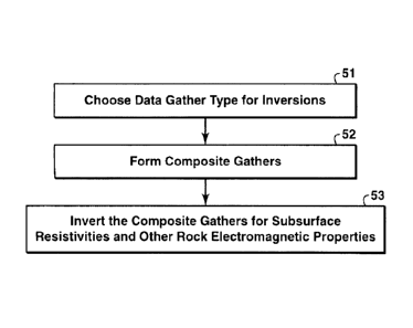
WO 2008/033184 PCT/US2007/016986
- 9 -
[0022] Fig. 1 is a schematic plot of a marine CSEM survey with multi-
component electromagnetic receivers located on the sea floor;
[0023] Figs. 2A-B illustrate the process of binning a receiver signal
in time
and determining the frequency spectrum within each bin by Fourier analysis;
[0024] Fig. 3A shows the effect of a resistive reservoir on amplitude
and the
saturation zone near the receiver location (absolute offset roughly less than
500m),
and Fig. 3B shows the effect of a resistive reservoir on phase;
[0025] Fig. 4 shows receiver deployment and transmitter tow lines for
a
typical reconnaissance marine CSEM survey;
[0026] Fig. 5 is a flow chart showing basic steps in the present
inventive
method;
[0027] Fig. 6 is a flow chart showing basic steps in composite gather
formation in an embodiment of the invention using receiver gathers;
[0028] Fig. 7 is a flow chart showing basic steps in electromagnetic
data
inversion in one embodiment of the present invention;
[0029] Figs. 8A-B illustrate how two common-receiver gathers are
summed to
form a single composite gather;
[0030] Figs. 9A-F illustrate various transmitter and receiver antenna
combinations that can be used to form multi-receiver gathers in the present
invention;
[0031] Figs. 10A-C show summed electric field amplitudes of one
frequency
component from receiver gathers at different separations, illustrating the
domination
by near-offset data in a composite gather with closely spaced receivers;
[0032] Figs. 11A-B illustrates how reduction of data overlap in
composite
gather formation can sometimes be achieved by using different channels
(different
electromagnetic field components);
[0033] Figs. 12A-C illustrate how data phase differences can lead to
unwanted
data cancellation when the data are summed in composite gather formation,
unless
phase encoding is used; and
CA 02663662 2014-10-23
.=
- 10 -
[0034] Figs. 13A-D show results of a simulated experiment
to test the present
inventive method.
[0035] The invention will be described in connection with
its preferred
embodiments. However, to the extent that the following detailed description is
specific
to a particular embodiment or a particular use of the invention, this is
intended to be
illustrative only, and is not to be construed as limiting the scope of the
invention. The
scope of the claims should not be limited by particular embodiments set forth
herein,
but should be construed in a manner consistent with the specification as a
wholes.
DETAILED DESCRIPTION OF PREFERRED EMBODIMENTS
[0036] The present invention is designed to speed up
forward modeling and
thus the inversion process by reducing the effective number of forward
synthetics
needed in a survey. This is achieved by simulating multiple transmitter
configurations
simultaneously in one simulation. The present invention is not limited to any
particular
forward-modeling method or methods, or any particular technique(s) of speeding
up
the forward solution for a particular transmitter configuration. It can be
applied jointly
with other techniques to achieve higher speedup factors. The present invention
can be
applied to frequently-used methods, such as the FDM, FEM, and IEM discussed
previously in this document, and in either time or temporal-frequency domain.
[0037] Basic steps of the present inventive method are
illustrated in the flow
chart of Fig. 5. At step 51, the user chooses the data gather type, common-
source (or
transmitter) gather or common-receiver gather, to be used for inversion for a
selected
CSEM survey. At step 52, composite gathers of electromagnetic data are formed
by
using the measured electromagnetic data in the survey according the gather
type
chosen in step 51. At step 53, the composite gathers generated in step 52 are
inverted
for the subsurface electrical-property parameters, such as the resistivity.
[0038] The selection of data in common-source gather or
common-receiver
gather is usually based on consideration of computational efficiency. The
inversion
cost is proportional to the number of gathers to be inverted. A common-source
gather
CA 02663662 2009-03-12
WO 2008/033184 PCT/US2007/016986
-11 -
can be simulated in one forward modeling inside a computer. A common-receiver
gather can also be simulated in one forward modeling in the same way as a
common-
source gather by the application of reciprocity principle (exchanging the role
of
transmitter and receivers). If the number of source (or transmitter) locations
is
smaller than the total number of active recording-channels in the survey,
arranging the
data in common-source (or common-transmitter) gathers will result in fewer
gathers
for the survey; otherwise, arranging the data in common-receiver gathers will
result in
fewer gathers. The data gather type that results in fewer gathers for a given
survey is
usually chosen for inversions. Common-receiver gathers are used in most of the
illustrations of this invention since the number of common-receiver gathers is
typically much smaller than the number of common-source gathers in most
current
CSEM surveys.
[0039] A composite gather is a supercomposition of a certain number of
gathers in a survey to simulate a simultaneously active multi-source
experiment.
When a composite gather is a supercomposition of common-source gathers, the
composite gather may also be called a multi-source (or multi-transmitter)
gather
herein. Similarly, a composite gather is also called a multi-receiver gather
herein
when the composite gather is a supercomposition of common-receiver gathers.
The
electromagnetic data of a composite gather can be obtained in one forward
simulation
similar to the forward simulation of an original gather by activating multiple
sources
simultaneously. The active sources in the forward simulation of the composite
gather
correspond to those sources of the original gathers included in the composite
gather.
The number of composite gathers formed from a survey can be substantially less
than
the number of original gathers in the survey for the same coverage. The
inversion of
the composite gathers is more efficient than the inversion of the original
gathers
included in those composite gathers because of the efficiency of the
underlying
forward simulation.
[0040] Basic steps in forming multi-receiver gathers are illustrated
in Fig. 6.
The data can be in either time or temporal frequency domain. In temporal
frequency
domain, each frequency component needs to be summed separately, and each
synchronized time sample needs to be summed separately in time domain. At step
61,
CA 02663662 2009-03-12
WO 2008/033184 PCT/US2007/016986
- 12 -
a set of transmitter configurations, including both locations and orientations
(such as,
but not exclusively, locations from one towline), from a survey is chosen for
forming
multi-receiver gathers. At step 62, a subset of receiver channels recording
data
induced by the transmitter at locations chosen in step 61 is chosen for
forming a
multi-receiver gather. Preferred ways for selecting the subset of receiver
channels are
described below. For example, the inline component of the electric field might
be the
only receiver channel selected. However, in some embodiments of the invention,
at
least two receiver channels are selected. Figure 9 indicates some of the
possible
combinations of channels that might be chosen. At step 63, at every
transmitter
location selected in step 61, data measured by receiver channels selected in
step 62
are summed together to form a multi-receiver gather corresponding to those
selected
receiver channels. At step 64, it is decided whether to repeat steps 62 and 63
for one
or more different subsets of receiver channels for the chosen set of
transmitter
locations. Steps 61-64 may then be repeated for all other desired sets of
transmitter
locations (step 65).
[0041] The flow chart of Fig. 6 assumes that the data are in common-
receiver
gathers. The procedure of forming composite gathers is the same if the data
are in
common-source gathers except that the roles of transmitter and receiver in
Fig. 6 need
to be exchanged.
[0042] In the selection of a subset of receiver channels to sum at
step 62 in the
flow chart of Fig. 6, a number of techniques can be used in order to sum as
many
gathers together as possible with a controlled level of data overlap between
neighboring gathers in a multi-receiver gather, such as choosing different
subsets for
different frequency components and selecting different components
alternatively from
neighboring receivers. The major factors that need to be considered in making
multi-
receiver gathers include (1) the target depth range desired from inversion;
(2) the
frequency content of the data; and (3) the skin depth (or decay length) of the
electromagnetic field in the background resistivity model of the subsurface.
The
details of these techniques in forming the multi-receiver gathers are
described in part
(B) of the following section.
CA 02663662 2009-03-12
WO 2008/033184 PCT/US2007/016986
- 13 -
[0043] The electromagnetic field value at a transmitter location along
its
orientation in a multi-receiver gather is the summation of the measured field
values by
those receivers, or possibly a phase-encoded version of the measured field
values by
those receivers, at the same transmitter location and of the same transmitter
orientation. (The requirement for the same transmitter orientation has meaning
where
the transmitter is towed alone the same towline twice, but the transmitter
orientations
from the two tows at any of the locations along the towline may be different.
The
data from the two tows cannot be summed together if the orientations are not
the
same.) When the receiver data are encoded with certain phases in the formation
of a
multi-receiver gather, the same encoded phases must be applied to the
corresponding
source signals in the forward modeling of the multi-receiver gather using
multiple
active sources. Data of the same frequency component are summed together if
the
forward modeling is performed in the frequency domain, and data recorded at
the
same time are summed together if the forward modeling is performed in the time
domain. The domain in which the multi-receiver gathers are formed is chosen
according to the domain in which the forward modeling in the inversion is
performed.
The CSEM data need to be transformed to temporal-frequency domain from the
measurement performed in time domain before forming multi-receiver gathers for
performing the inversion of multi-receiver gather data in temporal-frequency
domain.
[0044] The inversion of the multi-receiver gathers is similar to the
inversion
of the original gathers. A typical electromagnetic data inversion procedure is
illustrated by the flow chart of Fig. 7. At step 71, an initial resistivity
model and
possibly models for other rock properties as needed are constructed. Available
information such as well log data, water bottom topography, and seismic data,
is
normally used in the construction of the initial model. At step 72, the
electromagnetic
field in the initial model corresponding to one multi-receiver gather is
modeled by
activating simultaneously all the "sources" (corresponding to receivers in the
field
experiment) included in the multi-receiver gather. The forward modeling is
performed for every multi-receiver gather formed for inversion.
[0045] At step 73, the data mismatch between the simulated data and
the input
multi-receiver-gather data is calculated. Any techniques applied to the
inversion of
CA 02663662 2009-03-12
WO 2008/033184 PCT/US2007/016986
- 14 -
the original gathers can also be applied to the inversion of the multi-
receiver gathers,
such as data being weighted by their amplitude in the data-mismatch
calculation and
any model constraints (or regularization) applied in the inversion for
mitigating the
non-uniqueness of the model solution. At step 74, the data mismatch is
compared to a
preset tolerance level. If the data mismatch reaches the tolerance level, the
current
resistivity model is the final model from the inversion and the inversion
process is
done. Otherwise, the resistivity model is updated at step 75 as the new
initial model
and steps 72-75 are repeated until the pre-selected convergence criterion or
other
stopping condition is met at step 74.
[0046] The inversion and the forward modeling used in the inversion
process
can be performed in either temporal-frequency domain or time domain, and the
flow
chart of Fig. 7 is applicable to both domains. In some applications, the user
may wish
to invert some ordinary gathers along with composite gathers. Next, certain
features
of the invention will be discussed in more detail.
(A) Forming multi-receiver gathers
[0047] The present invention reduces the computation time for
inversion by
reducing the effective number of independent forward simulations. This is
achieved
by summing over measured data at the same frequency from a number of receiver
gathers for the same set of towlines to form a multi-receiver gather.
Electromagnetic
data are generally represented by either complex (as opposed to real) numbers
or
amplitudes and phases. The summation of electromagnetic data generated from a
transmitter at a specific location and recorded by receiver antennae at
different
locations is a direct sum of the measured voltage values across the receiver
antennae
possibly encoded with certain phases in the form of complex numbers at those
receiver-antenna locations. Figure 8A shows two receiver gathers of the inline-
component (along the towline direction) electric field plotted vs. transmitter
position
along the transmitter-towline direction, solid lines at the location of
receiver one and
dashed lines at the location of receiver two. The multi-receiver gather formed
from
the inline-component electric field measured at the two different receiver
locations is
shown in Fig. 8B. Two different frequency components, labeled as fi and f2 on
the
plots, are shown (f <12). The gathers shown in Fig. 8B are amplitude curves
formed
CA 02663662 2009-03-12
WO 2008/033184 PCT/US2007/016986
- 15 -
by summing, one frequency at a time, the electric-field curves of the two
receivers
whose amplitude curves are shown in Fig. 8A. The effect of this summing is
clearly
shown by the result for frequency fi between receiver one and receiver two.
The
effect of the summation at other locations is too small to be clearly observed
in this
example. Data below background noise level 81 and above the receiver
saturation
level 82 are muted in the plots as indicated by the two horizontal dotted
lines.
[0048] After using the reciprocity principle (or exchanging the role
of
transmitters and receivers for the purpose of simulation), a multi-receiver
gather of
the measured data (such as Fig. 8B) is equivalent to a physical experiment
with
multiple transmitters operating simultaneously at the receiver antenna
locations in the
original experiment and recording the fields with the transmitter antenna at
transmitter
locations in the original experiment. The equivalent experiment of a multi-
receiver
gather can be simulated in the computer by one forward simulation with
multiple
active transmitters at those receiver locations in the original survey. Thus,
the multi-
receiver gather can be inverted in the same way as inverting one original
receiver
gather.
[0049] If the number of common-source gathers (which will be governed
by
the selection of the transmitter bin size) is smaller than the number of
common-
receiver gathers in a survey (which is governed by the number of receivers in
the
survey), inverting data in common-source gathers will be more efficient. The
reciprocity principle does not need to be applied. (In fact, using reciprocity
is not an
essential feature of the invention regardless of whether common-receiver
gathers or
common-source gathers are used.) The formation of composite gathers, which are
multi-source gathers in this case, and forward simulation can be performed
directly to
the common-source gathers in the original survey. A multi-source gather is a
collection of different receiver antennae, and the data in each of the
receiver antennae
are the sum of data induced by the electromagnetic sources included in this
multi-
source gather. Again, a multi-source gather is equivalent to a physical
experiment
with multiple transmitters operating simultaneously.
[0050] The formation of composite gathers from gathers in an original
experiment can be applied to electric data, magnetic data, or a linear
combination of
CA 02663662 2009-03-12
WO 2008/033184 PCT/US2007/016986
- 16 -
both. Figures 9A-F show transmitter-receiver configurations for forming multi-
receiver gathers with an electric field transmitter antenna ("E-field T-
antenna") and
different types of receiver antennae ("R-antenna"). Lines represent electric
field
antennae and circles represent magnetic field antennae. An arrow head denotes
a
transmitter antenna rather than a receiver antenna, and indicates the source
current
direction. Figures 9A, 9B and 9C correspond to CSEM field experiments with an
electric field transmitter antenna and two receiver antennae. The receiver
antennae
are: two electric field receiver antennae in Fig. 9A; two magnetic field
receiver
antennae (circular loops) in Fig. 9B; and one electric field receiver antenna
and one
magnetic field receiver antenna in Fig. 9C. Figures 9D, 9E and 9F are
configurations
for simulating the multi-receiver gathers for the corresponding field
experiments 9A,
9B and 9C, respectively, after applying the reciprocity principle. The
transmitter
electric current in the original experiments is, upon applying reciprocity,
injected to
the receiver antennae in the original field experiments, and these antennae
are used as
transmitter antennae in the computation of the fields corresponding to the
multi-
receiver gathers.
[0051] The electric field and magnetic field are related to each other
by
Maxwell's equations. One can simulate either the electric field only and
derive the
magnetic field from the electric field as needed or the magnetic field only
and derive
the electric field from the magnetic field as needed, or simulate both the
electric field
and magnetic field simultaneously. The simulation of electric field is chosen
for the
configurations in Figs. 9A-F.
[0052] Similar to an electric-field antenna which measures the induced
voltage in a straight wire, a magnetic-field receiver antenna measures the
induced
voltage in a coil. This voltage can be converted to magnetic field by using
equipment
parameters, such as, the coil diameter, the number of turns of the coil, the
material
magnetic permeability in the core of the coil, amplifier parameters, and so
on. The
voltage can also be converted to an effective voltage that would have been
measured
by a single-turn circular antenna with material in the core having the same
magnetic
permeability as that of the background material at the receiver location. This
single-
turn antenna may be called an effective magnetic-field receiver antenna, which
can be
CA 02663662 2009-03-12
WO 2008/033184 PCT/US2007/016986
- 17 -
more easily modeled as a magnetic-field transmitter by computer simulation.
According to the reciprocity principle, this effective voltage is the same as
the voltage
measured across the original electric transmitter antenna (91 in Figs. 9E and
9F) if the
original transmitter current is injected into the single-turn circular
antenna, or the
effective magnetic field antenna (92 in Figs. 9E and 9F). When forming a multi-
receiver gather including magnetic field receiver antennae, one can still sum
the
voltage values measured by both the electric-field antennae and effective
magnetic-
field antennae. This multi-receiver gather can be modeled in one simulation by
activating all the electric-field receiver antennae and effective magnetic-
field receiver
antennae simultaneously.
[0053] Figs. 9A-F show cases with an electric-field transmitter
antenna in the
original CSEM survey. A skilled person in this field will readily be able to
make a
multi-receiver gather for a survey with a magnetic-field transmitter antenna
in a
similar way to that described above for an electric-field transmitter antenna.
[0054] The formation of a composite gather can be performed in either
temporal-frequency domain or time domain. Its selection should be consistent
with
the domain of the forward modeling used in the inversion. When the forward
modeling is performed in frequency domain, data of the same frequency
component
are summed together, and data recorded at the same time are summed together if
the
forward modeling is performed in time domain. The multi-receiver gather
example
shown in Figs. 8A-B is in frequency domain.
[0055] Theoretically, all receiver gathers in a survey can be summed
together
forming one multi-receiver gather for the inversion, achieving a maximum
speedup
factor equal to the number of receivers in the survey. In such a case, one
would have
data such as that shown in Fig. 8A (except that data from every receiver would
appear
rather than just two) for every tow line in the survey, and would sum field
values from
every receiver to get a single value at each transmitter coordinate.
(B) Data overlap in a composite gather and its mitigation
[0056] The amplitude of the electromagnetic field in a conductive
medium
decays exponentially with distance from the electromagnetic source as shown in
Fig.
CA 02663662 2009-03-12
WO 2008/033184 PCT/US2007/016986
- 18 -
3A. Data outside of the saturation zones and above the noise-floor level can
be used
for inversions. Data at larger offsets (distance between the transmitter and
the
receiver) generally contain subsurface conductivity information at deeper
depths and
are valuable for detecting deeper conductivity anomalies.
[0057] One negative effect of forming composite gathers is the
reduction in
detectable depth range from the composite-gather data. Summing two receiver
gathers together can produce a significant data-overlap zone between the two
receivers. The closer the two receivers are, the more the data in the overlap
zone are
restricted to short offsets. Due to the fast decay of the electromagnetic
field with
offset, the summed electromagnetic fields at most of the transmitter locations
are
dominated by the near offset data from the receiver closest to the transmitter
locations. Figures 10A-C show multi-receiver gathers resulting from the
summation
of two receiver gathers at three different receiver separations. These
drawings
demonstrate, as stated above, that the closer the two receivers are, the more
the
summed data is dominated by near-offset data. Near-offset data primarily
contain
subsurface conductivity information from the shallow section. The data overlap
from
summing different receiver gathers together reduces the detectable depth range
for
subsurface conductivity anomalies. However, it is important to point out that
the
multi-receiver gather is entirely equivalent to an experiment with. multiple
active
sources corresponding to the receivers included in the multi-receiver gather
no matter
how much the field from different receivers overlap. The decrease in
sensitivity for
detecting deep resistive anomalies is the effect of the equivalent multiple-
source
experiment corresponding to the multi-receiver gather, not the effect of any
approximation.
[0058] One way to mitigate the data overlap is to sum a subset of the
receiver
gathers in a survey. As an example shown in Fig. 4, two multi-receiver gathers
can be
produced by separately summing the data from receivers at locations marked by
black
and white arrows. This would result in two independent multi-receiver gathers
for
inversion compared to 30 independent gathers (one gather per each of the 30
receivers) of the original data resulting in an approximate 15-fold increase
in
inversion efficiency.
CA 02663662 2009-03-12
WO 2008/033184 PCT/US2007/016986
- 19 -
[0059] Another way to mitigate the data overlap is to sum different
components of the electromagnetic field from neighboring receivers. The
component
parallel to the towline direction (inline component) is usually much stronger
than the
component perpendicular to the towline direction (cross-line component) when
the
towline is directly over (or very close to) the receivers. By summing inline
and cross-
line components from neighboring receivers alternatively, the data overlap can
be
reduced and more of the far-offset data can be preserved. One example is shown
in
Figs 11A-B, which show that the data overlap between the two receivers is
reduced in
the multi-receiver gather by summing one inline component and one cross-line
component (Fig. 11B) compared to summing both inline components of the same
set
of receivers (Fig. 11A). In specific surveys, it may be possible to find
combinations
of inline, cross line, and vertical vector components that minimize the data
overlap.
[0060] The dominant factor affecting the data overlap in a multi-
receiver
gather is the ratio of the receiver separation over the decay length (or
called skin
depth) of the electromagnetic field. The decay length of the electromagnetic
field is
proportional to 1 / V.T;- , where f is frequency and a is earth's
conductivity. The
decay length at a higher frequency is shorter than that at a lower frequency
(see Fig.
8A). The data of frequency component f2 in Fig. 8A show no overlap in the
offset
range of signal above the noise floor (indicated by the lower horizontal
dotted line
81). More receiver gathers from a survey can be summed into a multi-receiver
gather
for inversions at a higher frequency than at a lower frequency for the same
level of
data overlap. Different subsets of receivers can be used for summing data of
different
frequency components achieving the maximum speedup factor for a certain level
of
data overlap.
[0061] The optimal choice of a subset of receivers to sum thus depends
on the
depth range of interest, the earth's conductivity, the frequency of the data,
and the
survey parameters. The amount of data loss can be evaluated by comparing multi-
receiver data formed from receivers at different separations in a survey as
shown in
Figs. 10A-C before making the final multi-receiver gathers for inversions.
Inverting
conductivity at shallower targets and/or using higher-frequency data for
inversion
allows summing receiver gathers more closely spaced than inverting deeper
targets
CA 02663662 2009-03-12
WO 2008/033184 PCT/US2007/016986
- 20 -
and/or using lower frequency data for inversion. When performing inversions
targeted to observable anomalies on individual receiver gathers, the receiver
spacing
in a multi-receiver gather should be large enough so that the anomalies are
observable
on the multi-receiver gather.
(C) Phase encoding in forming composite gathers
[0062] Different receiver gathers can be encoded by different phases
when
forming multi-receiver gathers. The same encoded phases applied to receiver
data
should also be applied to the corresponding source signals used in the forward
modeling. With a proper phase encoding, the reduction in data sensitivity to
subsurface resistivity of the multi-receiver-gather data can be mitigated.
[0063] Figures 12A-C illustrate forming multi-receiver gathers with
phase
encoding which can avoid signal-cancellation effect from summing two field
values
of opposite phases. The map views of the transmitter-receiver configuration,
electric
current directions in the source antennae (thick arrows), and electric fields
(thin
arrows, El and E2) along the receiving antennae (solid lines) are shown in
Figs. 12A-
C. Figure 12A shows the electric fields El and E2 measured by two receiver
antennae (RX1 and RX2) oriented perpendicular to the transmitter (TX)
orientation in
the original survey. The two receiver antennae are located at the opposite
sides
relative to the center transmitter towline (center dashed line 121), and at
the same
distance from the transmitter location (TX). In the case of a subsurface
resistivity
profile close to a one-dimensional layer cake model, the measured field values
El and
E2 will have similar amplitudes but opposite phases as illustrated by the
opposite
direction in Fig. 12A. If the fields from the two receivers are summed
together
without applying any phase encoding to the receiver data, the field in the
multi-
receiver gather will be very weak due to the cancellation of the two fields,
which will
impact the effectiveness of the inversion with this multi-receiver-gather
data.
[0064] Figure 12B shows the configuration corresponding to the forward
modeling of the multi-receiver gather without phase encoding (or encoded with
zero-
degree phases to both receivers in Fig. 12A) after applying the reciprocity
principle.
In Fig. 12B, the electric current in the original transmitter is injected into
both
receiver antennae (RX1 and RX2) in the same direction (thick arrows) as two
CA 02663662 2009-03-12
WO 2008/033184 PCT/US2007/016986
- 21 -
simultaneously-active sources. The original transmitter antenna (TX) measures
the
field from the two sources. The fields (El and E2) from the two sources have
opposite phases just like that in the original survey in Fig. 12A. =The field
in the
antenna from the two simultaneously-active sources is artificially weakened by
the
cancellation effect compared to the fields from each of the two sources.
[0065] Figure
12C shows the configuration corresponding to the forward
modeling the multi-receiver gather of receiver RX1 and RX2 with encoded phases
of
zero degrees for RX1 and 180 degrees for RX2 after applying the reciprocity
principle. With this set of encoded phases, the electric current in the
original
transmitter is injected into receiver antenna RX1 and RX2 in the opposite
directions
(thick arrows) as two simultaneously-active sources. This results in fields
(El and
E2) from the two sources that are in phase relative to each other. The field
measured
by the original transmitter antenna (TX) for this phase-encoded multi-receiver
gather
in Fig. 12C is not weak anymore compared to the fields from each of the two
sources.
The phase encoding in Fig. 12C is a better choice than that in Fig. 12B for
the
transmitter-receiver configuration in Fig. 12A.
[0066] Phase
encoding has been previously discussed in other geophysical
contexts. For example in the area of seismic migration, see Julien et al., "3-
D
Prestack Depth Migration on Real Data", 60th Annual International Meeting,
SEG,
Expanded Abstracts, 1329-1332 (1990); U. S. Patent No. 6,021,094 to Ober et
al.; or
Jing et al., "Encoding multiple shot gathers in prestack migration", 70th
Annual
International Meeting, SEG, Expanded Abstracts, 786-789 (2000). Those
publications apply the standard seismic migration method to phase-encoded
seismic
records. Seismic migration is an approximate imaging technique based on
correlating
synthesized seismic data against seismic records that have been numerically
propagated backward in time.
[0067] Scalar
seismic data represent either the pressure field or particle-
velocity field of acoustic waves which obey the acoustic wave equation. Vector
electromagnetic data discussed in the present invention represent the electric
and/or
magnetic fields of electromagnetic waves which obey the Maxwell's wave
equations.
In addition to the obvious differences between the scalar seismic data and the
vector
CA 02663662 2009-03-12
WO 2008/033184 PCT/US2007/016986
- 22 -
electromagnetic data discussed in the present invention, the migration of the
phase-
encoded seismic records disclosed in those publications inevitably generates
false
events in the migrated subsurface images resulting from the cross terms of
different
seismic records appearing in the correlation. The phase-encoding of the
seismic
records before migration is the essential part of the seismic migration method
in those
publications. The phase-encoding functions developed by those authors, such as
Ober
et al. and Jing et al., are specifically designed to mitigate false events in
the migrated
image, and that is inherently an approximate method. To the contrary, the
inversion
of the composite-gathers formed from CSEM data described in this invention
does not
have any inherent approximation or generate any false anomaly in the
subsurface
resistivity image. The inversion of composite gathers is as exact as the
inversion of
original CSEM data, even though the composite-gather data may not offer the
same
level of sensitivity to a subsurface resistivity anomaly. The encoding
functions
described in the present application are designed to reduce the loss of
sensitivity to a
subsurface resistivity anomaly due to the data overlap in composite gathers.
The
phase encoding is not an essential part of the present invention.
(D) Other factors related to forming composite gathers
[0068] Both the phase and amplitude of CSEM data should be accurately
determined before forming composite gathers so that the interference between
in-
phase and out-of-phase components is properly represented in the composite
gathers.
[0069] Data within the saturation zones around each of the receiver
locations
in composite gathers should preferably not be used for inversion (see Figs. 8A-
B).
This is because the amplitudes in the saturation zones are not preserved
correctly in
the composite gathers even through the amplitudes for some of the original
receivers
included in the composite gather may be correct.
[0070] In an offset window where the signal is above the noise floor,
if data
from any of the original individual gathers included in a composite gather are
not
reliable for inversion, the composite-gather data in the same ,offset window
should
preferably not be used in inversion.
CA 02663662 2009-03-12
WO 2008/033184 PCT/US2007/016986
- 23 -
[0071] Data that fall below the noise floor in the original individual
gathers
may be set to zero before data summation in order to avoid contaminating the
composite-gather data by the background noise from the original individual
gathers.
Even through contributions to the composite gather from some of the original
individual gathers are ignored in some offset windows, the composite gather
should
still be usable for inversions in those offset windows. This is because signal
below
the noise floor is weak compared to signal above the noise floor from some
other
receivers in the composite gather.
[0072] The formation of a multi-receiver gather, with or without phase-
encoding, requires that the transmitter locations and orientations are the
same for all
the receivers to be summed together. In other words, the receiver gathers to
be
summed need to be from receivers recording the same transmitter towlines. If
the
towlines differ as well as the receivers, the gathers must be summed into
different
multi-receiver gathers. A similar requirement is true for forming a multi-
source
gather except the roles of source and receiver need to be exchanged.
(E) Applications and benefits
[0073] The inversion technique of the present invention can speed up
inversions by a factor up to the number of receivers deployed in a survey.
This
technique is most valuable for reconnaissance surveys that usually cover a
large area
with a relatively sparse grid of receivers and towlines. The present inventive
method
makes it possible to quickly identify subsurface conductivity anomalies over a
large
area. If desired, traditional CSEM inversions using the original individual
gathers can
then be performed to the identified target area for more accurate imaging of
the
anomaly.
[0074] In addition to reconnaissance surveys, other applications
include:
(1) constructing more reliable initial conductivity models for the
traditional CSEM inversions using the original individual gathers;
(2) reducing inversion time cycle for surveys of dense receiver coverage
and/or large coverage area; and
CA 02663662 2009-03-12
WO 2008/033184 PCT/US2007/016986
- 24 -
(3) using the time saved by reducing the number of gathers to
include
additional frequencies and produce a more accurate conductivity model with
improved depth resolution. Also, this invention is more effective for high-
frequency
data than for low-frequency data. Often, this would mean using higher
frequencies,
resulting in additional improvements to the shallow portions of the image.
Improved
knowledge of the shallow conductivities in turn improve the deeper portions of
the
image since electrical current passing through the deeper section must
necessarily
pass through the shallow section as well.
Example
[0075] A synthetic CSEM dataset was generated using a three-
dimensional
resistivity model. The amplitudes and phases versus transmitter coordinate in
kilometers along the transmitter towline in one of the horizontal receiver
gathers are
shown at two different frequencies (as indicated on the plots) by solid curves
in Figs.
13A and 13B, respectively. A multi-receiver-gather dataset was created by
summing
the individual horizontal-component synthetic gathers. The amplitudes and
phases for
one of the multi-receiver gathers are shown by solid curves in Figs. 13C and
13D,
respectively. The original gather shown in Figs. 13A and 13B is one of the
original
individual gathers forming the multi-receiver gather shown (at x 12 km) in
Figs.
13C and 13D.
[0076] The inversion described in this invention was performed on the
multi-
receiver-gather dataset. The initial model for the inversion and final model
from the
inversion were then used in forward modeling the electric fields. Data modeled
by
using the initial background model, which is different from the actual model
used in '
the generation of the synthetic dataset, are plotted in dashed curves in Figs.
13A-D.
Data modeled by using the final model from the inversion of the multi-receiver
gathers are plotted in dotted line in Figs. 13A-D. It can be seen from Figs.
13C and
13D that the multi-receiver-gather data generated from the final model (dotted
curves)
are almost indistinguishable from the multi-receiver-gather data (solid
curves) used
for driving the inversion process.
[0077] The forward modeled data for the individual gathers as in the
original
survey (dotted curves in Figs. 13A and 13B) using the final model from the
inversion
CA 02663662 2009-03-12
WO 2008/033184 PCT/US2007/016986
- 25 -
also show a good match to the original synthetic data (solid curves) generated
from
the actual model. This demonstrates that the data overlap in the multi-
receiver gathers
used for the inversion in this example does not result in observable reduction
in the
capability to match the original individual gathers. As the data overlap
increases in
the multi-receiver gathers, the capability to match the original individual
gathers will
decrease especially at far offsets of the gathers.
[0078] The foregoing application is directed to particular embodiments
of the
present invention for the purpose of illustrating it. It will be apparent,
however, to
one skilled in the art, that many modifications and variations to the
embodiments
described herein are possible. All such modifications and variations are
intended to
be within the scope of the present invention, as defined in the appended
claims.