Note: Descriptions are shown in the official language in which they were submitted.
CA 02663708 2009-03-13
FUEL CELL SYSTEM
Technical Field
The present invention relates to a fuel cell system which controls an
operation in consideration of discharge from a capacitance component of a fuel
cell when decreasing the output voltage of the fuel cell.
Background Art
A fuel cell is a power generation system which oxidizes a fuel by an
electrochemical process to directly convert energy discharged by an oxidizing
reaction into electric energy, and the system has a stack structure in which a
plurality of membrane-electrode assemblies are stacked. In each assembly,
both side surfaces of an electrolytic film for selectively transporting
hydrogen
ions are sandwiched between a pair of electrodes made of a porous material.
Above all, a solid polymer electrolyte type fuel cell in which a solid polymer
film
is used as an electrolyte can easily be made compact at a low cost, and
additionally it has a high output density. In consequence, the use application
of
the fuel cell as a car-mounted power source is expected.
In this type of fuel cell, a range of 70 to 80 C is usually considered to
be an optimum temperature range for power generation, but in an environment
of a cold district or another place, a long time is sometimes required from a
time
when the fuel cell starts to a time when the optimum temperature range is
reached, and hence various types of warm-up systems have been investigated.
For example, in Japanese Patent Application Laid-Open No. 2004-30979, a
technique is disclosed which controls the self-heating amount of the fuel cell
by
CA 02663708 2009-03-13
- 2 -
operation at a low power generation efficiency as compared to a normal, to
warm up the fuel cell. According to such a technique, the self-warm-up by the
fuel cell is possible. Therefore, any device for the warm-up does not have to
be
mounted, and the technique is excellent in convenience.
[Patent Document 1] Japanese Patent Application Laid-Open No.
2004-30979
Disclosure of the Invention
Meanwhile, when a demanded power to a fuel cell decreases during a
low-efficiency operation, an air flow rate from an air compressor to the fuel
cell
cannot rapidly be reduced, so that an excessive power in excess of a
generation instruction value is sometimes generated. When the output voltage
of the fuel cell is temporarily increased, a capacitance component of the fuel
cell
can be charged with such an excessive power.
Moreover, after charging the capacitance component of the fuel cell
with the excessive power, the output voltage of the fuel cell needs to be
decreased to an original voltage. When the output voltage of the fuel cell is
decreased, the power of the charged capacitance component of the fuel cell
starts to be discharged to an external load, whereby it is an investigation
theme
to appropriately suppress an amount of the power to be generated by the fuel
cell so that the power supplied from the fuel cell to the external load does
not
exceed the demanded power.
Such an investigation theme occurs in common at a time when a
normal operation is switched to the low-efficiency operation and a time when
the output voltage of the fuel cell is decreased, for example, at system stop.
CA 02663708 2009-03-13
- 3 -
To solve the problem, an object of the present invention is to suggest a
fuel cell system which controls a cell operation in consideration of discharge
from a capacitance component of a fuel cell to an external load when
decreasing the output voltage of the fuel cell.
To achieve the above object, a fuel cell system according to the
present invention comprises a fuel cell which receives a fuel gas and an
oxidation gas to generate a power; an oxidation gas supply device which
supplies the oxidation gas to the fuel cell; and a controller which reduces
the
oxidation gas flow rate supplied from the oxidation gas supply device to the
fuel
cell in consideration of discharge from a capacitance component of the fuel
cell
when decreasing the output voltage of the fuel cell.
When the output voltage of the fuel cell is decreased, the discharge
from the capacitance component of the fuel cell to an external load occurs,
whereby when the supply of the oxidation gas to the fuel cell is decreased in
consideration of such discharge, the power supplied from the fuel cell to the
external load can match a power demanded by the external load.
Here, the capacitance component of the fuel cell is a capacitance
component of an electric double layer parasitically formed on an interface
between a catalyst layer and an electrolytic film in the fuel cell.
The fuel cell system according to the present invention further
comprises a bypass device which bypasses the fuel cell to discharge a part of
the oxidation gas supplied from the oxidation gas supply device. The bypass
device regulates a bypass flow rate of the oxidation gas when decreasing the
output voltage of the fuel cell, to decrease the flow rate of the oxidation
gas
supplied to the fuel cell.
CA 02663708 2009-03-13
- 4 -
When the oxidation gas supply device is used for a large flow rate, and
has flow rate characteristics that it is difficult to stably supply the gas
with a
small flow rate, it is difficult to regulate the flow rate of the oxidation
gas to the
fuel cell so that the power generation of the fuel cell is appropriately
suppressed
during voltage decrease processing. However, according to the above
constitution, the flow rate of bypass air flowing through the bypass device
can
be regulated to appropriately suppress the power generation of the fuel cell
so
that the power supplied from the fuel cell to the external load during the
voltage
decrease processing matches the power demanded by the external load.
Moreover, in a case where the oxidation gas supply device is used for
the large flow rate, and has the flow rate characteristics that it is
difficult to
stably supply the gas with the small flow rate, when the oxidation gas is
supplied from the oxidation gas supply device to the fuel cell for a purpose
of
the generation of the power matching the demanded power after completing the
voltage decrease processing, the oxidation gas more than necessary is
supplied to the fuel cell, and an excessive power might be generated. However,
according to the above constitution, in addition to the driving control of the
oxidation gas supply device, the flow rate of the bypass air flowing through
the
bypass device can be regulated to stably supply the oxidation gas matching the
demanded power to the fuel cell.
On the other hand, when the oxidation gas supply device is used- for a
small flow rate, and has flow rate characteristics that it is possible to
stably
supply the gas with the small flow rate, the flow rate of the oxidation gas
supplied to the fuel cell can minutely be regulated so that the power supplied
from the fuel cell to the external load during the voltage decrease processing
CA 02663708 2009-03-13
- 5 -
matches the power demanded by the external load, and it is additionally
possible to stably supply the oxidation gas matching the demanded power to
the fuel cell after completing the voltage decrease processing. In such a
case,
the controller may stop the supply of the oxidation gas from the oxidation gas
supply device to the fuel cell when decreasing the output voltage of the fuel
cell.
Examples of the case where the output voltage of the fuel cell is
decreased include (1) a case where the output voltage of the fuel cell is
increased to charge the capacitance component of the fuel cell with the
excessive power generated during operation at a low power generation
efficiency as compared to a normal operation, and the output voltage of the
fuel
cell is decreased in a stage in which the charging of the capacitance
component
with the excessive power is completed; and (2) a case where the output voltage
of the fuel cell is decreased to not more than a voltage value determined by a
current-voltage characteristic curve of the fuel cell during warm-up of the
fuel
cell by the operation at the low power generation efficiency as compared to
the
normal operation.
Brief Description of the Drawings
FIG. 1 is a system constitution diagram of a fuel cell system according
to the present embodiment;
FIG. 2 is an exploded perspective view of a cell;
FIG. 3 is a C-V characteristic diagram of a fuel cell stack;
FIG. 4 is an equivalent circuit diagram of the fuel cell stack;
FIG. 5 is an explanatory view of an operation point of the fuel cell
stack; and
CA 02663708 2009-03-13
- 6 -
FIG. 6 is a timing chart showing a control process of AV control.
Best Mode for Carrying out the Invention
Hereinafter, an embodiment according to the present invention will be
described with reference to the drawings.
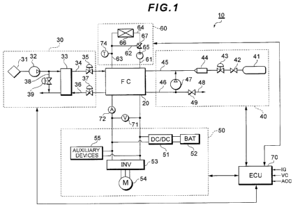
FIG. 1 shows a system constitution of a fuel cell system 10 according
to the present embodiment.
The fuel cell system 10 functions as a car-mounted power source
system mounted on a fuel cell vehicle, and includes a fuel cell stack 20 which
receives supply of a reactant gas (a fuel gas, an oxidation gas) for
generation;
an oxidation gas supply system 30 for supplying air as the oxidation gas to
the
fuel cell stack 20; a fuel gas supply system 40 for supplying a hydrogen gas
as
the fuel gas to the fuel cell stack 20; a power system 50 for controlling
charging/discharging of the power; a cooling system 60 for cooling the fuel
cell
stack 20; and a controller (ECU) 70 which controls the whole system.
The fuel cell stack 20 is a solid polymer electrolytic cell stack in which
a plurality of cells are laminated in series. In the fuel cell stack 20, an
oxidizing
reaction of formula (1) occurs in an anode pole, and a reducing reaction of
formula (2) occurs in a cathode pole. In the whole fuel cell stack 20, an
electromotive reaction of formula (3) occurs.
H2 -> 2H++2e- ... (1)
(1/2)02+2H++2e" --> H20 ... (2)
H2+(1/2)02 ->H20 ... (3)
To the fuel cell stack 20 are attached a voltage sensor 71 for detecting
an output voltage of the fuel cell stack 20 and a current sensor 72 for
detecting
CA 02663708 2009-03-13
- 7 -
a power generation current.
The oxidation gas supply system 30 has an oxidation gas passage 34
through which the oxidation gas to be supplied to the cathode pole of the fuel
cell stack 20 flows, and an oxidizing off gas passage 36 through which an
oxidizing off gas discharged from the fuel cell stack 20 flows. The oxidation
gas
passage 34 is provided with an air compressor 32 which takes the oxidation gas
from the atmosphere through a filter 31, a humidifier 33 which humidifies the
oxidation gas to be supplied to the cathode pole of the fuel cell stack 20,
and a
throttle valve 35 for regulating an amount of the oxidation gas to be
supplied.
The oxidizing off gas passage 36 is provided with a back pressure adjustment
valve 37 for regulating an oxidation gas supply pressure, and the humidifier
33
which performs water content exchange between the oxidation gas (a dry gas)
and the oxidizing off gas (a wet gas).
Between the oxidation gas passage 34 and the oxidizing off gas
passage 36 are arranged a bypass passage 38 which bypasses the fuel cell
stack 20 to connect both the passages to each other and a bypass valve 39
which regulates the flow rate of the oxidation gas flowing through the bypass
passage 38. The bypass valve 39 is usually closed, and is opened during
voltage decrease processing described later. The bypass passage 38 and the
bypass valve 39 function as bypass devices for regulating a bypass air flow
rate.
The fuel gas supply system 40 has a fuel gas supply source 41; a fuel
gas passage 45 through which the fuel gas to be supplied from the fuel gas
supply source 41 to the anode pole of the fuel cell stack 20 flows; a
circulation
passage 46 for returning, to the fuel gas passage 45, a fuel off gas
discharged
from the fuel cell stack 20; a circulation pump 47 which feeds, to the fuel
gas
CA 02663708 2009-03-13
- 8 -
passage 43, the fuel off gas under pressure in the circulation passage 46; and
a
gas/water discharge passage 48 branched from and connected to the
circulation passage 47.
The fuel gas supply source 41 is constituted of, for example, a high-
pressure hydrogen tank, a hydrogen occluded alloy or the like, and receives
the
hydrogen gas with a high pressure (e.g., 35 MPa to 70 MPa). When a block
valve 42 is opened, the fuel gas is discharged from the fuel gas supply source
41 to the fuel gas passage 45. The pressure of the fuel gas is decreased to,
for
example, about 200 kPa by a regulator 43 and an injector 44, to supply the gas
to the fuel cell stack 20.
It is to be noted that the fuel gas supply source 41 may be constituted
of a reformer which forms a hydrogen-rich reformed gas from a hydrocarbon-
based fuel, and a high-pressure gas tank which brings the reformed gas formed
by this reformer into a high-pressure state to accumulate the pressure.
The regulator 43 is a device which adjusts the upstream pressure (the
primary pressure) of the regulator into a preset secondary pressure, and is
constituted of, for example, a mechanical pressure reduction valve or the like
which decreases the primary pressure. The mechanical pressure reduction
valve has a housing provided with a back pressure chamber and a pressure
adjustment chamber formed via a diaphragm, and has a constitution in which
the primary pressure is decreased to a predetermined pressure by the back
pressure of the back pressure chamber to form the secondary pressure in the
pressure adjustment chamber.
The injector 44 is an electromagnetic driving type opening/closing
valve in which a valve body is directly driven with an electromagnetic driving
CA 02663708 2009-03-13
- 9 -
force for a predetermined driving period and detached from a valve seat,
whereby a gas flow rate or a gas pressure can be regulated. The injector 44
includes the valve seat having jet holes which jet a gas fuel such as the fuel
gas,
and also includes a nozzle body which supplies and guides the gas fuel to the
jet holes, and the valve body movably received and held in an axial direction
(a
gas flow direction) with respect to this nozzle body to open or close the jet
holes.
The gas/water discharge passage 48 is provided with a gas/water
discharge valve 49. The gas/water discharge valve 49 operates in accordance
with a command from the controller 70 to discharge, from the system, the fuel
off gas including impurities in the circulation passage 46 and a water
content.
When the gas/water discharge valve 49 is opened, the concentration of the
impurities in the fuel off gas of the circulation passage 46 lowers, and a
hydrogen concentration in the fuel off gas to be circulated through a
circulation
system can be raised.
The fuel off gas discharged through the gas/water discharge valve 49
is mixed with the oxidizing off gas flowing through the oxidizing off gas
passage
34, and diluted by a diluter (not shown). The circulation pump 47 is driven by
a
motor to circulate and supply the fuel off gas of the circulation system to
the fuel
cell stack 20.
The power system 50 includes a DC/DC converter 51, a battery 52, a
traction inverter 53, a traction motor 54 and auxiliary devices 55. The DC/DC
converter 51 has a function of raising a direct-current voltage supplied from
the
battery 52 to output the voltage to the traction inverter 53 and a function of
lowering a direct-current power generated by the fuel cell stack 20 or a
regenerative power collected by the traction motor 54 by regenerative braking
to
CA 02663708 2009-03-13
- 10 -
charge the battery 52. The charging/discharging of the battery 52 is
controlled
by these functions of the DC/DC converter 51. Moreover, an operation point
(the output voltage, an output current) of the fuel cell stack 20 is
controlled by
voltage conversion control of the DC/DC converter 51.
The battery 52 functions as a storage source of an excessive power, a
regenerative energy storage source during the regenerative braking, or an
energy buffer during load fluctuation accompanying acceleration or
deceleration
of the fuel cell vehicle. As the battery 52, for example, a nickel/cadmium
accumulator battery, a nickel/hydrogen accumulator battery, or a secondary
battery such as a lithium secondary battery is preferable.
The traction inverter 53 is, for example, a PWM inverter driven by a
pulse width modulation system, and converts the direct-current voltage output
from the fuel cell stack 20 or the battery 52 into a three-phase alternate-
current
voltage in accordance with a control instruction from the controller 70 to
control
a rotary torque of the traction motor 54. The traction motor 54 is, for
example, a
three-phase alternate-current motor, and constitutes a power source of the
fuel
cell vehicle.
The auxiliary devices 55 generically include motors arranged in units of
the fuel cell system 10 (e.g., power sources for pumps and the like),
inverters
for driving these motors, and any type of car-mounted auxiliary device (e.g.,
an
air compressor, an injector, a cooling water circulation pump, a radiator or
the
like).
The cooling system 60 includes refrigerant passages 61, 62, 63 and 64
for circulating a refrigerant through the fuel cell stack 20; a circulation
pump 65
for feeding the refrigerant under pressure; a radiator 66 for performing heat
CA 02663708 2009-03-13
- 11 -
exchange between the refrigerant and outside air; a three-way valve 67 for
switching a circulation path of the refrigerant; and a temperature sensor 74
for
detecting a refrigerant temperature. During a normal operation after
completing
a warm-up operation, the opening/closing of the three-way valve 67 is
controlled
so that the refrigerant discharged from the fuel cell stack 20 flows through
the
refrigerant passages 61, 64, is cooled by the radiator 66, and then flows
through
the refrigerant passage 63 to flow into the fuel cell stack 20 again. On the
other
hand, during the warm-up operation immediately after system startup, the
opening/closing of the three-way valve 67 is controlled so that the
refrigerant
discharged from the fuel cell stack 20 flows through the refrigerant passages
61,
62 and 63 to flow into the fuel cell stack 20 again.
The controller 70 is a computer system including a CPU, an ROM, an
RAM, an input/output interface and the like, and functions as a control device
for controlling the units (the oxidation gas supply system 30, the fuel gas
supply
system 40, the power system 50 and the cooling system 60) of the fuel cell
system 10. For example, on receiving a startup signal IG output from an
ignition switch, the controller 70 starts the operation of the fuel cell
system 10 to
obtain a demanded power of the whole system based on an accelerator open
degree signal ACC output from an accelerator sensor, a vehicle speed signal
VC output from a vehicle speed sensor and the like.
The demanded power of the whole system is a total value of a vehicle
running power and an auxiliary device power. The auxiliary device power
includes a power consumed by a car-mounted auxiliary device (the humidifier,
the air compressor, the hydrogen pump, the cooling water circulation pump or
the like), a power consumed by a device (a change gear, a wheel control
device,
CA 02663708 2009-03-13
- 12 -
a steering device, a suspension device or the like) necessary for vehicle
running,
a power consumed by a device arranged in a passenger space (an air
conditioner, a light fixture, an audio or the like) and the like.
Moreover, the controller 70 determines distribution of the output
powers of the fuel cell stack 20 and the battery 52, calculates a generation
instruction value, and controls the oxidation gas supply system 30 and the
fuel
gas supply system 40 so that the amount of the power to be generated by the
fuel cell stack 20 matches a target power. Furthermore, the controller 70
controls the DC/DC converter 51 to regulate the output voltage of the fuel
cell
stack 20, thereby controlling the operation point (the output voltage, the
output
current) of the fuel cell stack 20. To obtain the target vehicle speed
corresponding to an accelerator open degree, the controller 70 outputs, for
example, U-phase, V-phase and W-phase alternate-current voltage instruction
values as switching instructions to the traction inverter 53, and controls an
output torque and a rotation number of the traction motor 54.
FIG. 2 is an exploded perspective view of a cell 21 constituting the fuel
cell stack 20.
The cell 21 is constituted of an electrolytic film 22, an anode pole 23, a
cathode pole 24, and separators 26, 27. The anode pole 23 and the cathode
pole 24 are diffusion electrodes which sandwich the electrolytic film 22 from
both sides to constitute a sandwich structure. The separators 26, 27
constituted
of gas impermeable conductive members further sandwich this sandwich
structure from both sides, while forming the passages of the fuel gas and the
oxidation gas between the anode pole 23 and the cathode pole 24. The
separator 26 is provided with ribs 26a having recessed sections. The anode
CA 02663708 2009-03-13
- 13 -
pole 23 abuts on the ribs 26a to close openings of the ribs 26a, thereby
forming
a fuel gas passage. The separator 27 is provided with ribs 27a having recessed
sections. The cathode pole 24 abuts on the ribs 27a to close openings of the
ribs 27a, thereby forming an oxidation gas passage.
The anode pole 23 has a catalyst layer 23a including carbon powder
carrying a platinum-based metal catalyst (Pt, Pt-Fe, Pt-Cr, Pt-Ni, Pt-Ru or
the
like) as a main component, the catalyst layer coming in contact with the
electrolytic film 22; and a gas diffusion layer 23b formed on the surface of
the
catalyst layer 23a and having both gas permeability and electron conductivity.
Similarly, the cathode pole 24 has a catalyst layer 24a and a gas diffusion
layer
24b. More specifically, as to the catalyst layers 23a, 24a, the carbon powder
carrying platinum or an alloy made of platinum and another metal is dispersed
in an appropriate organic solvent, and an electrolytic solution is added as
much
as an appropriate amount, pasted and screen-printed on the electrolytic film
22.
The gas diffusion layers 23b, 24b are formed of carbon cloth woven with a
thread constituted of a carbon fiber, carbon paper or carbon felt. The
electrolytic film 22 is a proton conductive ion exchange membrane formed of a
solid polymer material, for example, a fluorine-based resin, and exerts
satisfactory electric conductivity in a wet state. The electrolytic film 22,
the
anode pole 23 and the cathode pole 24 form a membrane-electrode assembly
25.
FIG. 3 shows C-V characteristics (a cyclic voltammogram) of the fuel
cell stack 20.
The C-V characteristics show dynamic electric characteristics of the
fuel cell stack 20. When the voltage of the fuel cell stack 20 is increased at
a
CA 02663708 2009-03-13
- 14 -
fixed voltage rise ratio, a current flows in a direction from the outside to
the fuel
cell stack 20 (a minus direction). When the voltage of the fuel cell stack is
decreased at a fixed voltage drop ratio, the current flows in a direction from
the
fuel cell stack 20 to the outside (a plus direction). It has been found that
such
dynamic electric characteristics are obtained by a capacitance component
parasitically disposed in the fuel cell stack 20.
Referring to FIG. 2 again, electrons and hydrogen ions concerned with
the electrochemical reaction represented by the above formulas (1) and (2)
gather together on an interface between the electrolytic film 22 and the
catalyst
layer 23a and an interface between the electrolytic film 22 and the catalyst
layer
24a, to form an electric double layer. The voltage generated by the electrons
and hydrogen ions which have gathered together on the electric double layer is
consumed as an energy source for activating the hydrogen gas and an oxygen
gas in a ground state, respectively, and hence the voltage is generally
referred
to as an activating overvoltage. It is known that the electric double layer
formed
on the above interfaces functions as an electric energy storage source and
that
the dynamic electric characteristics of the layer are equivalent to those of a
capacitor.
When the power generation current is suddenly increased or
decreased, the lowering of an ohm voltage due to an ohm resistance of the
electrolytic film 22 follows the change of the power generation current with
good
response properties, but the activating overvoltage generated in the electric
double layer cannot follow the change of the power generation current with the
good response properties, and slowly settles into an equilibrium state over a
certain degree of time. A reason why such a difference is generated is that
the
CA 02663708 2009-03-13
- 15 -
electric characteristics of the electrolytic film 22 can be modeled as a
resistance
element, whereas the electric characteristics of the electric double layer can
be
modeled as the capacitor.
FIG. 4 is an equivalent circuit diagram in which the dynamic electric
characteristics of the fuel cell stack 20 are modeled.
The fuel cell stack 20 has a circuit constitution in which an ideal fuel
cell 28 and a capacitor 29 are connected in parallel. The ideal fuel cell 28
models a virtual fuel cell which does not have the above C-V characteristics,
and performs a behavior equivalent to that of a variable power source from a
viewpoint of the electric characteristics. The capacitor 29 models the
electric
behavior of the electric double layer formed on the above interfaces as a
capacity element. An external load 56 is an equivalent circuit which models
the
power system 50. When the current discharged from the ideal fuel cell 28 is
lfc,
the output voltage of the ideal fuel cell 28 (the output voltage of the fuel
cell
stack 20) is Vfc, the current flowing into the capacitor 29 is Ic, the current
discharged from the fuel cell stack 20 to the external load 56 is Is, the
capacity
of the capacitor 29 is C, and time is t, the following equations (4) and (5)
are
established.
Ifc = Ic+Is ... (4)
Ic = C x AVfc/At ... (5)
As shown in the equations (4) and (5), when the output voltage Vfc
rises, the current Ic flowing into the capacitor 29 increases in accordance
with a
change amount AVfc/At per unit time, and hence the current Is discharged from
the fuel cell stack 20 to the external load 56 decreases. On the other hand,
when the output voltage Vfc lowers, the current Ic flowing into the capacitor
29
CA 02663708 2009-03-13
- 16 -
decreases in accordance with the change amount OVfc/At per unit time, and
hence the current Is discharged from the fuel cell stack 20 to the external
load
56 increases. The voltage rising/lowering amount of the output voltage Vfc per
unit time can be controlled in this manner to adjust the current Is discharged
from the fuel cell stack 20 to the external load 56 (hereinafter referred to
as the
AV control for the sake of convenience).
As an application example of the AV control, there is a method for
controlling the output voltage Vfc to absorb the excessive power by the
capacitor 29, when the power generation request to the fuel cell stack 20
rapidly
decreases during, for example, the low-efficiency operation. The low-
efficiency
operation is an operation for setting an air stoichiometric ratio to a value
less
than 1.0 and controlling the amount of the reactant gas to be supplied to the
fuel
cell stack 20, to increase a power loss, thereby operating the system at a low
power generation efficiency. The air stoichiometric ratio is an oxygen surplus
ratio indicating a degree of surplus of supplied oxygen with respect to oxygen
necessary for reacting with hydrogen without any excess or deficiency. When
the air stoichiometric ratio is set to a small value to perform the low-
efficiency
operation, a concentration overvoltage becomes larger than that during the
normal operation, and hence the thermal loss (power loss) of the energy which
can be taken by a reaction between hydrogen and oxygen increases.
The low-efficiency operation is performed as, for example, means for
intentionally increasing the thermal loss during startup at a low temperature
(during the startup at a stack temperature of a predetermined temperature or
less) to quickly warm up the fuel cell stack 20, in a startup preparatory
stage
before running the vehicle or during a warm-up operation while running the
CA 02663708 2009-03-13
- 17 -
vehicle.
While holding the amount of the fuel gas to be supplied to the fuel cell
stack 20 at a fixed value and regulating the flow rate of the oxidation gas to
the
fuel cell stack 20 to obtain a desired power in accordance with an accelerator
open degree, the low-efficiency operation while running the vehicle is
performed
until the stack temperature rises to the predetermined temperature (e.g., 0
C),
and the operation is switched to the normal operation when the stack
temperature reaches the predetermined temperature.
FIG. 5 shows the I-V characteristics of the fuel cell stack 20.
During the normal operation, to improve the power generation
efficiency, the operation is controlled so that the operation point (the
output
current Ifc, the output voltage Vfc) is positioned on an I-V characteristic
curve (a
current-voltage characteristic curve) 200. On the other hand, during the low-
efficiency operation, the power generation efficiency is intentionally lowered
to
decrease the thermal loss, so that the operation point is set to a voltage
point
lower than the I-V characteristic curve 200, for example, the output voltage
Vfc
= V1. V1 is preferably, for example, about 1/2 of an open end voltage OCV of
the fuel cell stack 20. By the low-efficiency operation, since the output
voltage
Vfc is fixed to V1, the flow rate of the oxidation gas supplied from the air
compressor 32 to the fuel cell stack 20 is controlled to regulate the output
current lfc, and the power generation control is performed in accordance with
an
operation load (e.g., the accelerator open degree).
For example, the operation point at a time when the warm-up
operation is performed while running the vehicle by the low-efficiency
operation
is OP1 (I1, V1). Even when an operator turns off an accelerator to rapidly
CA 02663708 2009-03-13
- 18 -
decrease the generation instruction value for the fuel cell stack 20, the air
compressor 32 is not provided with a speed reducer such as a brake, cannot
rapidly decrease a rotation number of the compressor, and continues rotating
with a rotation number slightly larger than that matching the generation
instruction value for a while. Then, the excessive power corresponding to a
difference between the amount of the power to be generated by the fuel cell
stack 20 and the generation instruction value is generated. When the output
voltage Vfc is increased from V1 to V2 by the AV control (at this time, the
operation point moves from OP1 to OP2), the capacitor 29 parasitically present
in the fuel cell stack 20 can be charged with this excessive power, so that
the
power value supplied from the fuel cell stack 20 to the external load 56 can
substantially match the generation instruction value.
After charging the capacitor 29 with the excessive power, the output
voltage Vfc is decreased from V2 to V1 to return the operation point from OP2
to OP1. At this time, the power of the charged capacitor 29 is discharged to
the
external load 56 with the drop of the output voltage Vfc, whereby the power
generation of the fuel cell stack 20 needs to be suppressed so that the power
supplied from the fuel cell stack 20 to the external load 56 (the sum of the
power generated by the fuel cell stack 20 and the power discharged from the
capacitor 29) matches the power demanded by the external load 56.
To solve the problem, the supply of the oxidation gas from the air
compressor 32 to the fuel cell stack 20 is decreased to a stable limit flow
rate
(the minimum flow rate with which the air can be supplied in such a range
capable of securing flow rate stability or response properties in a low
rotation
region), and further the valve open degree of the bypass valve 39 is regulated
CA 02663708 2009-03-13
- 19 -
to reduce the supply of the oxidation gas to the fuel cell stack 20 to the
stable
limit flow rate or less.
In a case where the capacity of the air compressor 32 is a large
capacity, it is difficult to reduce the flow rate of the oxidation gas
supplied to the
fuel cell stack 20 to the stable limit flow rate or less so that the power
supplied
from the fuel cell stack 20 to the external load 56 during the voltage
decrease
processing matches the power demanded by the external load 56, but
according to the above constitution, the flow rate of the bypass air flowing
through the bypass passage 38 can be regulated to reduce the flow rate of the
oxidation gas supplied to the fuel cell stack 20 to the stable limit flow rate
or less.
After completing the voltage decrease processing, the rotation number
of the air compressor 32 and the valve open degree of the bypass valve 39 are
regulated so as to supply the oxidation gas matching the demanded power to
the fuel cell stack 20. When the capacity of the air compressor 32 is a large
capacity and the air compressor 32 is driven for a purpose of the generation
of
the power matching the demanded power after completing the voltage decrease
processing, the oxidation gas more than necessary is supplied to the fuel cell
stack 20, and the excessive power might be generated. However, according to
the above constitution, in addition to the driving control of the air
compressor 32,
the flow rate of the bypass air flowing through the bypass passage 38 can be
regulated to stably supply the oxidation gas matching the demanded power to
the fuel cell stack 20.
It is to be noted that in a case where the air compressor 32 has a small
capacity, the flow rate of the air supplied to the fuel cell stack 20 can
minutely
be regulated so that the power supplied from the fuel cell stack 20 to the
CA 02663708 2009-03-13
- 20 -
external load 56 during the voltage decrease processing matches the power
demanded by the external load 56 and the oxidation gas matching the
demanded power can stably be supplied to the fuel cell stack 20 after
completing the voltage decrease processing, the bypass passage 38 is not
required. Further in such a case, the driving of the air compressor 32 may be
stopped during the voltage decrease processing.
It is to be noted that an operation point OP3 (I1, V3) positioned on the
I-V characteristic curve 200 indicates that the maximum voltage which can
theoretically be output from the fuel cell stack 20 at the output current 11
is V3.
A range in which the output voltage Vfc can be increased by the AV control
while keeping the output current Ifc at 11 during the low-efficiency operation
at
the operation point OP1 is limited to a range of OP1 to OP3. Therefore, when a
voltage rise in excess of (V3-V1) is instructed, the operation point of the I-
V
characteristic curve 200 corresponding to the instructed voltage value is a
new
operation point.
FIG. 6 is a timing chart showing a control process of the AV control.
As an example in which the power generation request for the fuel cell
stack 20 rapidly decreases, there will be assumed a case where a state in
which the accelerator is on is kept for a period from time t10 to time t11 and
the
accelerator turns off at the time t11, and the AV control will be described.
At the time t11 when the accelerator turns off, the operation load of the
fuel cell stack 20 (specifically, the power required for the vehicle running)
decreases, and hence the controller 70 calculates a generation instruction
value
Pref so as to generate the power matching the decrease of the operation load.
At this time, the power to be supplied to car-mounted auxiliary devices may be
CA 02663708 2009-03-13
- 21 -
generated, and hence the generation instruction value Pref gradually
decreases.
The operation point at the time t11 is OP1 (I1, V1).
However, since the air compressor 32 is not provided with a speed
reducer such as the brake, the rotation of the air compressor cannot
immediately be restricted even when the accelerator turns off at the time t11,
the air compressor inertially continues rotating for a while, and the amount
of
the oxidation gas larger than the oxidation gas supply amount matching the
generation instruction value Pref is supplied to the fuel cell stack 20.
Therefore,
a generation amount Pmes of the fuel cell stack 20 becomes larger than the
generation instruction value Pref, and a difference Ws between the generation
amount and the generation instruction value is the excessive power.
The DC/DC converter 51 increases the output voltage Vfc of the fuel
cell stack 20 as much as AVfc =(V2-V1), and sets the operation point to OP2
(I1, V2). Then, the capacitance component in the fuel cell stack 20, that is,
the
capacitor 29 is charged with the excessive power Ws, and hence a power
(Pmes-Ws) output from the fuel cell stack 20 substantially matches the
generation instruction value Pref.
At time t12 when the charging of the capacitor 29 with the excessive
power Ws is completed, the output voltage Vfc is decreased as much as AVfc =
(V2-V1), and the operation point returns from OP2 (I1, V2) to OP1 (I1, V1). At
this time, the supply of the oxidation gas from the air compressor 32 to the
fuel
cell stack 20 is decreased to the stable limit flow rate, and the valve open
degree of the bypass valve 39 is further regulated to suppress the power
generation of the fuel cell stack 20. When the air compressor 32 has a small
capacity and the oxidation gas matching the demanded power can stably be
CA 02663708 2009-03-13
- 22 -
supplied to the fuel cell stack 20 after completing the voltage decrease
processing, the rotation of the air compressor 32 may be stopped during the
voltage decrease processing. After the operation point returns to OP1, the
rotation number of the air compressor 32 is controlled so as to supply the
oxidation gas matching the demanded power to the fuel cell stack 20.
It is to be noted that as one example of the voltage decrease
processing, processing of decreasing the output voltage Vfc increased so as to
absorb the excessive power Ws has been illustrated, but in addition, the above
control can be applied even to, for example, a case where during the startup
at
the low temperature, the output voltage Vfc is decreased from the open end
voltage OCV to the voltage value of a desired operation point to perform the
low-efficiency operation.
As described above, when the supply of the oxidation gas to the fuel
cell stack 20 is decreased in consideration of the discharge from the
capacitor
29 to the external load 56 when decreasing the output voltage Vfc of the fuel
cell stack 20, the power supplied from the fuel cell stack 20 to the external
load
56 can match the power demanded by the external load 56.
In the above embodiment, a utilizing configuration in which the fuel cell
system 10 is used as the car-mounted power source system has been
illustrated, but the utilizing configuration of the fuel cell system 10 is not
limited
to this example. For example, the fuel cell system 10 may be mounted as a
power source of a mobile body (a robot, a ship, an airplane or the like) other
than the fuel cell vehicle. Moreover, the fuel cell system 10 according to the
present embodiment may be used as a power generation facility (a stational
power generation system) of a housing, a building or the like.
CA 02663708 2009-03-13
- 23 -
Industrial Applicability
According to the present invention, a cell operation can be controlled in
consideration of discharge from a capacitance component of a fuel cell to an
external load when decreasing the output voltage of the fuel cell.