Note: Descriptions are shown in the official language in which they were submitted.
CA 02663837 2009-04-23
l
LOW PROFILE CLEANING DEVICE WITH PIVOTING HANDLE
CROSS REFERENCE TO RELATED APPLICATION
[0001] This application claims the benefit of U.S. Provisional Application
61/125,239, which was filed on April 23, 2008, the entire disclosure of which
is
hereby incorporated by reference.
BACKGROUND OF THE INVENTION
1. Field of the Invention
[0002] The present invention pertains to a cleaning device. More
particularly, the present invention pertains to a cleaning device having a
pivoting joint provided on the handle. Even more particularly, the present
invention pertains to a cleaning device having a pivoting joint provided on
the
handle and having a wheel rotatably secured to the joint to facilitate the
cleaning
of otherwise hard to reach places.
2. Description of the Prior Art
[0003] Cleaning devices having pivotable heads are well-known in the
prior art, such as those found in U.S. Patent Nos. 5,414,889 to Sartori and
3,704,479 to Whitaker. Cleaning heads which are angle-adjustable relative to
the arm or handle of the cleaning device allow the user to reach and clean
surfaces from a variety of angles and positions which would otherwise be
unobtainable with a cleaning device having a fixed head.
[0004] It is well known in the art to provide a cleaning device with an
extendable or telescoping arm, such as found in U.S. Patent No. 4,794,663 to
Vosbikian. Telescoping arms allow the user of the cleaning device to clean
remote locations that would be otherwise unreachable.
1
CA 02663837 2009-04-23
[0005] However, there are other locations that conventional cleaning
devices cannot reach without the user exerting an excessive amount of effort.
For instance, cleaning surfaces under objects which are large and low, e.g.,
furniture and appliances. Cleaning under these objects often requires the
object
to be moved before cleaning the surface. Because of this, surfaces below
objects
such as sofas or refrigerators are seldom cleaned due to the excessive effort
required to move objects that are so large.
[0006] Therefore, a need remains for a cleaning device which can reach
under low objects without requiring excessive effort by the cleaning device's
user.
[0007] The present invention, as is detailed hereinbelow, seeks to resolve
this issue by providing a cleaning device with a pivoting joint on the arm and
having at least one wheel rotatably secured to the joint.
SUMMARY OF THE INVENTION
[0008] The present invention provides a cleaning device having a pivoting
joint provided on a telescoping arm, and which generally comprises:
(a) a head assembly having an upper surface and a lower surface,
the upper surface having a bracket, and the lower surface having a cleaning
attachment secured thereto;
(b) an elongated lower arm having a first end and a second end;
(c) a pivotable head connector for pivotably connecting the lower
arm to the head assembly, the pivotable head connector having a head portion
and an arm portion, the head portion being rotatably secured to the head
assembly along a first axis, the head portion being rotatably secured to the
arm
2
CA 02663837 2009-04-23
portion along a second axis, and the arm portion being secured to the first
end of
the lower arm;
(d) an elongated upper arm having a first end and a second end; and
(e) a pivotable joint having a male connector and a female connector
which are rotatably secured to each other, the female connector having a pair
of
spaced apart parallel tabs, the male connector being disposed between the pair
of
tabs, the male connector and female connector being dimensioned for close
interfitment with each other, the male connector being secured to the second
end
of the lower arm, and the female connector being secured to the first end of
the
upper arm.
[0009] The cleaning device may also include at least one wheel rotatably
secured to the pivotable joint for facilitating translation of the joint along
a
cleaning surface.
[0010] The cleaning device may further include a telescoping arm which is
slidably insertable in the upper arm and may be locked in either a retracted
or
extended position.
[0011] For a more complete understanding of the present invention,
reference is made to the following detailed description and accompanying
drawing. In the drawing, like reference characters refer to like parts
throughout
the views in which:
BRIEF DESCRIPTION OF THE DRAWINGS
[0012] FIG. 1 is a side view of a preferred embodiment of the present
invention hereof
3
CA 02663837 2009-04-23
[0013] FIG. 2 is an enlarged exploded view showing the head assembly, the
lower arm, and the pivotable head connector;
[0014] FIG. 3 is an enlarged view showing the telescoping arm in an
extended position;
[0015] FIG. 4 is an enlarged exploded view of the pivotable joint;
[0016] FIG. 5 is a perspective view of the present invention configured for
cleaning below low objects, with the pivotable joint rotated about its axis of
rotation such that the upper and lower arms are misaligned, and the
telescoping
arm is in the extended position;
[0017] FIG. 6 is a perspective view of the present invention configured for
conventional cleaning, with the upper and lower arms being substantially
axially
aligned and the telescoping joint in the retracted position; and
[0018] FIG. 7 is an enlarged view of the head assembly showing
attachment slots for securing a cleaning attachment.
DETAILED DESCRIPTION OF THE PREFERRED EMBODIMENT
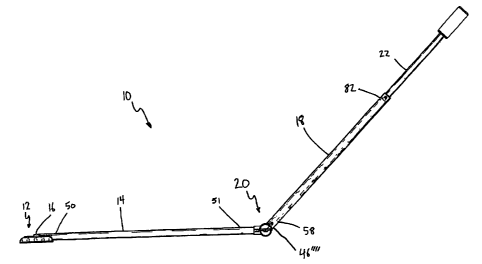
[0019] In accordance with the present invention and as shown generally in
FIGS. 1, 5, and 6, there is provided a cleaning device 10 having a head
assembly
12 pivotably connected to a lower arm 14 via a pivotable head connector 16. An
upper arm 18 is pivotably connected to the lower arm 14 by a pivotable joint
20,
and a telescoping arm 22 is slidably retained within the upper arm 18. The
lower arm 14, upper arm 18, and telescoping arm 22 are elongated and tubular
in shape.
[0020] As shown in FIGS. 2 and 7, the head assembly 12 is generally
rectangular in shape and has an upper surface 24 and a lower surface 26. A
4
CA 02663837 2009-04-23
cleaning attachment 28 is secured to the lower surface 26. The cleaning
attachment 28 may comprise any type of suitable cleaner that is known to one
having ordinary skill in the art, such as bristles, textured cloths, rotatable
brushes, vacuum, or the like.
[0021] Preferably, the cleaning attachment 28 is a removable disposable
textured cloth. In this preferred embodiment, the cleaning attachment 28 is
removably secured to the head assembly 12 by a plurality of gripping slots 30.
The plurality of gripping slots 30 are of the type disclosed in U.S. Patent
Publication No. 2007/0256266 to Michelson et al., the disclosure of which is
herein incorporated by reference.
[0022] The head assembly 12 includes a bracket 32 which is fixed to the
upper surface 24. The bracket 32 is provided for attaching the pivotable head
connector 16 to the head assembly 12 as described below. The bracket 32 is
located substantially proximal to the center of mass of the head assembly 12.
The bracket 32 has a pair of spaced apart opposed bracket tabs 34,34' which
extend upwardly from the upper surface 24 along the z-axis, as shown in FIG.
2.
The bracket tabs 34,34' are aligned parallel to each other, and each tab
34,34' is
provided with a hole 36,36' which extends through the respective tabs 34,34',
the
holes 36,36' being coaxially aligned along the yaxis. Each of the bracket tabs
34,34' has an inclined surface 35,35', respectively, for receiving a detent
44,44',
respectively, as discussed below.
[0023] The pivotable head connector 16 is provided for pivotally connecting
the head assembly 12 to the lower arm 14, thus enabling pivotal movement of
the head assembly 12 relative to the lower arm 14. The pivotable head
connector
CA 02663837 2009-04-23
16 has a head portion 38 and an arm portion 40. The head portion 38 has a
first
end 39 and a second end 41, the first end 39 having a pair of opposed faces
42,42'
which are oriented along the x-z plane. Each of the opposed faces 42,42' has
an
associated cylindrically-shaped detent 44,44' extending outwardly therefrom
along the yaxis.
[0024] The head portion 38 and detents 44,44' are dimensioned such that
the detents 44,44' are insertable into, and retained by, the holes 36,36',
forming a
snap connection 46. The detents 44,44', holes 36,36', and inclined surfaces
35,35'
are dimensioned such that the detents 44,44' are inserted between the tabs
34,34' and against the inclined surfaces 35,35'. The head portion 38 is forced
downwardly between the tabs 34,34'. The inclined surfaces 35,35' form an
increasingly tight interface against the detents 44,44' as the head portion 38
is
inserted between the tabs 34,34'. The tabs 34,34' elastically deflect away
from
the head portion 38 as a result of the abutting force with the detents 44,44'.
As
the detents 44,44' are forced downwardly, they snap into their corresponding
holes 36,36', thus rotatably securing the detents 44,44' within the respective
holes 36,36' and allowing the head portion 38 and the head assembly 12 to
pivot
with respect to each other along the y-axis.
[0025] As is noted below, additional snap connections 46,46'46", etc. are
used to connect various elements of the cleaning device 10 together.
[0026] The second end 41 of the head portion 38 comprises a head portion
tab 45. The head portion tab 42 includes a second pair of opposed faces 49,49'
having a hole 47 extending therethrough.
6
CA 02663837 2009-04-23
[0027] The arm portion 40 of the pivotable head connector 16 includes a
pair of spaced apart opposed tabs 48,48', each tab having a detent 44",44"'.
The
tabs 48,48', detents 44",44"', and the hole 47 form a second snap connection
46',
which is assembled and used in the manner described above with reference to
the snap connection 46.
[0028] The lower arm 14 has a first end 50 and a second end 51, the first
end 50 being connected to the arm portion 40 of the pivotable head connector
16
by a third snap connection, 46", such as shown in FIGS. 2 and 7. The lower arm
.14 may have a planar surface 52 extending therealong to assist in sliding the
lower arm 14 along the floor when in use.
[0029] As shown in detail in FIG. 4, the pivotable joint 20 is provided to
enable relative rotation between the lower arm 14 and the upper arm 18. The
pivotable joint 20 includes a male connector 54 and a female connector 56. A
fourth snap connection 46"' connects the male connector 54 to the second end
51
of the lower arm 14. The upper arm 18 has a first end 58 which is connected to
the female connector 56 by a fifth snap connection 46"".
[0030] The female connector 56 has a pair of spaced apart parallel tabs
60,60'. Each of the tabs 60,60' have a pair of opposed faces 62,62', and
62",62"',
respectively, the opposed faces 62,62',62",62"' being parallel to the x
zplane. The
faces 62',62" have a recessed track 64,64' and an inclined surface 35",35"'.
Each
recessed track 64,64' is generally "J"-shaped, having a linear portion and a
curved portion. The inclined surfaces 35",35"' each extend from the outer edge
of
the respective tab 60,60' to the respective recessed track 64,64'.
7
CA 02663837 2009-04-23
[0031] The male connector 54 comprises a cylindrical portion 68 having a
pair of opposed planar circular faces 70,70'. The cylindrical portion 68 is
oriented coaxially along the ,yyaxis such that the opposed circular faces
70,70' are
oriented in the x-z plane. Each face of the pair of faces 70,70' includes a
concentrically-located center joint detent 72,72' and an offset joint detent
74,74'.
The tabs 60,60' from the female connector 56 and the cylindrical portion 68
from
the male connector 54 are dimensioned for close interfitment between the
cylindrical portion 68 and the tabs 60,60'.
[0032] During assembly of the cleaning device 10, the center joint detents
72,72' and their respective offset joint detents 74,74' are aligned with a
respective one of the inclined surfaces 35",35"'. The male and female
connectors,
54 and 56, respectively, are assembled together in the manner described above
with reference to the snap connection 46, such that the detents 72,72' and
74,74'
are pressed through their respective inclined surface 35",35"' and into their
respective recessed track 64,64'. Each of the center joint detents 72,72' are
rotatably secured to a respective one of the recessed tracks 64,64'. The
offset
joint detents 74,74' are slidable within the curved portion of the respective
recessed track 64,64', and the male and female connectors, 54 and 56, rotate
about the center joint detents 72,72'. The male and female connectors, 54 and
56, are capable of rotating ninety degrees with respect to each other.
[0033] There is also provided at least one wheel 76, and preferably, at least
a pair of wheels 76,76'. Each of the wheels 76,76' has a pair of
concentrically-
located axial hubs 78,78', which are integrally formed with the respective
wheels
76,76' and serve as an axle for rotation for their respective one of the
wheels
8
CA 02663837 2009-04-23
76,76'. Each of the wheels 76,76' are retained in a wheel housing 80,80' in
the
manner described above with reference to the snap connection 46. The hubs
78,78' are each secured within a respective hole (not shown) in the respective
wheel housing 80,80'.
[0034] A second end 82 of the upper arm 18 is shown in detail in FIG. 3.
As noted above, the upper arm 18 includes a telescoping arm 22. The
telescoping
arm 22 is slidably disposed within the second end 82 of the tubular upper arm
18. The telescoping arm 22 preferably has a grip 84 of the type which is well
known in the art, such as found in U.S. Patent No. 2,210,724 to Leathers. The
grip 84 may be formed from any suitable type of material, such are rubber,
nylon, or the like.
[0035] A sixth and seventh snap connections, 46""' and 46""" are provided
for locking the telescoping arm 22 into retracted and extended positions.
Alternatively, at least one hole (not shown) may be formed on the upper arm 18
and the telescoping arm 22 may include at least a pair of spring-loaded
locking
pins (not shown). The spring-loaded locking pins may be of the type as
disclosed
in U.S. Patent Publication No. 2008/0000137 to Lee, and are used to adjustably
position the telescoping arm 22. Alternatively, screw-based means for locking,
such as found in U.S. Patent No. 4,794,663 to Vosbikian may be used to lock
the
telescoping arm 22 in position relative to the upper arm 18. The disclosures
of
U.S. Patent Publication No. 208/0000137 and U.S. Patent No. 4,794,663 are
hereby incorporated by reference.
[0036] In operation, the cleaning device 10 can be used in a manner typical
of conventional cleaning devices, or it may be converted for low profile use
in
9
. . . . . . . . . i
CA 02663837 2009-04-23
cleaning low locations. In conventional operation, the telescoping arm 22, if
provided, is locked into the retracted position with respect to the upper arm
18.
[0037] In addition, the pivotable joint 20 is also secured in a position
whereby the lower arm 14 and upper arm 18 are oriented coaxial to each other.
The pivotable joint 22 may be secured into a one hundred and eighty degree
position by the user of the cleaning device 10 by rotating the cleaning device
10
one hundred and eighty degrees about the axis of the upper and lower arms
14,18. In typical use, the user positions the arms 14,18 of the cleaning
device 10
at an angle of about forty-five degrees relative to the floor. The user
applies
downward pressure on the cleaning device 10 to clean the floor. The downward
pressure is transferred to the pivotable joint 22, wherein the offset joint
detents
74,74', being secured within a respective one of the recessed tracks 64,64',
are
pressed against the far ends of the recessed tracks 64,64'. Contact between
the
offset joint detents 74,74' and the end of each of the recessed tracks 64,64'
resist
rotation of the pivotable joint 22 past one hundred and eighty degrees.
[0038] The cleaning device 10 can be converted to its low profile
configuration by rotating the cleaning device 10 one hundred and eighty
degrees
about the axis of the arms 14,18.
[0039] Furthermore, the telescoping arm 22 is then extended from its
retracted position. Extending the telescoping arm 22, if provided, allows the
user to operate the cleaning device 10 from the same height, regardless of
whether the cleaning device 10 is configured for conventional cleaning or low
profile cleaning.
CA 02663837 2009-04-23
[0040] Lastly, the wheels 76,76' allow the pivotable joint 20 to roll along
the floor while the cleaning device 10 is in a low profile configuration. The
wheels 76,76' assist in transferring force applied by the user to the cleaning
surface. The wheels 76,76' also serve to protect the integrity of both the
pivotable joint 20 and the floor by reducing friction therebetween.
[0041] The components of the cleaning device 10, including the head
assembly 12, the lower arm 14, the pivotable head connector 16, the upper arm
18, the pivotable joint 20, and the telescoping arm 22 may all be formed from
suitable materials known to one of ordinary skill in the art, including metal,
wood, or polymers. Preferably the components of the cleaning device 10 are all
formed from like materials. Even more preferably, the components of the
cleaning device 10 are formed from a suitable polymer, such as HDPE, ABS,
nylon, a fiber-reinforced polymer such as fiberglass, or the like.
[0042] It is to be understood by one of ordinary skill in the art that the
present invention is not limited to the specific aspects described above. For
instance, the wheels may be replaced by other means for reducing friction
between the pivotable joint and the floor, such as a pad having a surface with
a
low coefficient of friction.
[0043] In addition, although not shown in the drawing, the pivotable joint
22 may comprise a ball and socket assembly or other suitable means for bending
the arms rotatable in all axes, i.e., three-hundred and - sixty degrees. Also,
a
cleaning fluid dispenser may be associated with the device for hard floor or
carpet cleaning or the like.
11
CA 02663837 2009-04-23
[0044] As is apparent from the preceding, the present invention provides a
cleaning device such as a vacuum, hand sweeper, mop, broom, or the like, with
a
pivoting joint on the arm and having a wheel rotatably secured to the joint.
The
pivoting joint and overall low profile design allows the cleaning device to
clean
surfaces under low objects which would otherwise require repositioning of the
object. There is also provided a wheel on the pivoting joint which both
assists in
using the cleaning device, and protects the integrity of the pivoting joint
and the
floor. A.telescoping arm may be provided to assist the user in cleaning when
the
cleaning device is configured for cleaning under low objects.
[0045] What is claimed is:
12