Note: Descriptions are shown in the official language in which they were submitted.
CA 02664103 2009-03-20
WO 2008/036618 PCT/US2007/078703
AUTOMATIC HEADING CONTROL SYSTEM FOR
TILTROTOR AIRCRAFT AND HELICOPTERS
BACKGROUND OF THE INVENTION
FIELD OF THE INVENTION
[0001] Embodiments of the present invention relate to systems and methods for
automatically controlling the heading of a tiltrotor aircraft or helicopter
experiencing an excessive lateral force. More particularly, embodiments of the
present invention relate to systems and methods for automatically commanding a
heading change of a tiltrotor aircraft or helicopter when a lateral swashplate
position signal or a lateral acceleration signal exceeds a preset limit.
BACKGROUND INFORMATION
[0002] Rotorcraft can include, but are not limited to, tiltrotor aircraft,
helicopters,
or autogyros. Rotorcraft can be manned or unmanned aircraft. Manned rotorcraft
can be commanded by a pilot. Unmanned rotorcraft can be commanded by a
ground control station (GCS) operator or flight control box (FCB) operator.
Rotorcraft can, for example, take off and land vertically, move horizontally,
or
hover in place. Rotorcraft can also generally move or maintain their position
in
response to external forces by pitching one or more main rotors.
[0003] The control systems for rotorcraft are complex electrical and/or
mechanical systems. The control systems respond to the pilot or operator's
input,
but also must accommodate forces acting upon rotor assemblies that are
generally
outside the control of the pilot or operator. Mechanical control systems
typically
include a swashplate arrangement that includes a stationary portion and a
rotating
portion. Typically, the lower, stationary portion is fixed in position and
will not
rotate, but has the ability to move up and down and/or tilt in any given
direction.
1
CA 02664103 2009-03-20
WO 2008/036618 PCT/US2007/078703
This is commonly referred to as the "stationary" or "non-rotating" swashplate.
Pilot or operator inputs alter the vertical position of the stationary
swashplate
through the collective control and the tilt or pitch of the stationary
swashplate
through the cyclic control. The rotating portion of the swashplate arrangement
is
free to rotate. Of course, pilot or operator inputs to the non-rotating
portion are
passed through to the rotating portion of the control systems.
[0004] Excessive external lateral force can adversely affect the control
system of
a rotorcraft. Such an excessive external lateral force can include, but is not
limited to, a large cross wind (normal to the aircraft heading) experienced by
a
rotorcraft during hover or landing. Generally, a pilot or operator will
command
the control system of the rotorcraft to handle the lateral force or cross wind
once it
is detected. The control system will then tilt the swashplate to oppose the
lateral
force.
[0005] For a tiltrotor aircraft, there are two methods of controlling the
lateral
velocity and position of the aircraft while hovering with a cross wind. The
first
method requires tilting the aircraft downward in the lateral axis toward the
cross
wind. This method requires no lateral cyclic swashplate input, but rather
relies
upon controlling the differential collective rotor control to hold the lateral
aircraft
attitude at the required position to yield the desired lateral force to oppose
the
cross wind. The second method allows the aircraft to hover with a lateral
attitude
of zero by using the lateral swashplate control to produce the lateral force
to
oppose the cross wind, while the differential collective control is used to
maintain
the aircraft level attitude. The second method provides dynamic and
operational
advantages, but this type of opposition to the lateral force can present at
least two
additional problems. First, the lateral force can be so large that it exceeds
the
2
CA 02664103 2009-03-20
WO 2008/036618 PCT/US2007/078703
physical limitations of the control system and swashplate. Second, so much of
the
control system or tilt in the swashplate is used to oppose the lateral force
that there
is not enough control left in the control system to fly or land the
rotorcraft.
[0006] In view of the foregoing, it can be appreciated that a need exists for
systems and methods that can monitor the lateral forces on a rotorcraft and
automatically change the heading of the rotorcraft if it experiences an
excessive
lateral force..
BRIEF SUMMARY OF THE INVENTION
[0007] One embodiment of the present invention is a method for automatically
reducing the effect of a component of an external force that is laterally
incident on
a rotorcraft. A signal of the rotorcraft indicative of and proportional to the
component is monitored. An absolute value of the signal and a preset high
limit
are compared. If the absolute value is greater than or equal to the preset
high
limit, manual heading control of the rotorcraft is disabled and the heading of
the
rotorcraft is adjusted with respect to the external force so as to decrease
the lateral
component of the external force experienced by the rotorcraft.
[0008] Another embodiment of the present invention is a method for
automatically controlling the heading of a rotorcraft. A lateral control
signal of
the rotorcraft is monitored. An absolute value of the lateral control signal
is
compared to a preset high limit. If the absolute value of the control signal
is
greater than or equal to the preset high limit, a lateral heading command that
will
decrease the absolute value of the lateral control signal is calculated from
the
lateral control signal, a heading error is calculated from a difference
between the
lateral heading command and a current heading of the rotorcraft, a manual
3
CA 02664103 2009-03-20
WO 2008/036618 PCT/US2007/078703
heading command is disabled, and the heading error is provided to a flight
control
system of the rotorcraft to control the heading of the rotorcraft.
[0009] Another embodiment of the present invention is a system for
automatically
controlling the heading of a rotorcraft. The system includes a data capture
module, a comparison module, and a heading control module. The data capture
module monitors a lateral control signal of the rotorcraft. The comparison
module
accepts the lateral control signal as input from the data capture module and
compares an absolute value of the lateral control signal to a preset high
limit. The
heading control module accepts the lateral control signal as input from the
data
capture module and a result of the comparison of the absolute value of the
lateral
control signal to a preset high limit as input from the comparison module. The
heading control module calculates a lateral heading command from the lateral
control signal that will decrease the absolute value, calculates a heading
error
from a difference between the lateral heading command and a current heading of
the rotorcraft, disables a manual heading command, and provides the heading
error to a flight control system of the rotorcraft to control the heading of
the
rotorcraft, if the result from the comparison module identifies the absolute
value
as greater than or equal to the preset high limit.
BRIEF DESCRIPTION OF THE DRAWINGS
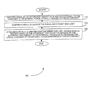
[0010] Figure 1 is a flowchart showing a method for automatically reducing the
effect of a component of an external force that is laterally incident on a
rotorcraft,
in accordance with an embodiment of the present invention.
[0011] Figure 2 is a flowchart showing a method for automatically controlling
the
heading of a rotorcraft, in accordance with an embodiment of the present
invention.
4
CA 02664103 2009-03-20
WO 2008/036618 PCT/US2007/078703
[0012] Figure 3 is a schematic diagram of a system for automatically
controlling
the heading of a rotorcraft, in accordance with an embodiment of the present
invention.
[0013] Before one or more embodiments of the invention are described in
detail,
one skilled in the art will appreciate that the invention is not limited in
its
application to the details of construction, the arrangemerits of components,
and the
arrangement of steps set forth in the following detailed description or
illustrated in
the drawings. The invention is capable of other embodiments and of being
practiced or being carried out in various ways. Also, it is to be understood
that the
phraseology and terminology used herein is for the purpose of description and
should not be regarded as limiting.
DETAILED DESCRIPTION OF THE INVENTION
[0014] Generally, a pilot or operator commands the heading of a rotorcraft for
flight conditions at or near hover conditions. If there is not enough control
authority for the desired flight condition, then it is the responsibility of
the pilot or
operator to determine when the limits of the control authority are being
approached and to avoid commands that will exceed the limits. If a command
exceeds the limits of the control authority, the rotorcraft will not be able
to follow
the command.
[0015] In one embodiment of the present invention, the heading of a rotorcraft
is
controlled automatically in flight conditions where it might not be possible
for the
rotorcraft to follow specific heading commands. Such flight conditions can
include, for example, hovering in high wind where the range of heading control
is
severely limited.
CA 02664103 2009-03-20
WO 2008/036618 PCT/US2007/078703
[0016] When a lateral force is generated by using lateral cyclic blade pitch
to
resist a cross wind, there is a limit to the control authority available.
Lateral
cyclic blade pitch is produced, for example, by lateral swashplate tilt. As
more
lateral cyclic blade pitch is required to oppose the lateral wind force, there
is less
longitudinal cyclic blade pitch available. If the control limits are not
closely
observed, a loss of control can result. Automatically controlling the heading
of a
rotorcraft can prevent the loss of control that can occur if the control
authority
needed for the flight condition is greater than the amount that is available.
[0017] In the case of a tiltrotor, there is an additional pitch moment
generated by a
cross wind or side slip, which requires more longitudinal swashplate authority
to
correct for this condition. The increased longitudinal cyclic blade, pitch
required
can cause conditions where there is not enough control authority to fly the
aircraft.
[0018] In another embodiment of the present invention, a system detects when
the
lateral swashplate position exceeds a preset level and a yaw command is
generated
to turn the aircraft into the wind and reduce the amount of total swashplate
command required. This automatic heading correction is triggered when the
filtered lateral swashplate position exceeds the preset level or safe
condition and is
turned off when the filtered lateral swashplate position falls within a safe
range.
[0019] In another embodiment of the present invention, lateral acceleration is
used as the signal to command the automatic heading control. If lateral cyclic
blade pitch is used for lateral control, then the rotorcraft can attain
lateral
velocities or hover in a cross wind while maintaining a level roll attitude.
Some
rotorcraft do not use lateral swashplate commands to generate lateral forces,
however. When lateral cyclic blade pitch is not used for lateral control, the
6
CA 02664103 2009-03-20
WO 2008/036618 PCT/US2007/078703
automatic heading system uses lateral acceleration as the signal to command
the
automatic heading control.
[0020] In this embodiment, there is a steady lateral acceleration caused by
the roll
attitude of the rotorcraft. This lateral acceleration is an indication of the
side force
or lateral force required to maintain the flight condition. A system detects
when
the lateral acceleration exceeds a preset level and a yaw command is generated
to
turn the aircraft into the wind and reduce the amount of roll of the
rotorcraft. This
automatic heading correction is triggered when the lateral acceleration
exceeds the
preset level or safe condition and is turned off when the lateral acceleration
falls
within a safe range.
[0021] The heading of a manned rotorcraft is typically commanded by a pilot.
The heading of an unmanned rotorcraft can be commanded by a GCS operator or
FCB operator. Automatically controlling the heading of a rotorcraft in
response to
lateral external forces is particularly important for unmanned rotorcraft,
where
these is no pilot onboard to detect an unsafe condition.
[0022] In another embodiment of the present invention, both the lateral
swashplate position and the lateral acceleration signal are available to
command
the automatic heading control. An automatic heading control system uses the
lateral swashplate position or the lateral acceleration signal to limit the
lateral
forces to safe levels by automatically commanding a heading change to reduce
the
force required to oppose the lateral forces. The automatic heading control
system
operates the same whether a lateral swashplate command or a roll attitude
command is used as the lateral control device. Safe operating levels are
determined and preset values are established for triggering the automatic
heading
control system to engage and disengage. When the preset high limit is
exceeded,
7
CA 02664103 2009-03-20
WO 2008/036618 PCT/US2007/078703
the rotorcraft heading is commanded to change in the direction to reduce the
amount of lateral swashplate tilt or lateral acceleration. The heading stops
changing when the signal is reduced below a preset low limit.
[0023] The preset values are set based upon the control authorities available
and
the level of lateral and longitudinal commands that are required for safe
flight.
The preset values of swashplate tilt are, for example, based upon a short term
average of the commands. A short term average of commands is obtained using a
two second time constant low-pass filter, for example. The filtering of
signals
prevents automatic heading commands from being triggered for very short
commands, when average signals are not excessive. .
[0024] Figure 1 is a flowchart showing a method 100 for automatically reducing
the effect of a component of an external force that is laterally incident on a
rotorcraft, in accordance with an embodiment of the present invention. The
external force can be, but is not limited to, a cross wind.
[0025] In step 110 of method 100, a signal of the rotorcraft indicative of and
proportional to the component is monitored. The signal can be, but is not
limited
to, a lateral swashplate position signal or a lateral acceleration signal.
[0026] In step 120, an absolute value of the signal and a preset high limit
are
compared.
[0027] In step 130, if the absolute value is greater than the preset high
limit,
manual heading control of the rotorcraft is disabled and the heading of the
rotorcraft is adjusted with respect to the external force so as to decrease
the lateral
component of the external force experienced by the rotorcraft.
[0028] In another embodiment of method 100, if the absolute value of the
signal is
less than a preset low limit, manual control of the rotorcraft is enabled.
8
CA 02664103 2009-03-20
WO 2008/036618 PCT/US2007/078703
[0029] Figure 2 is a flowchart showing a method 200 for automatically
controlling the heading of a rotorcraft, in accordance with an embodiment of
the
present invention. The rotorcraft can be a manned vehicle or an unmanned
vehicle.
[0030] In step 210 of method 200, a lateral control signal of the rotorcraft
is
monitored. The lateral control signal can be, but is not limited to, a lateral
swashplate position signal or a lateral acceleration signal. The lateral
swashplate
position signal can be, but is not limited to, an angle. The lateral
acceleration
signal can be, but is not limited to, an acceleration.
[0031] In step 220, an absolute value of the lateral control signal is
compared to a
preset high limit.
[0032] In step 230, if the absolute value of the control signal is greater
than the-
preset high limit, a lateral heading command that will decrease the absolute
value
of the lateral control signal is calculated from the lateral control signal, a
heading
error is calculated from a difference between the lateral heading command and
a
current heading of the rotorcraft, a manual heading command is disabled, and
the
heading error is provided to a flight control system of the rotorcraft to
control the
heading of the rotorcraft. A lateral heading command that will decrease the
absolute value of the lateral control signal is calculated from the lateral
control
signal by entering the lateral control signal in a lookup table and receiving
the
lateral heading command from the lookup table, for example.
[0033] In another embodiment of method 200, if the absolute value of the
lateral
control signal is less than a preset low limit, manual heading command is
enabled,
a manual heading error is calculated from a difference between the manual
heading command and a current heading of the rotorcraft, and the manual
heading
9
CA 02664103 2009-03-20
WO 2008/036618 PCT/US2007/078703
error is provided to a flight control system of the rotorcraft to control the
heading
of the rotorcraft.
[0034] Figure 3 is a schematic diagram of a system 300 for automatically
controlling the heading of a rotorcraft, in accordance with an embodiment of
the
present invention. Although system 300 includes elements depicting hardware
components, such as comparators, latches, and switches, system 300 is not
limited
to a hardware implementation and can be implemented in software using software
components or hardware and software components.
[0035] The system 300 includes a data capture module 310, a comparison module
320, and a heading control module 340. Data capture module 310 monitors a
lateral swashplate position signal of the rotorcraft.
[0036] Comparison module 320 accepts the lateral swashplate position signal as
input from data capture module 310. Comparison module 320 calculates a short
term average lateral swashplate position using filter 321, takes the absolute
value
of this average using absolute value module 322, and compares the absolute
value
to preset high limit 323 using comparator 324. In one embodiment, preset high
limit 323 is an angle and is, for example, four degrees. If the absolute value
is
greater than preset high limit 323, latch 325 is set high indicating an
excessive
lateral force. Comparison module 320 also compares the absolute value to
preset
low limit 326 using comparator 327. If the absolute value is less than preset
low
limit 326, latch 325 is set low indicating the lateral force has been reduced
to an
acceptable range.
[0037] The output of latch 325 can provide selection input directly or
indirectly to
heading control module 340. In system 300, latch 325 indirectly provides
selection input to heading control module 340 due to additional logic. This
CA 02664103 2009-03-20
WO 2008/036618 PCT/US2007/078703
additional logic includes lateral cyclic engaged signal 328, AND gate 329,
airspeed comparator 331, and OR gate 332. System 300 automatically changes
the heading of a rotorcraft using the lateral swashplate position as input to
the
heading command if the airspeed of the rotorcraft is above a preset airspeed
value.
In one example, for instance, the preset airspeed value is twenty five knots.
Therefore, the output of latch 325 or the output of airspeed comparator 331 is
used
to select the lateral swashplate position for use calculating the heading
command.
[0038] System 300 can use a lateral acceleration signal in addition to the
lateral
swashplate position signal to detect and reduce an excessive lateral force.
Lateral
cyclic engaged signa1328 determines if the lateral swashplate position signal
or
the lateral acceleration signal is used. The output of OR gate 332 is
therefore
ANDed with lateral cyclic engaged signa1328 using AND gate 329 to produce a
selection input signal to heading control module 340.
[0039] If system 300 uses the lateral acceleration signal to detect and reduce
an
excessive lateral force, data capture module 360 and comparison module 370 are
used. Data capture module 360 monitors the lateral acceleration signal of the
rotorcraft. Comparison module 370 accepts the lateral acceleration signal as
input
from data capture module 360. Comparison module 370 calculates a short term
average lateral acceleration using low-pass filter 371, takes the absolute
value of
this average using absolute value module 372, and compares the absolute value
to
preset high limit 373 using comparator 374. In one embodiment, preset high
limit
373 is an acceleration and is, for example, four feet per second per second.
If the
absolute value is greater than preset high limit 373, latch 375 is set high
indicating
an excessive lateral force. Comparison module 370 also compares the absolute
value to preset low limit 376 using comparator 377. If the absolute value is
less
11
CA 02664103 2009-03-20
WO 2008/036618 PCT/US2007/078703
than preset low limit 376, latch 375 is set low indicating the lateral force
has been
reduced to an acceptable range.
[0040] Comparison module 370 also contains additional logic related to the
signal
selected by system 300. This additional logic includes lateral cyclic not
engaged
signa1378, AND gate 379. Lateral cyclic not engaged signa1378 determines if
the lateral swashplate position signal or the lateral acceleration signal is
used. The
output of latch 375 is therefore ANDed with lateral cyclic not engaged
signa1378
using AND gate 379 to determine whether or not select heading control module
390 should be used.
[0041] If lateral cyclic engaged signa1328 is high, and the absolute value of
the
lateral swashplate position is greater than or equal to preset high limit 323
or the
output of airspeed comparator 331 is high, then heading control module 340
calculates a lateral cyclic heading from the lateral swashplate position from
data
capture module 310. The lateral swashplate position is converted to a lateral
cyclic heading using airspeed gain schedule 341. Airspeed gain schedule 341
is,
for example, a lookup table that converts a lateral swashplate position to a
yaw
heading command based on airspeed. The amplitude of the output of airspeed
gain schedule 341 is limited by amplitude limiter 342, and the rate of change
of
the output of airspeed gain schedule 341 is limited by rate limiter 343.
[0042] The amplitude limited and rate limiter lateral cyclic heading command
is
sent to integrator 350. Integrator 350 converts the lateral cyclic heading
command
to a change in heading per unit of time. The difference of the output of
integrator
350 and a current heading 351 of the rotorcraft is calculated by subtractor
352 to
produce a heading error. The heading error is sent as a heading control signal
of
12
CA 02664103 2009-03-20
WO 2008/036618 PCT/US2007/078703
the flight control system (FCS) of the rotorcraft to adjust the heading of the
rotorcraft.
[0043] Similarly, if lateral cyclic not engaged signa1378 is high, and the
absolute
value of the lateral acceleration is greater than or equal to preset high
limit 373,
then heading control module 390 calculates a lateral acceleration heading from
the
lateral acceleration from data capture module 360. The lateral acceleration is
converted to a lateral acceleration heading using airspeed gain schedule 391.
Airspeed gain schedule 391 is, for example, a lookup table that converts a
lateral
acceleration to a yaw heading command based on airspeed. The amplitude of the
output of airspeed gain schedule 391 is limited by amplitude limiter 392, and
the
rate of change of the output of airspeed gain schedule 391 is limited by rate
limiter
393.
[0044] The amplitude limited and rate limiter lateral acceleration heading
command is sent to integrator 350. Integrator 350 converts the lateral
acceleration
heading command to a change in heading per unit of time. The difference of the
output of integrator 350 and a current heading 351 of the rotorcraft is
calculated
by subtractor 352 to produce a heading error. The heading error is sent as a
heading control signal to the FCS of the rotorcraft to adjust the heading of
the
rotorcraft. Note that integrator 350, current heading 351, and subtractor 352
are
shown as part of heading control module 340, but are also used by heading
control
module 390.
[0045] The heading of the rotorcraft can also be controlled by turn
coordination
signa1380. Turn coordination signa1380 coordinates the correct yaw for a bank
angle and varies based on the airspeed. Turn coordination signal 380 is used
if
turn coordination engaged signa1381 goes high. Turn coordination engaged
13
CA 02664103 2009-03-20
WO 2008/036618 PCT/US2007/078703
signa1381 goes high when the airspeed of the rotorcraft is greater than or
equal to
a preset turn coordination airspeed. The preset turn coordination airspeed is
forty
knots, for example.
[0046] If the heading of the rotorcraft is not being automatically controlled
by the
lateral swashplate position signal, the lateral acceleration signal, or turn
coordination signa1380, then it is controlled by a pilot or an operator. A
pilot or
operator of the rotorcraft can control the lateral heading using control stick
or
GCS heading command 305, for example. Control stick or GCS heading
command 305 also reaches the FCS through integrator 350. Integrator 350
converts control stick or GCS heading command 305 to a change in heading per
unit of time. The difference of the output of integrator 350 and a current
heading
351 of the rotorcraft is calculated by subtractor 352 to produce a heading
error.
The heading error is sent as a heading control signal of the FCS of the
rotorcraft to
adjust the heading of the rotorcraft.
[0047] Systems and methods in accordance with an embodiment of the present
invention disclosed herein can advantageously allow excessive lateral forces
to be
controlled on umnanned rotorcraft, where there is no pilot onboard to detect
and
control these lateral forces by conventional means. For manned or piloted
rotorcraft, these systems and methods can be used as a backup control
mechanism.
Limiting the use of swashplate tilt or lateral acceleration in order not to
run out of
lateral or longitudinal control is known in the art as control prioritization.
Systems and methods in accordance with an embodiment of the present invention
allow for control prioritization.
[0048] In accordance with an embodiment of the present invention, instructions
(i.e., a software program) configured to be executed by a processor to perform
a
14
CA 02664103 2009-03-20
WO 2008/036618 PCT/US2007/078703
method are stored on a computer-readable medium. The computer-readable
medium can be a device that stores digital information. For example, a
computer-
readable medium includes a compact disc read-only memory (CD-ROM) as is
known in the art for storing software, or any other form of data storage. The
computer-readable medium is accessed by a processor suitable for executing
instructions configured to be executed. The terms "instructions configured to
be
executed" and "instructions to be executed" are meant to encompass any
instructions that are ready to be executed in their present form (e.g.,
machine
code) by a processor, or require further manipulation (e.g., compilation,
decryption, or provided with an access code, etc.) to be ready to be executed
by a
processor.
[0049] The foregoing disclosure of the preferred embodiments of the present
invention has been presented for purposes of illustration and description. It
is not
intended to be exhaustive or to limit the invention to the precise forms
disclosed.
Many variations and modifications of the embodiments described herein will be
apparent to one of ordinary skill in the art in light of the above disclosure.
The
scope of the invention is to be defined only by the claims appended hereto,
and by
their equivalents.
[0050] Further, in describing representative embodiments of the present
invention,
the specification may have presented the method and/or process of the present
invention as a particular sequence of steps. However, to the extent that the
method or process does not rely on the particular order of steps set forth
herein,
the method or process should not be limited to the particular sequence of
steps
described. As one of ordinary skill in the art would appreciate, other
sequences of
steps may be possible. Therefore, the particular order of the steps set forth
in the
CA 02664103 2009-03-20
WO 2008/036618 PCT/US2007/078703
specification should not be construed as limitations on the claims. In
addition, the
claims directed to the method and/or process of the present invention should
not
be limited to the performance of their steps in the order written, and one
skilled in
the art can readily appreciate that the sequences may be varied and still
remain
within the spirit and scope of the present invention.
16