Note: Descriptions are shown in the official language in which they were submitted.
CA 02664160 2009-03-20
WO 2008/108887 PCT/US2007/080305
UNITED STATES PATENT APPLICATION
FOR
Method of Operating Ophthalmic Hand Piece with Disposable End
CA 02664160 2009-03-20
WO 2008/108887 PCT/US2007/080305
Field of the Invention
The present invention relates to a device for injecting a drug into an eye
and more particularly to a two-piece ophthalmic drug delivery device with a
disposable tip end.
Background of the Invention
Several diseases and conditions of the posterior segment of the eye
threaten vision. Age related macular degeneration (ARMD), choroidal
neovascularization (CNV), retinopathies (e.g., diabetic retinopathy,
vitreoretinopathy), retinitis (e.g., cytomegalovirus (CMV) retinitis),
uveitis, macular
edema, glaucoma, and neuropathies are several examples.
These, and other diseases, can be treated by injecting a drug into the eye.
Such injections are typically manually made using a conventional syringe and
needle. Figure 1 is a perspective view of a prior art syringe used to inject
drugs
into the eye. In Figure 1, the syringe includes a needle 105, a luer hub 110,
a
chamber 115, a plunger 120, a plunger shaft 125, and a thumb rest 130. As is
commonly known, the drug to be injected is located in chamber 115. Pushing on
the thumb rest 130 causes the plunger 120 to expel the drug through needle
105.
In using such a syringe, the surgeon is required to puncture the eye tissue
with the needle, hold the syringe steady, and actuate the syringe plunger
(with or
without the help of a nurse) to inject the fluid into the eye. The volume
injected is
typically not controlled in an accurate manner because the vernier on the
syringe
is not precise relative to the small injection volume. Fluid flow rates are
uncontrolled. Reading the vernier is also subject to parallax error. Tissue
damage may occur due to an "unsteady" injection. In addition, when the needle
2
CA 02664160 2009-03-20
WO 2008/108887 PCT/US2007/080305
is removed from the eye, the drug may be drawn out of the wound if the plunger
is retracted. Such reflux leads to imprecise dosing.
An effort has been made to control the delivery of small amounts of liquids.
A commercially available fluid dispenser is the ULTRAT"' positive displacement
dispenser available from EFD Inc. of Providence, Rhode Island. The ULTRA
dispenser is typically used in the dispensing of small volumes of industrial
adhesives. It utilizes a conventional syringe and a custom dispensing tip. The
syringe plunger is actuated using an electrical stepper motor and an actuating
fluid. With this type of dispenser, the volumes delivered are highly dependent
on
fluid viscosity, surface tension, and the specific dispensing tip. Parker
Hannifin
Corporation of Cleveland, Ohio distributes a small volume liquid dispenser for
drug discovery applications made by Aurora Instruments LLC of San Diego,
California. The Parker/Aurora dispenser utilizes a piezo-electric dispensing
mechanism. While precise, this dispenser is expensive and requires an
electrical
signal to be delivered to the dispensing mechanism.
U.S. Patent No. 6,290,690 discloses an ophthalmic system for injecting a
viscous fluid (e.g. silicone oil) into the eye while simultaneously aspirating
a
second viscous fluid (e.g. perflourocarbon liquid) from the eye in a
fluid/fluid
exchange during surgery to repair a retinal detachment or tear. The system
includes a conventional syringe with a plunger. One end of the syringe is
fluidly
coupled to a source of pneumatic pressure that provides a constant pneumatic
pressure to actuate the plunger. The other end of the syringe is fluidly
coupled to
an infusion cannula via tubing to deliver the viscous fluid to be injected.
Despite these efforts, a need remains for a dependable, low cost system
for injecting precise volumes of substances into the eye without reflux.
3
CA 02664160 2009-03-20
WO 2008/108887 PCT/US2007/080305
Summary of the Invention
In one embodiment consistent with the principles of the present invention,
the present invention is a method of operating an ophthalmic hand piece. A
connection between a tip segment and a limited reuse assembly is recognized. A
type of tip segment connected to the limited reuse assembly is determined.
Dosage information is received. A first input is received. In response to the
first
input, a heater is activated to heat a substance contained in a dispensing
chamber. After the substance has reached a desired temperature range, the
dosage information is used to control a distance a plunger travels. A second
input is received. In response to the second input a motor is activated, and
the
drug is delivered into the eye.
In another embodiment consistent with the principles of the present
invention, the present invention is a method of operating an ophthalmic hand
piece.
A first input is received. In response to the first input, a heater is
activated
to heat a substance contained in a dispensing chamber. Dosage information
indicating a proper dosage is received. A second input is received. In
response
to the second input and based on the dosage information, a plunger in the tip
segment is moved a distance to deliver the proper dosage. An indication that
the
substance has been delivered is provided.
In another embodiment consistent with the principles of the present
invention, the present invention is a method of operating an ophthalmic hand
piece. A data connection between a tip segment and a limited reuse assembly is
recognized. Information about a type of tip segment connected to a limited
reuse
assembly is received. Information about the type of tip segment is used to
determine a control algorithm that is suitable for the tip segment. A first
input is
4
CA 02664160 2009-03-20
WO 2008/108887 PCT/US2007/080305
received. In response to the first input, a heater is activated to heat a
substance
contained in the tip segment. Temperature information is received from the tip
segment. In response to the temperature information, the operation of the
heater
is controlled. Dosage information indicating a desired dosage is received.
Based
on the dosage information, a distance that a plunger in the tip segment must
be
moved to deliver a proper dosage is determined. A first indication that the
temperature of the substance has reached a temperature range is provided.
After the first indication, a second input is received. In response to the
second
input, a motor is activated to move the plunger the distance to deliver the
proper
dosage. A second indication that the substance has been delivered is provided.
It is to be understood that both the foregoing general description and the
following detailed description are exemplary and explanatory only and are
intended to provide further explanation of the invention as claimed. The
following
description, as well as the practice of the invention, set forth and suggest
additional advantages and purposes of the invention.
Brief Description of the Drawings
The accompanying drawings, which are incorporated in and constitute a
part of this specification, illustrate several embodiments of the invention
and
together with the description, serve to explain the principles of the
invention.
Figure 1 is a perspective view of a prior art syringe.
Figure 2 is a view of an ophthalmic hand piece including a drug delivery tip
segment and a limited reuse assembly according to an embodiment of the
present invention.
Figure 3 is a front view of a limited reuse assembly for an ophthalmic hand
piece according to an embodiment of the present invention.
5
CA 02664160 2009-03-20
WO 2008/108887 PCT/US2007/080305
Figure 4 is back view of a limited reuse assembly for an ophthalmic hand
piece according to an embodiment of the present invention.
Figure 5 is cross section view of a limited reuse assembly for an
ophthalmic hand piece according to an embodiment of the present invention.
Figure 6 is a block diagram of an ophthalmic hand piece including a drug
delivery tip segment and a limited reuse assembly according to an embodiment
of the present invention.
Figure 7 is an exploded cross section view of a drug delivery tip segment
for an ophthalmic hand piece according to an embodiment of the present
invention.
Figure 8 is cross section view of a drug delivery tip segment and a limited
reuse assembly according to an embodiment of the present invention.
Figure 9 is cross section view of a cauterizing tip segment and a limited
reuse assembly according to an embodiment of the present invention.
Figure 10 is cross section view of a drug delivery tip segment and a partial
cross section view of a limited reuse assembly according to an embodiment of
the present invention.
Figure 11 is cross section view of a drug delivery tip segment and a partial
cross section view of a limited reuse assembly according to an embodiment of
the present invention.
Figure 12 is cross section view of a drug delivery tip segment and a partial
cross section view of a limited reuse assembly according to an embodiment of
the present invention.
Figure 13 is a block diagram of a method of operating a drug delivery hand
piece according to an embodiment of the present invention.
6
CA 02664160 2009-03-20
WO 2008/108887 PCT/US2007/080305
Figure 14 is a block diagram of a method of operating a drug delivery hand
piece according to an embodiment of the present invention.
Figures 15A & 15B are a block diagram of a method of operating a drug
delivery hand piece according to an embodiment of the present invention.
Detailed Description of the Preferred Embodiments
Reference is now made in detail to the exemplary embodiments of the
invention, examples of which are illustrated in the accompanying drawings.
Wherever possible, the same reference numbers are used throughout the
drawings to refer to the same or like parts.
Figure 2 depicts one view of an ophthalmic hand piece including a drug
delivery tip segment and a limited reuse assembly according to an embodiment
of the present invention. In Figure 2, the hand piece includes a tip segment
205
and a limited reuse assembly 250. The tip segment 205 includes a needle 210, a
housing 215, and a plunger connection 225. The limited reuse assembly 250
includes a housing 255, a switch 270, a lock mechanism 265, and a threaded
portion 260.
The tip segment 205 is capable of being connected to and removed from
the limited reuse assembly 250. In this embodiment, the tip segment 205 has a
threaded portion on an interior surface of housing 215 that screws onto the
threaded portion 260 of limited reuse assembly 250. In addition, lock
mechanism
265 secures tip segment 215 to limited reuse assembly 250. Lock mechanism
265 may be in the form of a button or a sliding switch.
Needle 210 is adapted to deliver a substance, such as a drug, into an eye.
Switch 270 is adapted to provide an input to the system. For example, switch
270 may be used to activate the system or to turn on a heater.
7
CA 02664160 2009-03-20
WO 2008/108887 PCT/US2007/080305
Figure 3 is a front view of a limited reuse assembly for an ophthalmic hand
piece according to an embodiment of the present invention. In Figure 3,
limited
reuse assembly 250 includes button 305, indicators 310, 315, housing 255, and
threaded portion 260. Button 305 is located on housing 255 and provides an
input to the system. For example, button 305 may be used to activate the
system, the delivery of a drug, or other operation of the tip segment 205.
Indicators 310, 315 are located on housing 255. In this embodiment, indicators
310, 315 are light emitting diodes that indicate a status of the system. For
example, indicator 310 may illuminate when the substance to be delivered into
the eye has been heated to a proper temperature range. Indicator 315 may
illuminate when the substance has been delivered into the eye.
In another embodiment consistent with the principles of the present
invention, a safety algorithm is implemented when the tip segment 205 is a
drug
delivery tip segment. The input device, such as button 305, that actuates the
delivery of the drug, is disabled until the drug reaches the proper
temperature
range. In this manner, the delivery of the drug only occurs after the drug has
reached the proper temperature range.
This safety algorithm can be implemented when the drug is contained in a
phase-transition lipid. In such a case, the drug is contained in a substance
that
has a temperature-dependent viscosity. The substance and drug are heated so
that the viscosity is suitable for delivery into an eye.
Figure 4 is back view of a limited reuse assembly for an ophthalmic hand
piece according to an embodiment of the present invention. The limited reuse
assembly 250 includes a housing 255, a switch 270, a lock mechanism 265, and
a threaded portion 260.
8
CA 02664160 2009-03-20
WO 2008/108887 PCT/US2007/080305
Figure 5 is a cross section view of a limited reuse assembly for an
ophthalmic hand piece according to an embodiment of the present invention. In
Figure 5, power source 505, interface 510, motor 515, and motor shaft 520 are
located in housing 255. The top part of housing 255 has a threaded portion
260.
Lock mechanism 265, switch 270, button 305, and indicators 310, 315 are all
located on housing 255.
Power source 505 is typically a rechargeable battery, although other types
of batteries may be employed. In addition, any other type of power cell is
appropriate for power source 505. Power source 505 provides power to the
system, and more particularly to motor 515. Power source 505 also provides
power to a tip segment connected to limited reuse assembly 250. In such a
case,
power source 505 may provide power to a heater (not shown) located in the tip
segment. Power source 505 can be removed from housing 255 through a door
or other similar feature (not shown).
Interface 510 is typically an electrical conductor that allows power to flow
from power source 505 to motor 515. Other interfaces, like interface 510, may
also be present to provide power to other parts of the system.
Motor shaft 520 is connected to and driven by motor 515. Motor 515 is
typically a stepper motor or other type of motor that is capable of moving
motor
shaft 520 precise distances. In one embodiment, motor shaft 520 is connected
via a mechanical linkage to a tip segment that delivers a drug into an eye. In
such a case, motor 515 is a stepper motor that can precisely move shaft 520 to
deliver a precise quantity of drug into the eye. Motor 515 is secured to an
interior
surface of housing 255 by, for example, tabs that engage the outer surface of
motor 515.
9
CA 02664160 2009-03-20
WO 2008/108887 PCT/US2007/080305
Lock mechanism 265, switch 270, and button 305 are all located on
housing 255 so that they can be manipulated by hand. Likewise, indicators 310,
315 are located on housing 255 so that they can be viewed. Lock mechanism
265, switch 270, button 305, and indicators 310, 315 are also connected to a
controller (not shown) via interfaces (not shown) located in housing 255.
Figure 6 is a block diagram of an ophthalmic hand piece including a drug
delivery tip segment 205 and a limited reuse assembly 250 according to an
embodiment of the present invention. The components contained in the tip
segment 205 are located above the dotted line while the components contained
in the limited reuse assembly 250 are located below the dotted line. In the
block
diagram of Figure 6, tip segment 205 includes heater 610 and drug delivery
device 615. Limited reuse assembly 250 includes power source 505, motor 515,
controller 605, switch 270, button 305, and interfaces 620, 625, 630, and 650.
Electrical interface 630, data interface 640, and mechanical interface 645
each
form connections between tip segment 205 and limited reuse assembly 250.
In the embodiment of Figure 6, controller 605 is connected to switch 270
via interface 620, to button 305 via interface 625, to power source 505 via
interface 650, to motor 515 via interface 635, and to heater 610 via
electrical
interface 630. Data interface 640 connects controller 605 to tip segment 205.
Motor 515 is connected to drug delivery device 615 via mechanical interface
645.
As noted with regard to Figure 5, power source 505 is typically a
rechargeable battery, although other types of batteries may be employed. In
addition, any other type of power cell is appropriate for power source 505. In
various embodiments of the present invention, power source 505 is a fuel cell,
such as a methanol, water-based, or hydrogen fuel cell. In other embodiments,
power source 505 is a lithium ion battery. Due to the compact nature of the
hand
CA 02664160 2009-03-20
WO 2008/108887 PCT/US2007/080305
piece, power source 505 is typically the size of one or two AA batteries. Such
a
size permits the application of many different battery and fuel cell
technologies.
Controller 605 is typically an integrated circuit capable of performing logic
functions. Controller 605 is typically in the form of a standard IC package
with
power, input, and output pins. In various embodiments, controller 605 is a
motor
controller, a heater controller, or a targeted device controller. In such a
case,
controller 605 performs specific control functions targeted to a specific
device,
such as a heater. For example, a heater controller has the basic functionality
to
control a heater, but may not have the functionality to control a motor. In
other
embodiments, controller 605 is a microprocessor. In such a case, controller
605
is programmable so that it can function to control different tip segments that
perform different functions. In other cases, controller 605 is not a
programmable
microprocessor, but instead is a special purpose controller that is configured
to
control different tip segments that perform different functions.
Controller 605 also typically receives input data via data interface 640 and
interfaces 620, 625. Data interface 640 carries data from the tip segment to
controller 605. Such data may include a status of the tip segment or a
component thereof. For example, data interface 640 may carry information about
the type of tip segment connected to the limited reuse assembly, the dosage of
a
drug that is to be delivered into an eye, the status of the heater, the status
of the
drug delivery device, or other similar information about the system.
Interface 620 carries a signal from switch 270 to controller 605. This
signal, for example, may activate the heater or activate the hand piece.
Interface
625 carries a signal from button 305 to controller 605. This signal, for
example,
may activate the tip segment and initiate the delivery of a drug into they
eye.
11
CA 02664160 2009-03-20
WO 2008/108887 PCT/US2007/080305
While shown as separate interfaces, data interface 640 and interfaces
620, 625, 635, 650 may all share a common interface line. Alternatively, any
combination of these interfaces may share a common line. In such a case, one
or more interface lines may carry signals from one or more different
components
of the system. For example, switch 270 and button 306 may share a single
interface line that carries signals from both of them. These interfaces are
typically made of an electrical conductor such as wire.
As noted above, motor 515 is typically a stepper motor, such as a variable
reluctance motor, bipolar motor, unipolar motor, or bifilar motor. In other
embodiments, motor 515 is any type of motor capable of moving its shaft finely
or
in small increments.
Drug delivery device 615 is driven by motor 515 via mechanical interface
645. In this embodiment, motor 515 provides a force that is transferred to
drug
delivery device 615 via a mechanical interface 645. Details of drug delivery
device 615 are explained with reference to Figures 7-8 and 10-12.
Heater 610 is typically a resistive type heater. In one embodiment, heater
610 is a continuous wire with a resistance through which a current is passed.
In
other embodiments, heater 610 contains resistive elements connected in series
through which a current is passed. The amount of current passed through heater
610 and the resistive characteristics of heater 610 are selected to provide
the
proper amount of heat.
Electrical connections (not shown) provide current to heater 610. These
connections typically provide current to heater 610 from power source 505. In
addition, a control line or electrical interface 630 provides signals that
control the
operation of heater 610. In this embodiment, a controller 605 receives
12
CA 02664160 2009-03-20
WO 2008/108887 PCT/US2007/080305
temperature information from heater 610 and provides signals that control the
operation of heater 610.
Figure 7 is an exploded cross section view of a drug delivery tip segment
for an ophthalmic hand piece according to an embodiment of the present
invention. In Figure 7, the drug delivery tip segment includes a plunger
limited
reuse assembly 710, plunger tip 715, mechanical linkage interface 720,
dispensing chamber 705, dispensing chamber housing 725, needle 210, heater
610, housing 215, support 735, and optional luer 730.
In the embodiment of Figure 7, mechanical linkage interface is located on
one end of plunger limited reuse assembly 710. Plunger tip 715 is located on
the
other end of plunger limited reuse assembly 710. Plunger limited reuse
assembly
710 and plunger tip 715 collectively form a plunger. In this embodiment,
mechanical linkage interface 720 is located on one end of the plunger.
Dispensing chamber 705 is enclosed by dispensing chamber housing 725 and
plunger tip 715. Needle 210 is fluidly coupled to dispensing chamber 705. In
this
manner, a substance located in dispensing chamber 725 can be contacted by
plunger tip 715 and pushed out of needle 210. Needle 210 is secured to the
drug
delivery tip segment by optional luer 730. Heater 610 is located on dispensing
chamber housing 725 and at least partially surrounds dispensing chamber 705.
Support 735 holds the plunger (plunger limited reuse assembly 710 and plunger
tip 715) and dispensing chamber housing 725 in place within housing 215.
Housing 215 forms an outer skin on the drug delivery tip segment and at least
partially encloses plunger limited reuse assembly 710, plunger tip 715,
dispensing chamber 705, and dispensing chamber housing 725.
A substance to be delivered into an eye, typically a drug, is located in
dispensing chamber 705. In this manner, the substance is contacted by the
inner
13
CA 02664160 2009-03-20
WO 2008/108887 PCT/US2007/080305
surface of dispensing chamber housing 725 and one face of plunger tip 715.
Typically, dispensing chamber 705 is cylindrical in shape. Heater 610 is in
thermal contact with dispensing chamber housing 725. In this manner, heater
610 is adapted to heat the contents of dispensing chamber 725. Current is
applied to heater 610 through an electrical interface (not shown).
In one embodiment of the present invention, the substance located in
dispensing chamber 705 is a drug that is preloaded into the dispensing
chamber.
In such a case, the drug delivery tip segment is appropriate as a single use
consumable product. Such a disposable product can be assembled at a factory
with a dosage of a drug installed. A precise volume of a substance can be
preloaded into the delivery device. This helps to prevent dosing error on the
part
of the medical professional.
Additionally, proper storage and handling of the drug can be more easily
assured. Since the drug is loaded into the system at the factory, the drug can
be
stored under precise conditions. Shipment of a preloaded system can also be
accomplished under precise conditions.
When the drug is preloaded into dispensing chamber 705, a set quantity of
the drug can be preloaded. For example, 100 microliters of a drug can be
loaded
into dispensing chamber 705, and any quantity up to 100 microliters can be
dispensed. In such a case, the plunger (plunger limited reuse assembly 710 and
plunger tip 715) can be moved a precise distance to deliver a precise dosage
of
drug from the dispensing chamber 705, through the needle 210, and into an eye.
This provides for flexibility of dosing and for ease of assembly.
In operation, the drug delivery tip segment of Figure 7 is attached to a
limited reuse assembly (not shown). Mechanical interface 720 mates with a
mechanical interface on the limited reuse assembly. When a force is applied to
14
CA 02664160 2009-03-20
WO 2008/108887 PCT/US2007/080305
plunger limited reuse assembly 710, plunger tip 715 is displaced. The
displacement of plunger tip 715 in turn displaces the substance contained in
dispensing chamber 705. The substance is pushed out of needle 210.
Figure 8 is cross section view of a drug delivery tip segment and a limited
reuse assembly according to an embodiment of the present invention. Figure 8
shows how tip segment 205 interfaces with limited reuse assembly 250. In the
embodiment of Figure 8, tip segment 205 includes mechanical linkage interface
720, plunger 805, dispensing chambering housing 725, tip segment housing 215,
heater 610, needle 210, dispensing chamber 705, interface 830, and tip
interface
connector 820. Limited reuse assembly 250 includes mechanical linkage 845,
motor shaft 810, motor 515, power source 505, controller 840, limited reuse
assembly housing 255, interface 835, and limited reuse assembly interface
connector 825.
In tip segment 205 mechanical linkage 720 is located on one end of
plunger 805. The other end of plunger 805 forms one end of dispensing chamber
705. Plunger 805 is adapted to move slidably within dispensing chamber 705.
An outer surface of plunger 805 is fluidly sealed to an inner surface of
dispensing
chamber housing 725. Dispensing chamber housing 725 surrounds the
dispensing chamber 705. Typically, dispensing chamber housing 725 has a
cylindrical shape. As such, dispensing chamber 705 also has a cylindrical
shape.
Needle 210 is fluidly coupled to dispending chamber 705. In such a case,
a substance contained in dispending chamber 705 can pass through needle 210
and into an eye. Heater 610 at least partially surrounds dispensing chamber
housing 725. In this case, heater 610 is adapted to heat dispensing chamber
housing 725 and any substance contained in dispending chamber 705. In other
CA 02664160 2009-03-20
WO 2008/108887 PCT/US2007/080305
words, heater 610 is in thermal contact with dispensing chamber housing 725.
Interface 830 connects heater 610 with tip interface connector 820.
The components of tip segments of 205, including dispensing chamber
housing 725, heater 610, and plunger 805 are at least partially enclosed by
tip
segment housing 215. In one embodiment consistent with the principles of the
present invention, a seal is present on a bottom surface of tip segment
housing
215. In this manner, plunger 805 is sealed to tip segment housing 215. This
seal
prevents contamination of any substance contained in dispensing chamber 705.
For medical purposes, such a seal is desirable. This seal can be located at
any
point on plunger 805 or on dispensing chamber housing 725. In such a case tip
segment housing 215 maybe connected to dispensing chamber housing 725 to
form an air tight or fluid tight seal. In another embodiment, tip segment
housing
215 maybe sealed to plunger 805 near the end on which mechanical linkage
interface 720 resides. In such a case, an air tight or fluid tight seal may be
formed between a location on plunger 805 and tip segment housing 215.
In addition, tip segment 205 may contain a plunger stop mechanism. As
shown in Figure 8, the bottom portion of plunger 805 (the portion on which
mechanical linkage interface 720 resides) is adapted to contact the bottom
portion of dispensing chamber housing 725. In such a case, as plunger 805
advances upward toward needle 210, mechanical linkage interface 720 also
advances upward toward needle 210. A top surface of mechanical linkage
interface 720 contacts a bottom surface of dispensing chamber housing 725. In
this embodiment, the protrusions on the bottom end on plunger 805 and the
bottom surface of dispensing chamber housing 725 form a plunger stop
mechanism. Plunger 805 can not be advanced any further than the point at
which the top surface of mechanical linkage interface 720 contacts the bottom
16
CA 02664160 2009-03-20
WO 2008/108887 PCT/US2007/080305
surface of dispensing chamber housing 805. Such a plunger stop mechanism
can provide a safety feature, such as to prevent plunger 805 from contacting
needle 210 and possibly dislodging it. In another embodiment consistent with
the
principles of the present invention, such a plunger stop mechanism may also
include a locking mechanism so that plunger 805 cannot be retracted or moved
away from needle 210 when needle 210 is removed from the eye. Such a
plunger lock mechanism helps to prevent reflux of the substance when needle
210 is removed.
In limited reuse assembly 250, power source 505 provides power to motor
515. An interface (not shown) between power source 505 and motor 515 serves
as a conduit for providing power to motor 515. Motor 515 is connected to motor
shaft 810. When motor 515 is a stepper motor, motor shaft 810 is integral with
motor 515. Mechanical linkage interface 845 is connected to motor shaft 810.
In
this configuration, as motor 515 moves motor shaft 810 upward toward needle
210 mechanical linkage 845 also moves upward toward needle 210.
Controller 840 is connected via interface 835 to limited reuse assembly
interface connecter 825. Limited reuse assembly interface connecter 825 is
located on a top surface of limited reuse assembly housing 255 adjacent to
mechanical linkage interface 845. In this manner, both limited reuse assembly
interface connector 825 and mechanical linkage interface 845 are adapted to be
connected with tip interface connector 820 and mechanical linkage interface
720
respectively.
Controller 840 and motor 515 are connected by an interface (not shown).
This interface (not shown) allows controller 840 to control the operation of
motor
515. In addition, an optional interface (not shown) between power source 505
and controller 840 allows controller 840 to control operation of power source
of
17
CA 02664160 2009-03-20
WO 2008/108887 PCT/US2007/080305
505. In such a case, controller 840 may control the charging and the
discharging
of power source 505 when power source 505 is a rechargeable battery.
Tip segment 205 is adapted to mate with or attach to limited reuse
assembly 250. In the embodiment of Figure 8, mechanical linkage interface 720
located on a bottom surface of plunger 805 is adapted to connect with
mechanical linkage interface 845 located near a top surface of limited reuse
assembly housing 255. In addition, tip interface connector 820 is adapted to
connect with limited reuse assembly interface connector 825. When tip segment
205 is connected to limited reuse assembly 250 in this manner, motor 515 and
motor shaft 810 are adapted to drive plunger 805 uperward toward needle 210.
In addition, an interface is formed between controller 840 and heater 610. A
signal can pass from controller 840 to heater 610 through interface 835,
limited
reuse assembly interface connector 825, tip interface connector 820, and
interface 830. Likewise a signal can pass from heater 610 to controller 840
through interface 830, tip interface connector 820, limited reuse assembly
interface connector 825, and interface 835. In this manner, controller 840 is
adapted to control the operation of heater 610.
In operation, when tip segment 205 is connected to limited reuse assembly
250, controller 840 controls the operation of motor 515. Motor 515 is actuated
and motor shaft 810 is moved upward toward needle 210. In turn, mechanical
linkage interface 845, which is connected to mechanical linkage interface 720,
moves plunger 805 upward toward needle 210. A substance located in
dispensing chamber 705 is then expelled through needle 210.
In addition, controller 840 controls the operation of heater 610. Heater 610
is adapted to heat an outside surface of dispensing chamber housing 725. Since
dispensing chamber housing 725 is at least partially thermally conductive,
heating
18
CA 02664160 2009-03-20
WO 2008/108887 PCT/US2007/080305
dispensing chamber housing 725 heats a substance located in dispensing
chamber 705. Temperature information can be transferred from heater 610
through interface 830, tip interface connector 820, limited reuse assembly
interface connector 825, and interface 835 back to controller 840. This
temperature information can be used to control the operation of heater 610.
Typically, controller 840 controls the amount of current that is sent to
heater 610.
The more current sent to heater 610, the hotter it gets. In such a manner,
controller 840 can use a feed back loop comprising information about the
temperature of heater 610 to control the operation of heater 610. Any suitable
type of control algorithm, such as a proportional integral derivative
algorithm, can
be used to control the operation of heater 610.
Figure 9 is a cross section view of a cauterizing tip segment and a limited
reuse assembly according to an embodiment of the present invention. In Figure
9, limited reuse assembly 250 is substantially the same as the limited reuse
assembly 250 shown in Figure 8. Tip segment 200, however, is a cauterizing tip
rather than a drug delivery tip.
Tip segment 205 includes cauterizing driver 905, tip segment housing 215,
cauterizing tip 910, interface 830, and tip interface connector 820.
Cauterizing
driver 905 is connected to cauterizing tip 910 and is adapted to operate
cauterizing tip 910. Cauterizing driver 905 is connected to interface 830
which in
turn is connected to tip interface connector 820.
Cauterizing tip segment 900 is adapted to interface with and connect to
limited reuse assembly 250. In one embodiment consist with the principles of
the
present invention, cauterizing tip segment 900 and limited reuse assembly 250
can be screwed together via two threaded segments (not shown). Tip interface
19
CA 02664160 2009-03-20
WO 2008/108887 PCT/US2007/080305
connector 820 is also adapted to interface with and connect to limited reuse
assembly connector interface 825.
When cauterizing tip segment 900 is connected to limited reuse assembly
250, controller 840 is connected to cauterizing driver 905 via interface 835,
limited reuse assembly interface connector 825, tip interface connector 820
and
interface 830. In such a case, controller 840 can controller the operation of
cauterizing driver 905. For example, controller 840 can control the
temperature
at which cauterizing tip 910 is maintained by cauterizing driver 905. In
addition,
signals passing between controller 840 and cauterizing driver 905 can serve to
provide controller 840 with feedback information about the temperature of
cauterizing tip 910. Typically, cauterizing driver 905 and cauterizing tip 910
are
heating devices designed to cauterize blood vessels. Cauterizing tip 910 is
usually a small diameter wire. Such a small diameter wire can be easily
inserted
into the eye during surgery to cauterize blood vessels.
In the configuration of Figure 9, limited reuse assembly 250 is a universal
limited reuse assembly. In such a case, limited reuse assembly 250 can be
connected to at least two different types of tip segments, such as tip segment
205
and cauterizing tip segment 900. Limited reuse assembly 250 can operate either
a drug delivery tip segment or a cauterizing tip segment. In addition, limited
reuse assembly 250 may be able to operate other types of tip segments that
perform different functions. Such a universal limited reuse assembly provides
streamlined operation as only one limited reuse assembly is required to
operate
multiple different tip segments. In addition, a single limited reuse assembly
250
maybe manufactured and bundled with different tip segments.
Figure 10 is a cross section view of a drug delivery tip segment and a
partial cross section view of a limited reuse assembly according to an
CA 02664160 2009-03-20
WO 2008/108887 PCT/US2007/080305
embodiment of the present invention. In Figure 10, tip segment 205 includes
mechanical linkage interface 720, plunger 805, dispensing chamber housing 725,
tip segment housing 215, heater 610, needle 210, dispensing chamber 705,
interface 830, data store 1010, and tip interface connector 820. The
embodiment
of tip segment 205 shown in Figure 10 is similar to the embodiment of tip
segment 205 shown in Figure 8 with the exception that tip segment 205 of
Figure
includes a data store 1010. Tip segment 205 of Figure 10 operates in the
same manner as tip segment 205 of Figure 8.
Limited reuse assembly interface connector 825, interface 835,
10 mechanical linkage interface 845, and motor shaft 810 are shown in the
partial
rendering of the limited reuse assembly. These components operate in the same
manner as described with reference to limited reuse assembly 250 in Figure 8.
Data store 1010 is connected to interface 830 in tip segment 205. Data
store 1010 is typically a semiconductor memory such as an EEPROM. Data
store 1010 is configured to store identifying information about tip segment
205.
In addition, data store 1010 may also store dosage information for a drug
contained in dispensing chamber 705.
In the embodiment of Figure 10, interface 830, tip interface connector 820,
limited reuse assembly interface 825, and interface 835 all form a data
interface
between tip segment 205 and limited reuse assembly 250. In this manner,
information from heater 610 maybe passed back to limited reuse assembly 250
via this series of interfaces and interface connectors. In addition, data
stored on
data store 1010 may also be read by controller (not shown) via this series of
interfaces and interface connectors. When tip segment 205 is connected to
limited reuse assembly 250, mechanical linkage interface 845 is connected to
mechanical linkage interface 720 and tip interface connector 820 is connected
to
21
CA 02664160 2009-03-20
WO 2008/108887 PCT/US2007/080305
limited reuse assembly interface connector 825. The connection of tip
interface
connector 820 to limited reuse assembly interface connector 825 allows the
transfer of information or data from heater 610 and data store 1010 to
controller
840.
In one embodiment consistent with the principle of the present invention,
information about a type of tip segment is stored on data store 1010. This
information relates to whether tip segment 205 is a drug delivery tip segment,
a
cauterizing tip segment, or any other type of tip segment. This identifier
information stored on data store 1010 can be read by controller 840. In such a
case, controller 840 uses this information to determine the proper operation
of tip
segment 205. For example, if tip segment 205 is a drug delivery tip segment or
a
drug delivery device, then controller 840 can use the proper algorithm to
control
tip segment 205. Likewise, when a cauterizing tip segment, such as cauterizing
tip segment 900, is attached to limited reuse assembly 250, information stored
on
data 1010 can be used by controller 840 to control the operation of the
cauterizing tip.
In addition to identifier information, data store 1010 may also contain
dosage information. When tip segment 205 is a drug delivery tip segment,
information about a proper drug dosage for a drug contained in dispensing
chamber 705 maybe contained on data store 1010. In such a case, controller
840 can read the dosage information from data store 1010 and operate motor
515 in a manner suitable to deliver the proper dosage. For example, 100
microliters may be contained dispensing chamber 705. Information stating that
a
dosage of 20 microliters is to be delivered into an eye maybe stored on data
store
1010. In such a case, controller 840 reads the dosage information (that 20
microliters should be delivered into the eye) from data store 1010. Controller
840
22
CA 02664160 2009-03-20
WO 2008/108887 PCT/US2007/080305
can then operate motor 515 to deliver the 20 microliter dosage. Controller 840
can cause motor 515 to move motor shaft 810 and mechanical linkage 845 a set
distance related to a dosage of 20 microliters. In such a case, plunger 805 is
moved this set distance so that only 20 micro liters of a drug is expelled
from
needle 210 and into an eye.
In one embodiment consistent with the principles of the present invention,
controller 840 has various plunger distances stored on it. Each of these
plunger
distances is related to a different dosage. For example, one plunger distance
maybe associated with a dosage of 20 microliters and a second larger plunger
distance maybe associated with a dosage of 40 microliters. In this manner
controller 840 can use the set plunger distance to control motor 515, motor
shaft
810, mechanical linkage interface 845, and mechanical linkage interface 720 to
move plunger 805 this set distance. In other words, controller 840 uses a
distance that plunger 805 must travel to deliver a given dosage of drug. Since
motor shaft 810 and mechanical linkage interface 845 are connected to
mechanical linkage interface 720, a movement of motor shaft 810 produces a
corresponding movement of plunger 805. When motor 515 is a stepper motor,
controller 840 controls the movement of motor 515 such that plunger 805 is
moved the proper distance to deliver the required dosage from dispensing
chamber 705, through needle 210, and into an eye.
In another embodiment consistent with the principles of the present
invention, controller 840 may calculate a distance that plunger 805 must be
moved to deliver the desired dosage. For example, if dosage information
corresponding to a drug dosage of 20 microliters is read from data store 1010
by
controller 840, then controller 840 may use this information to calculate a
proper
distance that plunger 805 must be moved. Since the volume of dispensing
23
CA 02664160 2009-03-20
WO 2008/108887 PCT/US2007/080305
chamber 705 as well as the volume of a drug loaded in dispensing chamber 705
is known, a distance that plunger 805 must be moved to deliver that required
dosage can be calculated by controller 840. When dispensing chamber 705 has
a cylindrical shape, the volume of the dispensing chamber can be calculated by
using the cross section area of the cylinder (the area of a circle) times the
height
of the dispensing chamber. This simple mathematical formula can be used to
calculate the total volume of the dispensing chamber 705. Since the cross
section area of dispensing chamber 705 is constant for any given application,
the
height which corresponds to a distance that plunger 805 travels can be
calculated
for any dosage amount.
For example, assume that 100 microliters of a drug is loaded into
dispensing chamber 705 and that the cross section area of dispensing chamber
705 is 10. When dispensing chamber 705 is in the shape of a cylinder, the
height
of that cylinder is also 10. To deliver a dosage of 20 microliters which
corresponds to 20% of the total volume of dispensing chamber 705, it is
necessary to move plunger 805 upward toward needle 210 a distance of 2. In
other words, a dosage of 20 microliters corresponds to 20% of the total volume
of
dispensing chamber 705. In such a case, plunger 805 should be moved upward
toward needle 210 a distance equal to 20% of the total height of dispensing
chamber 705. Controller 840 can then control motor 515 such that motor shaft
810 moves drives plunger 805 upward a distance of 20% of the total height of
dispensing chamber 705.
In addition, controller 840 may read information about a rate at which
plunger 805 should be moved in order to properly deliver a dosage of drug. In
such a case, controller 840 reads information about the rate of drug delivery
from
data store 1010 and uses that information to operate motor 515 to drive
plunger
24
CA 02664160 2009-03-20
WO 2008/108887 PCT/US2007/080305
805 at that rate. The rate at which plunger 805 moves may be fixed or
variable.
In some applications, it may be desirable to move plunger 805 faster than in
other
applications. For example, when the drug contained in dispensing 705 is a drug
that should be heated before being injected into an eye, it maybe desirable to
drive plunger 805 at a rate such that the heated drug does not cool and clog
needle 210. In other applications, it maybe desirable to move plunger 805
slowly
in order to improve the delivery of a drug contained in dispensing chamber
705.
While information about a dosage amount and a dosage rate have been
described as being stored on data 1010, data store 1010 may also include any
other type of information related to delivery of a drug. For example, data
store
1010 may include information about the type of drug contained in dispensing
chamber 705, various characteristics of that drug, or other characteristics of
a
proper dosage or a proper delivery of that drug. In addition, data store 1010
may
contain safety information, information about the proper operation of tip
segment
205, or any other information related to the tip segment or limited reuse
assembly.
In another embodiment consistent with the principles of the present
invention, a dosage maybe selectable by the medical professional who is
administering the drug. In such a case, an input device (not shown) located on
limited reuse assembly 250 or on tip segment 205 may enable a doctor to select
the desired drug dosage. In such a case, controller 840 receives the desired
drug dosage and operates motor 515 to move plunger 805 the required distance
to deliver the desired dosage. Such a user selectable dosage scheme may be
implemented simply by adding an extra input device.
It may be desirable to include dosage information on data store 1010 so
that a dosing error is less likely to occur. In such a case, a number of
different
CA 02664160 2009-03-20
WO 2008/108887 PCT/US2007/080305
drug delivery tip segments 205 maybe manufactured and loaded with a drug at
the factory. Dosage information can also be loaded onto data store 1010 at the
factory. In such a case, a number of different tip segments each with the same
amount of drug contained in the dispensing chamber 705 but with different
dosage information stored on data store 1010 can be manufactured and shipped.
A doctor can then order the tip segment 205 with the required dosage
information
on the data store 1010. Packaging can be clearly labeled to identify the
dosage
information so that the proper dosage is administered to a patient.
Figure 11 is a cross section view of a drug delivery tip segment and a
partial cross section view of a limited reuse assembly according to an
embodiment of the present invention. In Figure 11, tip segment 205 includes a
radio frequency identification tag 1110. In all other respects, tip segment
205 of
figure 11 is identical to tip segment 205 of figure 8. The various components
and
the operation of the various components of tip segment 205 of Figure 8 are the
same as tip segment 205 of Figure 11.
The partial view of limited reuse assembly 250 depicted in Figure 11 also
includes a radio frequency identification (FRID) reader 1120 and RFID
interface
1130. In all other respects, limited reuse assembly 250 of Figure 11 is the
same
as limited reuse assembly 250 of Figure 8. RFID interface 1130 is connected to
controller 840 (not shown).
RFID tag 1110 is configured to hold the same type of information that data
store 1010 holds with respect to Figure 10. In this manner, RFID tag 1110 is
simply another type of data store 1010. However, as is commonly know, RFID
tag 1110 does not require a wired connection to RFID reader 1120. In this
manner, a wireless connection between RFID tag 1110 and RFID reader 1120
can be established.
26
CA 02664160 2009-03-20
WO 2008/108887 PCT/US2007/080305
The RFID reader 1130 of an RFID system (which includes RFID tag 1110,
RFID reader 1120, and RFID interface 1130) is contained near the top of
limited
reuse assembly 250. RFID reader 1120 is located adjacent to mechanical
linkage interface 845 near a top surface of limited reuse assembly housing
255.
RFID reader 1120 is designed to read information from RFID tag 1110.
In one type of RFID system, a passive RFID system, RFID tag 1110 does
not have a power supply. Instead, the passive RFID tag relies on the
electromagnetic field produced by the RFID reader 1120 for its power. The
electromagnetic field produced by the RFID reader 1120 and emitted from the
RFID reader antenna (not shown) induces a small electrical current in RFID tag
1110. This small electrical current allows RFID tag 1110 to operate. In this
passive system the RFID tag is designed to collect power from both the
electromagnetic field produced by the RFID reader 1120 and emitted by the RFID
reader 1120 and to transmit an outbound signal that is received by the RFID
reader 1120.
In operation the RFID reader antenna (not shown) transmits a signal
produced by the RFID reader 1120. The RFID tag antenna (not shown) receives
this signal and a small current is induced in the RFID tag 1110. This small
current powers the RFID tag 1110. RFID tag 1110 can then transmit a signal
through its RFID tag antenna to RFID reader antenna and the RFID reader 1120
itself. In this manner, the RFID tag 1110 and the RFID read 1120 can
communicate with each over a radio frequency link. RFID tag 1110 transmits
information, such as dosage information or tip segment information, through
RFID tag antenna to RFID reader 1120. This information is received by RFID
reader 1120. In this manner, information can be transferred from the tip
segment
205 to the limited reuse assembly 250. The RFID reader 1120 can transmit
27
CA 02664160 2009-03-20
WO 2008/108887 PCT/US2007/080305
information to the RFID tag 1110 in a similar fashion. For example, RFID
reader
1120 can transmit information such as dosage information over the radio
frequency signal emitted by RFID reader 1120. RFID tag 1120 receives this
radio frequency signal with the information. RFID tag 1110 can then store this
information.
While the present invention is described as having an RFID system, any
other type of wireless system can be used to transfer information between
limited
reuse assembly 250 and tip segment 205. For example a Bluetooth protocol
maybe used to establish a communication link between limited reuse assembly
250 and tip segment 205. Information can then be transferred between limited
reuse assembly 250 and tip segment 205 over this communication link. Other
embodiments used to transfer information include an infrared protocol, 802.11,
fire wire, or other wireless protocol.
The operation of tip segment 205 of Figure 11 is similar to the operation of
tip segment 205 of Figure 10. The difference between the embodiment of Figure
10 and the embodiment of Figure 11 is that the embodiment of Figure 11 uses an
RFID system rather than a wired data store system to transfer information to
tip
segment 205 to limited reuse assembly 250.
In the embodiment of Figure 11, interface 830, tip interface connector 820,
limited reuse assembly interface connector 825, and interface 835 form an
electrical interface. In this case, this series of interfaces and interface
connectors
carries power to heater 610. In other embodiments of the present invention,
this
series of interface and interface connectors can operate both as a data
interface
and a power interface.
Figure 12 is a cross section view of a drug delivery tip segment and a
partial cross section view of a limited reuse assembly according to an
28
CA 02664160 2009-03-20
WO 2008/108887 PCT/US2007/080305
embodiment of the present invention. In Figure 12, tip segment 205 includes
motor 1210, heater 610, needle 210, substance 1215, plunger 805, tip segment
housing 215, and shaft 1220. Limited reuse assembly 250 includes limited reuse
assembly housing 255 and shaft hold 1230.
In the embodiment of Figure 12, motor 1210 is contained in tip segment
205 and not in limited reuse assembly 250. Shaft 1220 is connected to motor
1210. Motor 1210 is connected to plunger 805. Substance 1215 is located within
needle 210 above the upper surface of plunger 805. Heater 610 surrounds
needle 210 in the vicinity of substance 215. Motor 1210, plunger 805, and
heater
610 are all at least partially enclosed in tip segment housing 215.
Shaft hold 1230 is included in limited reuse assembly housing 255. Shaft
hold 1230 operates to interface with shaft 1220 when tip segment 205 and
limited
reuse assembly 250 are connected together.
In operation, tip segment 205 is connected to limited reuse assembly 250.
Shaft 1220 is inserted into shaft hold 1230 and tip segment 205 is fastened to
limited reuse assembly 250. In such, a case tip segment housing 215 is
attached
to limited reuse assembly housing to 255.
A controller (not shown) contained within limited reuse assembly housing
255 operates motor 1210 contained within tip segment housing 215. The
operation of the drug delivery tip segment 205 of Figure 12 is similar to that
described with respect to the drug delivery tip segment 205 of Figure 8.
In Figure 12, motor 1210 is contained within tip segment 205. When tip
segment 205 is disposable, motor 1210 must also be discarded along with tip
segment 205. Motor 1210 contained in tip segment housing 215 may also allow
for a better seal so that substance 1215 contained in needle 210 is not
contaminated.
29
CA 02664160 2009-03-20
WO 2008/108887 PCT/US2007/080305
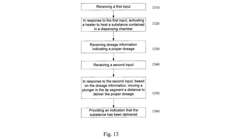
Figure 13 is a block diagram of a method of operating a drug delivery hand
piece according to an embodiment of the present invention. In 1310, a first
input
is received. Typically, this first input is generated via a switch or button
located
on the hand piece. For example, a surgeon may activate a switch to turn the
heater on. In response to this first input, in 1320, a heater is activated to
heat a
substance contained in a dispensing chamber. Typically, current is provided to
the heater and controlled by the controller.
In 1330, dosage information is received. This dosage information is
typically received by the controller so that the controller can control the
operation
of the hand piece to deliver the required dosage. The dosage information may
be
located in the tip segment itself (on a memory or RFID tag as previously
described). In such a case, the dosage information is transferred from the tip
segment to the limited reuse assembly.
In 1340, a second input is received. Typically, this second input is
generated via a switch or button located on the hand piece. For example, a
surgeon may press a button to begin the delivery of the substance. In response
to this second input and based on the dosage information, in 1350, a plunger
is
moved in the tip segment to deliver the proper dosage of the substance. The
second input starts the drug delivery process. The controller uses this second
input and the dosage information to control the operation of the motor and
attached plunger. The control operates the motor to move the plunger a
distance
that delivers the specified dosage. Optionally, the controller may also use
the
dosage information to control the rate at which the motor moves the plunger.
In 1360, an indication that the substance has been delivered is provided.
This indication can be in the form of an illuminated LED. Optionally, an
indication
that the substance has reached the proper temperature range can be provided by
CA 02664160 2009-03-20
WO 2008/108887 PCT/US2007/080305
illuminating an LED as well. Further, the controller may also ensure that the
substance has reached the proper temperature before the substance is
delivered.
In such a case, the controller does not allow the second input to commence the
delivery process until the substance has reached the proper temperature range.
Figure 14 is a block diagram of a method of operating a drug delivery hand
piece according to an embodiment of the present invention. In 1410, a
connection between a tip segment and a limited reuse assembly is recognized.
Typically, a medical professional attaches the tip segment to the limited
reuse
assembly by, for example, screwing the tip segment onto the limited reuse
assembly. This connection is recognized by an electrical or RF connection
between the tip segment and the limited reuse assembly. For example, when the
tip segment contains an RFID tag and the limited reuse assembly contains an
RFID reader, the connection is recognized by the limited reuse assembly when
the RFID reader in the limited reuse assembly reads information from the RFID
tag in the tip segment. In other embodiments, an electrical or data interface
connects the tip segment to the limited reuse assembly to allow information to
be
read from the tip segment by the controller in the limited reuse assembly.
In 1420, the type of tip segment is determined by the limited reuse
assembly. Typically, the controller receives information about the type of tip
segment. This information is typically stored in or on the tip segment itself.
When
the tip segment is connected to the limited reuse assembly, the controller
receives information about the type of tip segment. The controller can use the
information about the type of tip segment to select an algorithm to control
the tip
segment. In 1430, the limited reuse assembly also receives dosage information.
This dosage information is received by the controller in a similar fashion.
31
CA 02664160 2009-03-20
WO 2008/108887 PCT/US2007/080305
In 1440, a first input is received. Typically, this first input is generated
via
a switch or button located on the hand piece. For example, a surgeon may
activate a switch to turn the heater on. In response to this first input, in
1450, a
heater is activated to heat a drug contained in a dispensing chamber.
Typically,
current is provided to the heater and controlled by the controller.
After the drug has been heated to the desired temperature range, in 1460,
the dosage information is used to control the rate of movement and distance
the
plunger travels. In 1470, a second input is received. Typically, this second
input
is generated via a switch or button located on the hand piece. For example, a
surgeon may press a button to begin the delivery of the substance. The second
input is only accepted by the hand piece after the drug has reached the proper
temperature range. In this manner, the initiation of the drug delivery is only
enabled after the drug has reached the proper temperature range. This prevents
the administration of the drug when it is not in the proper temperature range.
As
noted above, delivering the drug only when it is in the proper temperature
range
may be necessary for efficacy.
In response to this second input and based on the dosage information, in
1480, the motor is activated to move the plunger the tip segment to deliver
the
proper dosage of the drug. The second input starts the drug delivery process.
The controller uses this second input and the dosage information to control
the
operation of the motor and attached plunger. The control operates the motor to
move the plunger a distance that delivers the specified dosage. Optionally,
the
controller may also use the dosage information to control the rate at which
the
motor moves the plunger. In 1490, the drug is delivered into the eye from the
tip
segment.
32
CA 02664160 2009-03-20
WO 2008/108887 PCT/US2007/080305
Optionally, an indication that the substance has been delivered can be
provided. This indication can be in the form of an illuminated LED. Further,
an
indication that the substance has reached the proper temperature range can be
provided by illuminating an LED as well.
Figures 15A & 15B are a block diagram of a method of operating a drug
delivery hand piece according to an embodiment of the present invention. In
1505 a data connection is recognized between the tip segment and the limited
reuse assembly. This data connection can be a wireless connection like an RFID
connection, or it can be a wired connection like a data interface. In 1510,
the
limited reuse assembly receives information about the type of tip segment
connected to it. In 1515, using the information about the type of tip segment,
the
limited reuse assembly selects a suitable control algorithm. The controller
may
select one of several control algorithms stored in memory.
In 1520, a first input is received. In response to the first input, in 1525,
the
heater is activated to heat the substance contained in the tip segment. In
1530,
the controller receives temperature information from the tip segment. In 1535,
the controller controls the operation of the heater using the temperature
information. In such a case, the controller is configured to regulate the
heater.
The controller may control the amount of current to the heater to control the
temperature of the substance.
In 1540, the controller receives dosage information. In 1545, the
controller, using the dosage information, determines a distance that the
plunger
in the tip segment must be moved to deliver the proper dosage. In 1550, a
first
indication that the temperature of the substance has reached the proper
temperature range is provided. In 1555, after this first indication is
provided, a
second input is received. In response to this second input, in 1560, the motor
is
33
CA 02664160 2009-03-20
WO 2008/108887 PCT/US2007/080305
activated to move the plunger the distance to deliver the proper dosage. In
1565,
a second indication that the substance has been delivered is provided.
From the above, it may be appreciated that the present invention provides
an improved system and methods for delivering precise volumes of a substance
into an eye. The present invention provides a single use, disposable delivery
device tip segment that is capable of delivering a precise dosage without
reflux.
The tip segment interfaces with a universal hand piece limited reuse assembly
capable of operating different types of tip segments. The substance that is to
be
delivered into the eye, typically a drug, is maintained in a temperature range
by
the temperature control features of the present invention. The present
invention
is illustrated herein by example, and various modifications may be made by a
person of ordinary skill in the art.
Other embodiments of the invention will be apparent to those skilled in the
art from consideration of the specification and practice of the invention
disclosed
herein. It is intended that the specification and examples be considered as
exemplary only, with a true scope and spirit of the invention being indicated
by
the following claims.
34