Note: Descriptions are shown in the official language in which they were submitted.
CA 02664179 2009-03-20
WO 2008/039347 PCT/US2007/020370
= TITLE OF THE INVENTION
Refuge Chamber and Method
=
FIELD OF THE INVENTION
[0001] = The present invention is related to a refuge
chamber that can easily be moved with a fork lift or front
end- loader. More
specifically, the present invention is
related to a refuge chamber that can easily be moved with a
fork lift or front end loader having a skid and a tent that
is disposed in the skid in an undeployed state which is
expandable to a deployed state and extends from the skid to
provide a protected atmosphere for the miners.
BACKGROUND OF THE INVENTION
[0002]
Existing refuge chambers are typically a steel
structure that is 6 foot high, 6 feet wide and can be from 14
to 20 feet in length, as shown in figure 1.. This makes it
difficult to move into a mine as well as move in a mine when
they are deployed.
[0003]
Typically, .coal mines advance at 50 to 75 feet per
day. Obviously, in tunnel boring and other types of mining
they tend to advance away from the surface opening and fresh
air sources. In order to ensure that the refuge chamber is
located close to the mining areas and typically these refuge
chambers need to be within 500-1000 feet of the working area.
This means they have to be moved on a regular basis.
CA 02664179 2009-03-20
WO 2008/039347 PCT/US2007/020370
=
[ 0004] The refuge chamber of the present invention can be
* moved easily due to its smaller size and height. As the fresh
Air Bay tent is inside the skid, it remains protected until
it needs to be deployed.
[0005] The refuge chamber then can be used to provide .
breathable air in the event of an emergency as typically fans
and ventilation structures can be damaged or are turned off
to remove potential sparks and air from any fire.
[0006] Rooms are also built into the mines and act as
refuge chambers. These have limited application and new
rooms have to be built as the mines advance. The refuge
chamber can simply be moved along with the mining equipment.
BRIEF SUMMARY OF THE INVENTION
[0007] The present invention pertains to a refuge chamber
for miners in a mine. The chamber comprises a skid. The
chamber comprises a tent that is disposed in the skid in an
undeployed state which is expandable to a deployed state and
extends from the skid to provide a protected atmosphere for
the miners.
[0008] The present invention pertains to a method for
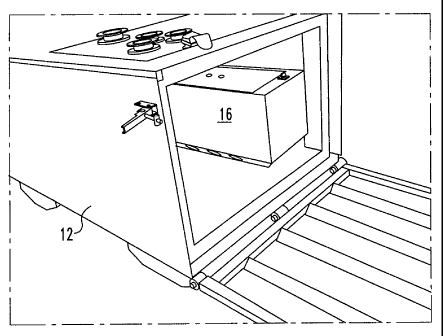
providing a refuge chamber for miners in a mine. The method
comprises the steps of opening a skid made of metal. There
. is the step of expanding a tent that is disposed in the skid
in an undeployed state to a deployed state that extends from .
. the skid to provide a protected atmosphere for the miners.
-2-
CA 02664179 2009-03-20
WO 2008/039347 PCT/US2007/020370
=
BRIEF DESCRIPTION OF THE SEVERAL VIEWS OF THE DRAWING
[0009] In the accompanying drawings, the preferred
embodiment of the invention and preferred methods of .
practicing the invention are illustrated in which:
[0010] Figure 1 shows a prior art refuge chamber.
[0011] Figure 2 shows the skid during construction showing
the'front door and scrubber positioned in the skid of the
refuge chamber of the present invention.
[0012] Figure 3 is an internal view of the skid showing
drawers and the front of the compressed air and oxygen
. bottles..
=[0013] Figure 4 shows a rear inspection door to access
drawers and supplies.
=
[0014] Figure 5 shows the metal skid as it is transported
and stored.
[0015] Figure 6 shows the door of the skid being opened
and the position of the tent prior to being inflated or
erected.
=
= [0016] Figure 7 shows the tent being deployed.
= [0017] Figure 8 shows the rear inspection door of the
skid.
-3-
=
CA 02664179 2009-03-20
WO 2008/039347 PCT/US2007/020370
[0018] Figure 9 shows the.self-supporting tent attached to
the skid. =
[0019] Figure 10 shows the inflatable structure that is
inside the tent.
[0020] Figure 11 shows the tent.
[0021] Figure 12 shows the inside of the tent.
[0022] Figure 13 is a perspective view of the skid.
[0023] Figure 14 is a view of the top of the skid.
[0024] Figure 15 is a view of the bottom of the skid.
[0025] Figure 16 shows the end door found on both sides of
the skid.'
[0026] Figure 17 shows the bottle support.
[0027] Figure 18 shows a view of the bottle bay and
drawers.
[0028] Figure 19a is an end view of a preferred embodiment
of the skid.
[0029] Figure 19b is an end view of a preferred embodiment
of the skid.
-4-
CA 02664179 2009-03-20
WO 2008/039347 PCT/US2007/020370
[0030] Figure 19c is an internal view of the drawer system
and. the bottles.
[0031] Figure 19d is a side view of the skid with the
doors closed.
[0032] Figure 19e is in and view of the drawer system and
the bottles,
[0033] Figure 19f is a side view of the portions of the
end of the skid with the hinges.
[0034] Figure 19g is a side view of the skid with the
= doors open.
DETAILED DESCRIPTION OF THE INVENTION
[0035] Referring now to the drawings wherein like
reference numerals refer to similar or identical parts
throughout the several views, and more specifically to
= figures 5-8 thereof, there is shown a refuge chamber 10 for
miners in a mine. The chamber 10 comprises a skid 12. The
chamber 10 comprises a tent 14 that is disposed in the skid .
12 in an undeployed state which is expandable to a deployed
state and extends from the skid 12 to provide a protected
= atmosphere for the miners.
[0036] Preferably, the skid 12 has a scrubber 16. The
skid 12 preferably has a cooling system 18. Preferably, no
external power is required to operate the scrubber 16 or
cooling system 18. The skid 12 preferably has an inspection
= door 20.
-5-
=
CA 02664179 2009-03-20
WO 2008/039347 PCT/US2007/020370
=
[0037]
Preferably, the skid 12 has a drawer system 22 that
is accessed from the tent 14, as shown in figures 4 and 5.
The tent 14 preferably includes an expandable support'
structure 24, as shown in figure 10, and a seal 26 which
seals the tent 14 to the skid 12 in a deployed state.
Preferably, the tent 14 has an airlock 28. The
support
structure 24 is preferably expandable from an undeployed
state to a deployed state. Preferably, the support structure
24 is inflatable.
=
[0038] The
present invention pertains to a method for
providing a refuge chamber 10 for miners in a mine. The
method comprises the steps of opening a skid 12 made of
metal. There is the step of expanding a tent 14 that is
disposed in the skid 12 in an undeployed state to a deployed
state that extends from the skid 12 to provide a protected
atmosphere for the miners.
[0039] The
skid 12 can be operated without any power or
power connection - this means that if the power is
disconnected, the structure can still be deployed and used.
The fans in the scrubber 16 are run with compressed air and
the breathable air is supplied via oxygen bottles 30 that are
. located in the skid 12. The cooling system 18 can also be
powerless, as more fully described below.
[0040] By being made of metal and preferably steel, it can
withstand explosions.
[0041] The compressed air is already connected to the
scrubber 16 motor. All the miners need to do is turn on the
smith/valve to activate the system. The skid 12 contains a
-6-
CA 02664179 2009-03-20
WO 2008/039347 PCT/US2007/020370
bank of compressed air bottles 30 - they are used to run the
scrubber 16 motor as well as fill the tent 14 and purge the
tent 14 and air lock if required. Medical grade oxygen is
also in bottles 30 - normally four of them to provide the
breathable air (replaces the air consumed) that is metered
into the skid 12/tent 14 using a ball valve medical flow
meter that is set depending on the number of people in the
tent 14. The rate is predetermined at 30 liters per person
per hour. The instructions in the skid 12 tell the occupants
how to set the flow rate.
[0042] Inspection door 20 provides easy inspection and
=
allows supplies to be changed as necessary.
[0043] The skid 12 contains a drawer system 22 that allows
all the supplies like soda lime (for the Scrubbing, water,
food, first aid kit to be stored safely). This drawer system
22 has the unique feature that it can be accessed form the
.inside of the tent 14. It can also be accessed from the
inspection door 20 for routine maintenance.
[0044] Cooling is normally required in a refuge chamber 10
due the heat generated by the occupants, the scrubbing
operation and in some cases by the temperature underground.
= Normally, an air conditioner is fitted into a refuge chamber
to provide cooling. This requires an electrical connection
or a battery backup system. These can be unsafe in a coal
mine due to potentially explosive gases and typically require
special approvals and safety features. Presently, no air
conditioners are approved for use in this environment. Two
alternative cooling systems 18 are described herein.
-7-
CA 02664179 2009-03-20
WO 2008/039347 PCT/US2007/020370
[0045] The
first system used a refrigeration system in the
skid 12 that is loaded with chemical ice pack. These stored
ice blocks can then be used to cool the chamber 10 in the
event of an emergency. The
power will be disconnected,
however the refrigeration unit stores and keeps the frozen
pack until they are needed.
[0046]
Another alternative is a chemical cooling pack that
is stored in the skid 12 and used as required. - this has no
power connection.
[0047] The
cooling requirements have been calculated based
on the mine temperature, occupancy rate and the expected time
of the tent 14 occupancy and can match the requirement to the
amount of cool storage/chemical cooling systems 18 required.
[0048]
Another unique feature of the skid 12 is that it is
tight and so the tent 14 and the skid 12 become an integral
unit when the tent 14 is opened. The tent 14 is connected to
the tent 14 via a bellows construction and gasket arrangement
=
and is fixed to the skid 12.
[0049] The
system has two distinct types of tent 14
attachments.
[0050] The
first type is a tent 14 that is erected: using
compressed air that is used to blow up structural elements.
The tent 14 is attached to these elements and erects on its
own.
=
=
[0051] The
other tent 14 is a manually erectable tent 14
that is self supporting and is drawn out of the skid 12
-8-
CA 02664179 2009-03-20
WO 2008/039347 PCT/US2007/020370
manually. It is designed
with a structure that is self
supporting and required no erection, apart from being pulled
out from the skid 12. It expands in an accordion fashion
from its undeployed state and is formed from plastic or metal
strips connected together similar to an expandable gate. One
of the further advantages of these tents 14 is that they can
be made of any mine height - and that can be as low as 30
inches high. Occupants would crawl into the tent 14 in the
case of a low mine height and then activate the controls in
the skid '12 in the normal fashion.
= [0052] The tent 14 has an air lock compartment so that the
tent 14 can be entered without contamination of the entire
fresh air bay. At the entrance to the tent 14, there is a
small area with an inner flap that is zippered to the
external wall which defines the air lock. A purge valve 32
connected to the compressed air valve allows the air in the
air lock compartment to be purged. When the air lock has
been purged and replaced with air from the compressed air
bottle, the zipper can be opened to allow access to the main
part of the tent 14. Tubing 34 extends from the skid 12 to
which bottles 30 are connected to the air lock.
= [0053] Another feature and advantage of the tent 14 is
that the one way valves 36 are located on the top of the tent
14 so that the hottest air is escaping from the tent 14
helping to moderate the temperature. As air is constantly
being released from the oxygen cylinders, it is necessary to
have air relief valves to stop an over pressurization of the
tent 14 structure.
-9-
CA 02664179 2009-03-20
WO 2008/039347 PCT/US2007/020370
=
=
[0054]
Figure 2 shows the skid 12 during construction
showing the front door and scrubber 16 positioned in the skid
12. The scrubber 16 is fitted with an air motor. The tent
14 is attached to this side with a.sealed diaphragm. The
inside of the skid 12 can be accessed from the inside of the
tent 14.
[0055]
Figure 3 is an internal view of the skid 12 showing
. drawers with all provisions and the front of the compressed
air .and oxygen bottles 30. Figure 4 shows a rear inspection
door 20 to access drawers and supplies.
[0056]
Diagrammatically, the unit would work as follows:
[0057]
Figure 5 shows the metal skid 12 as it is
transported and stored.
[0058]
Figure 6 shows the door of the skid 12 being opened
and the position of the tent 14 prior to being inflated or
erected.
=
[0059] Figure 7 shows the tent 14 being deployed.
[0060]
Figure 8 shows the rear inspection door 20 of the
skid 12.
[0061]
Figure 9 shows the self-supporting tent 14 attached
to a skid 12.. The air lock is in front.
[0062]
Figure 10 shows the inflatable structure that is
inside the tent 14. =
-10-
CA 02664179 2009-03-20
WO 2008/039347 PCT/US2007/020370
[0063] Figure 11 shows the tent 14.
=
[0064] Figure 12 shows the inside of the tent 14.
[0065] The refuge chamber 10 has a steel skid 12 mounted
box that.contains all items required to allow trapped miners
to survive in .irrespirable air for a period of time of at
least four days or longer if equipped for that purpose..
[0066] The steel box is explosion proof (up to 15PSI) can
be moved and placed in a suitable area in the mine.
[0067] The steel box contains the following =unique
features:
= Drawer systems 22 to hold supplies
= Water
= Food
= Spare lights
= = Batteries
= Air monitoring devices
= = First Aid kit
= Other necessary supplies
= Scrubber 16 that can be air powered or battery
operated to scrub CO2
= Oxygen and Compressed air bottles 30
= Control systems to manage and control the flow
of oxygen and compressed air
= Tent 14 system can be:
= Inflatable with compressed air
= Or manually erectable
-11-
CA 02664179 2009-03-20
WO 2008/039347 PCT/US2007/020370
[0068] The steel box has an inspection door 20 so that .
items in the box can be changed out periodically or inspected
without deploying the tent 14.
[0069] The steel box has a door that opens out and allows
the tent 14 to be erected.
[0070] The steel box is air tight.
[0071] The interior of the tent 14 is linked and the
inside of the box can be accessed from the tent 14.
[0072] The size of the steel box is approximately 10 feet
long 50 inches wide and 36 inches tall and allows for easy
movement inside the mine and into the mine.
=
=
[0073] The unique features consist of the following
features:
= The entire concept of having a portable life
support system.
= The fact that all items are sized to fit into
=
the steel box making the system totally
portable.
= The steel box linked into the tent 14 and
having all the controls and equipment in the
box.
= The explosion proof design of the box.
= The manually self standing/supporting tent 14.
= The fact that the whole system can be operated
without any external power source.
-12-
CA 02664179 2012-04-11
=
[0074] Figure 13 is a perspective view of the constructed
skid made of metal. Figure 14 is a view of the top of the
skid. In the panels that make up the walls of the skid are
angles 40 that are stitch welded with toes against the panel.
[0075] Figure 15 is a view of the bottom of the skid. The
bottle support 38 is positioned in the bottom of the skid.
[0076] , Figure 16 shows the end door found on both sides of
. = the skid. Figure 17 shows the bottle support 38. Figure 18
shows a view of the bottle bay and drawers.
. [0077] Figure 19a is an end view of. a preferred embodiment '
of the skid. Figure 19b is an end view of a preferred
embodiment of the skid. Figure 1.9c is an internal view of
the drawer system and the bottles 30. Figure 19d is a side
view of the skid with the doors closed. Figure 19e is an end
view of the drawer system and the bottles 30. Figure 19f is
a side view of the portions of the end of the skid with the
hinges. Figure 19g is a side view of the skid with the doors
open.
-13-