Note: Descriptions are shown in the official language in which they were submitted.
CA 02664282 2014-01-31
METAL SEAL FOR WELLHEADS
BACKGROUND OF THE INVENTION
1. Field of the Invention
The invention relates to a metal seal for use in wellheads for use in oilfield
wells.
2. Description of the Related Art
Various types of metal seals have been used for many years in wellheads.
1
CA 02664282 2014-01-31
SUMMARY OF THE INVENTION
In accordance with the illustrative embodiments hereinafter described, the
present metal
seal may provide a metal-to-metal seal between a casing head and a tubing
head, the casing head
and tubing head each having a tapered wall surface adapted for engagement with
the seal. The
seal may include an annular seal member having an upper and a lower end and an
inner wall
surface and an outer wall surface, an upper tapered sealing flank disposed on
the outer wall
surface of the seal member disposed adjacent the upper end of the annular seal
member, a lower
tapered sealing flank disposed on the outer wall surface of the seal member
disposed adjacent the
lower end of the annular seal member. The upper and lower tapered sealing
flanks may have a
first diameter before engagement with the tapered wall surfaces of the casing
head and the tubing
head, and the upper and lower tapered sealing flanks may have a second
diameter after
engagement with the tapered wall surfaces of the casing head and the tubing
head. The second
diameter may be smaller than the first diameter. After the seal member is
removed from
engagement with the tapered wall surfaces of the tubing head and the casing
head, the upper and
lower tapered sealing flanks may have a third diameter, and the third diameter
may be
substantially the same as the first diameter.
BRIEF DESCRIPTION OF THE DRAWINGS
The present metal seal for a wellhead may be understood by reference to the
following
description taken in conjunction with the accompanying Drawings, in which:
FIG. 1 is a partial cross-sectional view of an illustrative view of a wellhead
provided with
an illustrative embodiment of the present metal seal; and
FIG. 2 is an exploded cross-sectional view of a portion of the wellhead of
FIG. 1 within
the dotted line circle denoted FIG. 2 in FIG. 1.
2
CA 02664282 2014-01-31
While certain embodiments of the present metal seal will be described in
connection with
the preferred illustrative embodiment shown herein, it will be understood that
it is not intended to
limit the invention to that embodiment.
DETAILED DESCRIPTION OF THE SPECIFIC EMBODIMENTS
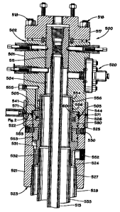
In FIGS. 1 and 2, one illustrative embodiment of a wellhead, or wellhead
system, 500
with which the present metal seal may be used is illustrated. Wellhead system
500 is seen to
generally include a tubing head 501, a tubing hanger 511, a casing head 521, a
casing hanger 531,
and a connector 541, which releasably connects the tubing head 501 to casing
head 521.
Tubing head 501 has a generally annular-shaped cross-sectional configuration,
and has an
upper end 502, a lower end 503, and a bore 504 extending from the upper end
502 to the lower
end 503 of the tubing head 501. A first set of threads 505 is disposed upon an
outer surface 506
of tubing head 501, the first set of threads 505 being preferably disposed
adjacent the lower end
503 of tubing head 501, as shown in FIGS. 1 and 2. As will be hereinafter
described, the first set
of threads 505 is preferably a left-hand set of threads.
Tubing hanger 511 may be of any design compatible with tubing head 501, and is
disposed in the bore 504 of the tubing head 501. Tubing hanger may have a
length of production
tubing 513 suspended from it. Tubing head 501 may have a tubing adapter 517
disposed above
the upper end 502 of tubing head 501, and the tubing adapter 517 may be
secured to tubing head
501 as by a plurality of nuts and bolts 518. At least one, and preferably two,
studded side outlets
520 may be provided and sealingly secured to tubing head 501, whereby
conventional valves,
such as gate valves (not shown) may be secured. Studded side outlet(s) 520 are
typically in fluid
communication with the bore 504 of tubing head 501.
With reference to FIGS. 1 and 2, casing head 521 is of a generally annular
shaped
cross-sectional configuration and has an upper end 522, a lower end 523, and a
bore 524
3
CA 02664282 2014-01-31
extending from the upper end 522 to the lower end 523 of the casing head 521.
Any suitable type
of casing head 521 could be utilized, such as the illustrated fluted casing
head 521, used in
combination with a conventional pack off member 590. A second set of threads
525 are disposed
on an outer surface 526 of the casing head 521, and preferably the second set
of threads 525 are
disposed adjacent the upper end 522 of the casing head 521. Preferably, the
second set of threads
525 are a right-hand set of threads. Casing hanger 531 is disposed in the bore
524 of casing head
521. Casing hanger 531 is provided with a plurality of threads 532, which
threadedly engage
with the threads on the upper end of a length of production casing 533. Casing
head 521 may
also include a set of threads 527 which threadedly engage with a set of
threads on the upper end
of a length of an outer, or surface, casing 528. Additionally, casing head 521
may also include
one or more seal test ports 530. Casing head 521 may also include, if desired,
a threaded side
outlet 552 and a plurality of conventional seals 553. The seal test ports 530
may be used to test
the seal between seals 553 in a conventional manner.
Still with reference to FIGS. 1 and 2, the lower end 503 of tubing head 501
may be
provided with an internal female recess, or bore, 554, which may receive the
upper end of the
casing hanger 531 in a sealed relationship as by the conventional seals 556.
Tubing head 501
may also include a flange test port 555 which may be used in a conventional
manner to test the
sealed relationship between the lower end 503 of tubing head 501 with the
upper end 522 of
casing head 521. hi this regard, as better seen in FIG. 2, a mating, or
abutting, connection 560 is
provided between the lower end 503 of tubing head 501 and the upper end 522 of
casing head
521, wherein the lower end 503 of tubing head 501 abuts the upper end 522 of
casing head 521
when the tubing head 501 and casing head 521 are in their sealed relationship
as shown in FIG. 2.
Still with reference to FIGS. 1 and 2, connector 541 is shown to include a
member 542
having an interior surface 543 which threadedly engages at least a portion of
the first and second
sets of threads 505, 525, on the tubing head 501 and the casing head 521. The
interior surface
543 of connector member, or member, 542, has a generally circular cross-
sectional configuration
to threadedly mate with the threaded exterior outer wall surfaces of the
tubing head 501 and
4
CA 02664282 2014-01-31
casing head 521. Preferably connector member, or member, 542 is annular
shaped, whereby its
outer wall surface 544 also has a generally circular cross-sectional
configuration, however, it
should be noted that the outer cross-sectional configuration of the member 542
could be circular,
square, hexagonal, etc. as desired.
The interior surface 543 of member 542 is provided with two sets of threads,
545, 546.
One of the sets of threads is a set of left-hand threads, and the other set of
threads is a set of
right-hand threads. Preferably the upper set of threads 545 is a set of left-
hand threads which
engage the first set of threads 505 on the tubing head 501, which are also
preferably a set of
left-hand threads. Similarly, the lower set of threads 546 is a set of right-
hand threads which
engage the second set of threads 525 on the casing head 521, which are also
preferably a set of
right-hand threads. Thus, the set of threads 505 on the tubing head 501 may be
threadedly
received within connector 541 and threadedly engaged with the upper set of
threads 545 of
connector 541, and the second set of threads 525 of the casing head 521 may be
received within
connector 541 and threadedly engaged with the lower set of threads 546 of
connector 541. It
should be readily apparent, that if desired, the first set of threads 505
could be a set of right-hand
threads, the upper set of threads 545 could be a set of right-hand threads,
the second set of
threads 525 of casing head 521 could be a left-hand set of threads, and the
lower set of threads
546 of connector 541 could also be a left-hand set of threads.
If the sets of threads 505, 545 are sets of let-hand threads, and the sets of
threads 525 and
546 are right-hand sets of threads, upon the tubing head 501 and the casing
head 521 being
initially brought into threaded engagement with connector 541, upon rotation
of connector 541 in
a right-hand fashion, or in a clockwise direction when viewed from the top of
wellhead system
500, the rotation of connector 541, or connector member 542, will cause
relative movement of
connector 541 with respect to both the tubing head 501 and the casing head
521; and the tubing
head 501 and the casing head 521 will be drawn toward each other until they
are in the sealed
relationship illustrated in FIG. 2. Similarly, if the first set of threads 505
and the upper set of
threads 545 are right-hand sets of threads and the second set of threads 525
and the lower set of
CA 02664282 2014-01-31
threads 546 are each left-hand sets of threads, upon rotation of connector 541
in a left-hand
fashion, or in a counterclockwise direction when viewed from the top of
wellhead system 500,
again the tubing head 501 and casing head 525 will be drawn together into the
sealed relationship
illustrated in FIG. 2. In either embodiment, rotation of connector 541 may be
provided in any
suitable manner, such as by handles (not shown) which may be threaded into
threaded openings
571 in connector.
With reference to FIG. 2, a seal 600 may be disposed between tubing head 501
and casing
head 521. Seal 600 is a tapered, pressure energized seal, in that pressure
forces from within
tubing head 501 and casing head 521 acting upon seal 600 will enhance the
sealing effect of seal
600. Seal 600 is generally an annular shaped member, or seal member, 601,
having upper and
lower tapered sealing flanks, seal lips, or tapered seal surfaces 602, 603,
disposed on the outer
wall surface 604 of seal member 601. The angle 610 of the taper for sealing
flanks 602, 603 is
generally within the range of 50- 70, and may be characterized as a relatively
shallow taper. An
outer annular rib, or ridge member, 615 may be formed, or disposed, on the
outer wall surface
604 of seal member 601, as seen in FIG. 2. Preferably, the cross-sectional
configuration of
annular rib is rectangular; however, other cross-sectional configurations,
such as square, or
trapezoidal, could be utilized.
After seal 600 is installed in casing head 521, as connector 541 is rotated,
as previously
described, to draw tubing head 501 and casing head 521 together into the
sealed relationship
shown in FIG. 2, sealing flanks 602 and 603 engage tapered wall surfaces 620
and 621, formed
on the lower end of tubing head 501 and the upper end of casing head 521,
respectively. The
angle 630 of the taper of tapered wall surfaces 620 and 621, may be the same
as angle 610, but
preferably is less, or shallower, than the angle 610, and is generally within
the range of 30- 60, so
that an interference fit is provided between the sealing flanks 602, 603 and
the tapered wall
surfaces 620, 621. Thus, as tapered sealing flanks 602, 603 and tapered wall
surfaces 620, 621
are drawn together with this interference fit, a metal-to-metal seal is
provided between tubing
head 501 and casing head 521. As the taper of tapered sealing flanks 602, 603
and tapered wall
6
CA 02664282 2014-01-31
surfaces 620, 621 are relatively shallow, the makeup torque required to
energize seal 600 is
minimized. Seal 600 is reusable, as the force applied to seal 600 is less than
the elastic limit of
the material from which seal 600 is manufactured. Thus, upon a metal-to-metal
seal being
created by seal 600 between tubing head 501 and casing head 521, seal 600 is
not permanently
distorted by the movement of tubing head 501 and casing head 521, as
previously described.
Generally, the seal member 601 at its upper and lower ends, defined by the
tapered
sealing flanks 602, 603, has a first, or undeflected, diameter before being
installed in casing head
521. After casing head 521 and tubing head 501 are placed in their sealed
relationship as
previously described and as shown in FIG. 2, the tapered wall surfaces 620,
621 of the tubing
head 501 and the casing head 521 act upon the upper and lower tapered sealing
flanks 602, 603
to cause sealing flanks 602, 603 to be deflected inwardly, as the metal-to-
metal seal is being
made, whereby the seal member 601 at its upper and lower ends has a second, or
deflected or
distorted, diameter which is less than the first diameter. After the
disconnection, or disassembly
of tubing head 501 and casing head 521, the seal member, or its upper and
lower tapered sealing
flanks, springs or moves outwardly to a third diameter which is substantially
the same as, if not
the same, as the first undeflected, undistorted diameter, whereby seal 600 may
be reused.
Still with reference to FIG. 2, the upper end 522 of casing 521 may be
provided with an
annular groove, or rabbit groove 616, which receives rib, or ridge member,
615. Each of the
sealing flanks, or seal lips, 602, 603, may be provided with an annular relief
groove 617. An
annular relief groove 618 may be formed in the interior wall surface 619 of
seal member 601.
The cross-sectional configuration of the relief grooves 617 is preferably
rectangular; however,
other cross-sectional configurations could be utilized, such as square, semi-
circular, or
trapezoidal. Similarly, the cross-sectional configuration of the relief groove
618 is preferably
rectangular; however, other cross-sectional configurations, such as those
previously described
could be utilized.
The relief grooves, or force relief grooves, 617 and 618, provide for
controlled deflection
7
CA 02664282 2014-01-31
of sealing flanks 602, 603, as they become engaged in the previously described
interference fit
with the tapered wall surfaces 620 and 621 on the lower end of tubing head 501
and the upper
end of casing head 521. The relief grooves 617, 618, also assist in insuring
that sealing flanks
602, 603 are not deflected upon make-up, beyond the elastic limit of the
material forming seal
member 601, so that sealing flanks 602, 603 are not permanently deflected, or
distorted, upon
make-up, but may spring back into substantially their original configuration
upon disassembly of
tubing head 501 and casing head 521, as by rotation of connector 541, as
previously described.
Preferably, as shown in FIG. 2, pressure relief grooves 617 are disposed
substantially
intermediate the upper and lower ends of each sealing flank 602, 603; however,
relief grooves
617 could be disposed upwardly or downwardly from their locations illustrated
in FIG. 2.
Similarly, relief groove 618 on the interior surface 619 of seal member 601 is
preferably disposed
intermediate the top and bottom of seal member 601, and opposite from annular
rib, or ridge
member, 615. It should be noted that the size of relief grooves 617, 618 may
be varied.
Additionally, more than one groove 618 could be provided, such as a plurality
of smaller grooves
disposed opposite ridge member 615. Further, additional relief grooves 617
could also be
provided if desired. Additionally, if desired, relief grooves 617 and 618 may
not be used, or
alternatively, relief grooves 617 could be deleted and relief grooves 618
could be provided, or
relief grooves 617 could be utilized without relief groove 618.
It should be noted that seal 600 may be formed of any suitable material having
the
requisite strength, flexibility, and sealing characteristics to function in
the manner previously
described. Suitable materials from which to make the foregoing described seals
include, but are
not limited to, stainless steel and Inconel , which is a family of nickel-
based superalloys made
by Special Metals Corporation. It should be further noted that although the
foregoing seals are
illustrated for use in connection with wellhead 500, and to provide sealing
between tubing heads
and casing heads, the present seals could be utilized to effect and provide
seals between other
wellhead components, such as between casing heads and extension spools, and
between landing
and installation tools, as well as other wellhead components. In this regard,
the use of the terms
8
CA 02664282 2014-01-31
"tubing head" and "casing head" in the appended claims is intended to
encompass these other
types of wellhead components. Coatings of different types may be applied to
the seal 600 for
corrosion protection.
All of the previously described components may be manufactured of any suitable
materials having the requisite strength characteristics to function in the
manner described for the
use of such components. Any type of thread profile may be utilized for the
previously described
sets of threads provided the thread profile permits the sets of threads to be
engaged and operate in
the manner previously described.
Specific embodiments of the present seal have been described and illustrated.
It will be
understood to those skilled in the art that changes and modifications may be
made.
9